

Service Manual
Page 4
... Image troubleshooting 113 ........1. Data cannot be performed via the serial interface. 111 ........9. Cyclic error 117 Black belts or stripes in the vertical direction 116 ........5. I /F time-out 108 between the printer and the operator 109 panel (ERROR 80) . ........7. Dark background density 115 ........4. Table of Contents Page 4.2 Adjustment When Replacing A Part 81 ....4.2.1 Setting of LED head drive time 82 ....4.2.2 Resetting the fuser counter 83 ....4.2.3 Destination setting 84 5 Periodic Maintenance 5.1 Periodic Parts Replacement 85 5.2 Cleaning...
... Image troubleshooting 113 ........1. Data cannot be performed via the serial interface. 111 ........9. Cyclic error 117 Black belts or stripes in the vertical direction 116 ........5. I /F time-out 108 between the printer and the operator 109 panel (ERROR 80) . ........7. Dark background density 115 ........4. Table of Contents Page 4.2 Adjustment When Replacing A Part 81 ....4.2.1 Setting of LED head drive time 82 ....4.2.2 Resetting the fuser counter 83 ....4.2.3 Destination setting 84 5 Periodic Maintenance 5.1 Periodic Parts Replacement 85 5.2 Cleaning...

Service Manual
Page 12
...) Image drum cartridge 30,000 (at continuous printing) 20,000 (3 page/job) 15,000 (1 page/job) Service Guide OL1200 Chapter 1 Configuration Page: 5 1.4 Specification (1) Type Desk top (2) External dimensions Height 10.6 (270 mm) (excludes protruding Width 14.4 (366 mm) Portion) Depth 16.9 (430 mm) (3) Weight 15.2 kg (33.5 lbs) (4) Development method Dry electrophotography Exposure method LED stationary head (5) Paper used - Standard sizes Letter Legal Executive Envelope A4 A5 B5 A6 - Application paper (manual...
...) Image drum cartridge 30,000 (at continuous printing) 20,000 (3 page/job) 15,000 (1 page/job) Service Guide OL1200 Chapter 1 Configuration Page: 5 1.4 Specification (1) Type Desk top (2) External dimensions Height 10.6 (270 mm) (excludes protruding Width 14.4 (366 mm) Portion) Depth 16.9 (430 mm) (3) Weight 15.2 kg (33.5 lbs) (4) Development method Dry electrophotography Exposure method LED stationary head (5) Paper used - Standard sizes Letter Legal Executive Envelope A4 A5 B5 A6 - Application paper (manual...

Service Manual
Page 18
Memory capacity setting Memory area Use MENU Expansion RAM EPROM/ OTP or masked ROM is used as resident memory to OST LSI Control of Centronics parallel interface Control of RS-232C serial interface Generation of various control timing Monitoring of paper running and paper size Control of operator panel, EEPROM, and options Inputting/outputting of sensor, signal and motor signal Control of OKI HSP interface (2) Program/font ROM The program/font ROM...
Memory capacity setting Memory area Use MENU Expansion RAM EPROM/ OTP or masked ROM is used as resident memory to OST LSI Control of Centronics parallel interface Control of RS-232C serial interface Generation of various control timing Monitoring of paper running and paper size Control of operator panel, EEPROM, and options Inputting/outputting of sensor, signal and motor signal Control of OKI HSP interface (2) Program/font ROM The program/font ROM...

Service Manual
Page 19
... printer. - In addition, it transfers serially bit image data for each dot line to the LED head. (7) Host interface This printer has the following interfaces to the host. Menu data - Unidirectional communications from the printer to the host. - Various counter data (page counter, drum counter, fuser counter, etc.) - OKI HSP interface (Option) The single effective interface or the automatic interface select mode can be selected using the menu. Stores soft fonts and macro data...
... printer. - In addition, it transfers serially bit image data for each dot line to the LED head. (7) Host interface This printer has the following interfaces to the host. Menu data - Unidirectional communications from the printer to the host. - Various counter data (page counter, drum counter, fuser counter, etc.) - OKI HSP interface (Option) The single effective interface or the automatic interface select mode can be selected using the menu. Stores soft fonts and macro data...

Service Manual
Page 20
... supplied by third venders) such as the LAN connection expansion board. When the power is turned on the Control board without modifying the program at the printer side. RBST X-ON (For the electrical/physical characteristics of two nibbles using eight data signal leads under the semi-duplex control by Okidata) - The conceptual diagram of the OKI HSP interface is shown in Fig. 2-2. (For...
... supplied by third venders) such as the LAN connection expansion board. When the power is turned on the Control board without modifying the program at the printer side. RBST X-ON (For the electrical/physical characteristics of two nibbles using eight data signal leads under the semi-duplex control by Okidata) - The conceptual diagram of the OKI HSP interface is shown in Fig. 2-2. (For...

Service Manual
Page 48
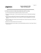
PARTS REPLACEMENT The section explains the procedures for the installation. Copyright 1997, Okidata, Division of parts, assemblies, and units in the field. Only the removal procedures are explained here. Reverse the procedure for replacement of OKI America, Inc. See the OKIDATA Business Partner Exchange (BPX) for any updates to this material. (http://bpx.okidata.com) All rights reserved. Service Guide OL1200 Chapter 3 Parts Replacement Page: 28 3.
PARTS REPLACEMENT The section explains the procedures for the installation. Copyright 1997, Okidata, Division of parts, assemblies, and units in the field. Only the removal procedures are explained here. Reverse the procedure for replacement of OKI America, Inc. See the OKIDATA Business Partner Exchange (BPX) for any updates to this material. (http://bpx.okidata.com) All rights reserved. Service Guide OL1200 Chapter 3 Parts Replacement Page: 28 3.
Service Manual
Page 56
... the Assy 8 in black plastic bag shipped w/printer. (3) Open the face-up stacker Assy, and I /F cover Assy 7. (6) Remove two screws 9 and four claws A. (Use a small flat blade screw driver to disengage 8A from the outlet. (2) Remove the interface cable 1. Remove drum/toner Assy 2A and store in the middle to "pop" claws.) Remove the rear cover 10. Service Guide OL1200 Chapter 3 Parts Replacement Page: 36 3.3.1 Rear cover, side cover (L) Assy, face-up stacker...
... the Assy 8 in black plastic bag shipped w/printer. (3) Open the face-up stacker Assy, and I /F cover Assy 7. (6) Remove two screws 9 and four claws A. (Use a small flat blade screw driver to disengage 8A from the outlet. (2) Remove the interface cable 1. Remove drum/toner Assy 2A and store in the middle to "pop" claws.) Remove the rear cover 10. Service Guide OL1200 Chapter 3 Parts Replacement Page: 36 3.3.1 Rear cover, side cover (L) Assy, face-up stacker...

Service Manual
Page 112
User maintenance mode To enter the user maintenance mode, turn on the POWER switch while pressing the FORM FEED key and ENTER key. Hex dump - X adjust - Rolling ASCII continuous printing - Head drive time setting - Drum count display - Setting of second tray feeder download table - Selection of second tray paper feed length - Menu reset - Page count printing enable/disable - EEPROM reset - Setting of OKI America, Inc. Engine reset Copyright 1997, Okidata, Division of front feeder paper feed length - See the OKIDATA Business Partner Exchange (BPX) for any updates to the ...
User maintenance mode To enter the user maintenance mode, turn on the POWER switch while pressing the FORM FEED key and ENTER key. Hex dump - X adjust - Rolling ASCII continuous printing - Head drive time setting - Drum count display - Setting of second tray feeder download table - Selection of second tray paper feed length - Menu reset - Page count printing enable/disable - EEPROM reset - Setting of OKI America, Inc. Engine reset Copyright 1997, Okidata, Division of front feeder paper feed length - See the OKIDATA Business Partner Exchange (BPX) for any updates to the ...

Service Manual
Page 113
... data when the user replaces the image drum unit. - This function is less than one page, printing can be activated manually be pressing the Form Feed key after selecting the OFF LINE. (Automatic activation of resetting. (4) Operator panel menu disable - All settings for all executable emulations including options are reset to adjust the printing start position within the range of ±2 mm in 0.25 mm steps in the X direction. (6) Y ADJUST - Service Guide OL1200 Chapter 4 Adjustment Page: 74 4.1.1 User maintenance mode...
... data when the user replaces the image drum unit. - This function is less than one page, printing can be activated manually be pressing the Form Feed key after selecting the OFF LINE. (Automatic activation of resetting. (4) Operator panel menu disable - All settings for all executable emulations including options are reset to adjust the printing start position within the range of ±2 mm in 0.25 mm steps in the X direction. (6) Y ADJUST - Service Guide OL1200 Chapter 4 Adjustment Page: 74 4.1.1 User maintenance mode...

Service Manual
Page 115
... first category after updating the last category. (6) Menu display of resetting. - This mode adopts the menu for various engine tests. - Installation of the loop connector* is displayed in realtime on the LCD. (2) Page count printing enable/disable - Press the ON-LINE key to a host. - When an error occurs in the loop test. - Service Guide OL1200 Chapter 4 Adjustment Page: 76 4.1.2 System maintenance mode - The total number of pages counted at the time of the test, the corresponding error message is for the...
... first category after updating the last category. (6) Menu display of resetting. - This mode adopts the menu for various engine tests. - Installation of the loop connector* is displayed in realtime on the LCD. (2) Page count printing enable/disable - Press the ON-LINE key to a host. - When an error occurs in the loop test. - Service Guide OL1200 Chapter 4 Adjustment Page: 76 4.1.2 System maintenance mode - The total number of pages counted at the time of the test, the corresponding error message is for the...

Service Manual
Page 141
... the replaced Control board. Replace the toner cartridge. Normal operation can be continued. Normal operation Normal operation The demo page is initialized to the user default settings. Normal operation such as stop/continuation of printing can be continued. The data that remains unprinted in the first line. Ready ON: Executed by command entry Ready flashing: Executed by key operation. A fault occurred in the menu, the LED ATTENTION flashes. Check the operation of the printer...
... the replaced Control board. Replace the toner cartridge. Normal operation can be continued. Normal operation Normal operation The demo page is initialized to the user default settings. Normal operation such as stop/continuation of printing can be continued. The data that remains unprinted in the first line. Ready ON: Executed by command entry Ready flashing: Executed by key operation. A fault occurred in the menu, the LED ATTENTION flashes. Check the operation of the printer...

Service Manual
Page 145
... sheet of copy were fed simultaneously. - Open the cover, then close it to perform recovery printing and the error display is detected. - tttttt: MANUAL, TRAY 1, TRAY 2 or ENVLOP - Replace the interface cable or Control board. Install the card again. Paper of RS232C I /F. Check the paper in the replaced Control board. A jam occurred during paper feeding from the tray. Interface error Card removal error Paper size error Paper size error Jam errors An error occurred in the serial I /F in the menu. - Check the paper in the tray or check to release the error display...
... sheet of copy were fed simultaneously. - Open the cover, then close it to perform recovery printing and the error display is detected. - tttttt: MANUAL, TRAY 1, TRAY 2 or ENVLOP - Replace the interface cable or Control board. Install the card again. Paper of RS232C I /F. Check the paper in the replaced Control board. A jam occurred during paper feeding from the tray. Interface error Card removal error Paper size error Paper size error Jam errors An error occurred in the serial I /F in the menu. - Check the paper in the tray or check to release the error display...

Service Manual
Page 146
... the operator panel to reset the EEPROM to the factory default state and to release the error display. - All rights reserved. See the OKIDATA Business Partner Exchange (BPX) for OL series is inserted, no error is closed , recovery printing is performed and the error display is in menu mode. If the display does not change after finishing paper hopping from the tray. check. Close the cover to release the error display. - Replace the card. - Normal operation...
... the operator panel to reset the EEPROM to the factory default state and to release the error display. - All rights reserved. See the OKIDATA Business Partner Exchange (BPX) for OL series is inserted, no error is closed , recovery printing is performed and the error display is in menu mode. If the display does not change after finishing paper hopping from the tray. check. Close the cover to release the error display. - Replace the card. - Normal operation...
Service Manual
Page 147
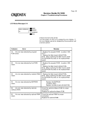
LCD Status Messages:3-5 Service Guide OL1200 Chapter 6 Troubleshooting Procedures Page: 98 A fault occurred in the printer. Code(nn) Error Remedy 10 An error was detected by optional software ROM. Note: When replacing the Main board, install the EEPROM mounted on to release the error display. Replace the optional RAM. Replace the Main board (AOLM-PCB). 50 An error was detected by font ROM check. - Replace the optional software ROM. 60 An error was detected...
LCD Status Messages:3-5 Service Guide OL1200 Chapter 6 Troubleshooting Procedures Page: 98 A fault occurred in the printer. Code(nn) Error Remedy 10 An error was detected by optional software ROM. Note: When replacing the Main board, install the EEPROM mounted on to release the error display. Replace the optional RAM. Replace the Main board (AOLM-PCB). 50 An error was detected by font ROM check. - Replace the optional software ROM. 60 An error was detected...
Service Manual
Page 150
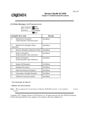
... replacing the Control board, install the EEPROM mounted on . - Control Copyright 1997, Okidata, Division of OKI America, Inc. Service Guide OL1200 Chapter 6 Troubleshooting Procedures Page: 99 LCD Status Messages: (4-4) Processor errors Exception Error code 4 Address Error Exception (Lead instruction, instruction fetch) Remedy See Below 5 Address Error Exception (Store instruction) See Below 6 Bus Error Exception (Instruction Fetch) See Below 7 Bus Error Exception (Load instruction, store instruction) See Below 7 Bus Error Exception (Load instruction, store instruction...
... replacing the Control board, install the EEPROM mounted on . - Control Copyright 1997, Okidata, Division of OKI America, Inc. Service Guide OL1200 Chapter 6 Troubleshooting Procedures Page: 99 LCD Status Messages: (4-4) Processor errors Exception Error code 4 Address Error Exception (Lead instruction, instruction fetch) Remedy See Below 5 Address Error Exception (Store instruction) See Below 6 Bus Error Exception (Instruction Fetch) See Below 7 Bus Error Exception (Load instruction, store instruction) See Below 7 Bus Error Exception (Load instruction, store instruction...

Service Manual
Page 169
... Control board. t Is the printer recovered? No Replace the Power/sensor board. See the OKIDATA Business Partner Exchange (BPX) for any updates to this material. (http://bpx.okidata.com) No Isolate the trouble by following the 2nd tray or envelope feeder maintenance manual. (See appendix C or D.) t YES END. t YES END. Service Guide OL1200 Chapter 6 Troubleshooting Procedures Page: 108 5 Synchronous serial I/O error (ERROR 74) or I/F time-out between the Control board and the optional tray connected...
... Control board. t Is the printer recovered? No Replace the Power/sensor board. See the OKIDATA Business Partner Exchange (BPX) for any updates to this material. (http://bpx.okidata.com) No Isolate the trouble by following the 2nd tray or envelope feeder maintenance manual. (See appendix C or D.) t YES END. t YES END. Service Guide OL1200 Chapter 6 Troubleshooting Procedures Page: 108 5 Synchronous serial I/O error (ERROR 74) or I/F time-out between the Control board and the optional tray connected...

Service Manual
Page 172
... menu level 2 coincide with the setting at the host side. YES END. No Replace the Control board. FLOW CONTROL BAUD RATE DATA BITS PARITY MIN. No Perform the loop back test using the loop test function in the system maintenance mode. (To make this test, it is necessary to port instead of the above items in the serial interface cable (broken or bent pin, broken wire)? Service Guide OL1200 Chapter 6 Troubleshooting Procedures Page...
... menu level 2 coincide with the setting at the host side. YES END. No Replace the Control board. FLOW CONTROL BAUD RATE DATA BITS PARITY MIN. No Perform the loop back test using the loop test function in the system maintenance mode. (To make this test, it is necessary to port instead of the above items in the serial interface cable (broken or bent pin, broken wire)? Service Guide OL1200 Chapter 6 Troubleshooting Procedures Page...

Service Manual
Page 177
.... Yes Replace the transfer roller. (See 3.3.36.) Has the trouble been removed? No Is paper of the LED head dirty? Yes End Note: After replacing the image drum cartridge, set the printer in the user maintenance mode by turning the power on the LED head for proper connection.) No Install the LED head properly. No Is the LED head installed properly? (Check connector HEAD1 (14P), HEAD2 (12P) of the developing and toner supply roller to User's Manual.) Image are light or...
.... Yes Replace the transfer roller. (See 3.3.36.) Has the trouble been removed? No Is paper of the LED head dirty? Yes End Note: After replacing the image drum cartridge, set the printer in the user maintenance mode by turning the power on the LED head for proper connection.) No Install the LED head properly. No Is the LED head installed properly? (Check connector HEAD1 (14P), HEAD2 (12P) of the developing and toner supply roller to User's Manual.) Image are light or...
Service Manual
Page 182
Replace the image drum cartridge. Replace the transfer roller. After replacing the image drum cartridge, set the printer in the user maintenance mode by turning the power on while pressing the MENU key, and reset the drum counter. (Refer to Users Manual.) 2 After replacing the fusing unit assy, set the printer in the engine maintenance mode by turning the power on while pressing the FORM FEED and ENTER keys, and reset the fuser counter. (Refer to this material. (http://bpx.okidata.com) All rights reserved. Replace the image drum cartridge. Notes: 1. See...
Replace the image drum cartridge. Replace the transfer roller. After replacing the image drum cartridge, set the printer in the user maintenance mode by turning the power on while pressing the MENU key, and reset the drum counter. (Refer to Users Manual.) 2 After replacing the fusing unit assy, set the printer in the engine maintenance mode by turning the power on while pressing the FORM FEED and ENTER keys, and reset the fuser counter. (Refer to this material. (http://bpx.okidata.com) All rights reserved. Replace the image drum cartridge. Notes: 1. See...

Service Manual
Page 183
... Adjust the contact plate contact to contact the contact assy properly. Set the LED head drive time. (Refer to Users Manual.) No Is the LED head installed properly? (Check connector HEAD1(14p), HEAD2 (12p) on the control board and PC Connector on while pressing the MENU key, and reset the drum counter. (Refer to Section 4.2.) No Replace the control board (OLCW- ) or power/sensor board. Service Guide OL1200 Chapter 6 Troubleshooting Procedures Page: 118...
... Adjust the contact plate contact to contact the contact assy properly. Set the LED head drive time. (Refer to Users Manual.) No Is the LED head installed properly? (Check connector HEAD1(14p), HEAD2 (12p) on the control board and PC Connector on while pressing the MENU key, and reset the drum counter. (Refer to Section 4.2.) No Replace the control board (OLCW- ) or power/sensor board. Service Guide OL1200 Chapter 6 Troubleshooting Procedures Page: 118...


