

Service Manual
Page 3
... Guide D ....3.3.13 Separator F ....3.3.14 Front Feeder Roller Assy ....3.3.15 Hopping Motor ....3.3.16 Front Feeder Paper End Sensor ....3.3.17 Main Chassis Unit ....3.3.18 Registration Roller ....3.3.19 Drum Motor ....3.3.20 Idle Gear ....3.3.21 Fusing Assy ....3.3.22 Fuser Pressure Roller ....3.3.23 Ep Lock Shaft ....3.3.24 Hopping roller Assy ....3.3.25 Outlet sensor lever ....3.3.26 Toner...
... Guide D ....3.3.13 Separator F ....3.3.14 Front Feeder Roller Assy ....3.3.15 Hopping Motor ....3.3.16 Front Feeder Paper End Sensor ....3.3.17 Main Chassis Unit ....3.3.18 Registration Roller ....3.3.19 Drum Motor ....3.3.20 Idle Gear ....3.3.21 Fusing Assy ....3.3.22 Fuser Pressure Roller ....3.3.23 Ep Lock Shaft ....3.3.24 Hopping roller Assy ....3.3.25 Outlet sensor lever ....3.3.26 Toner...

Service Manual
Page 12
...: Approx. 220W Idle: Approx. 100W Power save mode: 43 dB (A) or less (14) Consumables Toner cartridge kit 5,000 (5% duty) Image drum cartridge 30,000 (at room temperature 77°F (25°C) and rated voltage (120 VAC)] (7) Paper feed method Automatic feed or manual feed... sec. [at continuous printing) 20,000 (3 page/job) 15,000 (1 page/job) Standard sizes Letter Legal Executive Envelope A4 A5 B5 A6 - Service Guide OL1200 Chapter 1 Configuration Page: 5 1.4 Specification (1) Type Desk top (2) External dimensions Height 10.6 (270 mm) (excludes protruding Width 14.4 (366 mm) Portion) ...
...: Approx. 220W Idle: Approx. 100W Power save mode: 43 dB (A) or less (14) Consumables Toner cartridge kit 5,000 (5% duty) Image drum cartridge 30,000 (at room temperature 77°F (25°C) and rated voltage (120 VAC)] (7) Paper feed method Automatic feed or manual feed... sec. [at continuous printing) 20,000 (3 page/job) 15,000 (1 page/job) Standard sizes Letter Legal Executive Envelope A4 A5 B5 A6 - Service Guide OL1200 Chapter 1 Configuration Page: 5 1.4 Specification (1) Type Desk top (2) External dimensions Height 10.6 (270 mm) (excludes protruding Width 14.4 (366 mm) Portion) ...

Service Manual
Page 19
... according to each dot line to the LED head. (7) Host interface This printer has the following communication modes. - Various counter data (page counter, drum counter, fuser counter, etc.) - In addition, it transfers serially bit image data for each of the following interfaces to the printer.... - OKI HSP interface (Option) The single effective interface or the automatic interface select mode can be selected using the menu. RS232C serial interface - Nibble...
... according to each dot line to the LED head. (7) Host interface This printer has the following communication modes. - Various counter data (page counter, drum counter, fuser counter, etc.) - In addition, it transfers serially bit image data for each of the following interfaces to the printer.... - OKI HSP interface (Option) The single effective interface or the automatic interface select mode can be selected using the menu. RS232C serial interface - Nibble...

Service Manual
Page 25
See the OKIDATA Business Partner Exchange (BPX) for any updates to this material. (http://bpx.okidata.com) Copyright 1997, Okidata, Division of OKI America, Inc. All rights reserved. Service Guide OL1200 Chapter 2 Operation Description Page: 11 2.3 Relay/Driver Board (AOLC board) This board relays signals between the Control board and the Power/Sensor board and includes the registration motor and drum motor driver IC.
See the OKIDATA Business Partner Exchange (BPX) for any updates to this material. (http://bpx.okidata.com) Copyright 1997, Okidata, Division of OKI America, Inc. All rights reserved. Service Guide OL1200 Chapter 2 Operation Description Page: 11 2.3 Relay/Driver Board (AOLC board) This board relays signals between the Control board and the Power/Sensor board and includes the registration motor and drum motor driver IC.

Service Manual
Page 26
... of this mechanism. (5) LED head Image data for each dot line from the control board is applied to the image drum. (6) Fuser The fuser consists of a sensitive drum, a charger, and a developer. Service Guide OL1200 Chapter 2 Operation Description Page: 12 2.4 Electro-photographic Process 2.4.1 Electro-photographic process mechanism This mechanism prints image data from the...
... of this mechanism. (5) LED head Image data for each dot line from the control board is applied to the image drum. (6) Fuser The fuser consists of a sensitive drum, a charger, and a developer. Service Guide OL1200 Chapter 2 Operation Description Page: 12 2.4 Electro-photographic Process 2.4.1 Electro-photographic process mechanism This mechanism prints image data from the...
Service Manual
Page 28
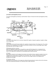
... charge, opposite in polarity to the toner, is attracted to the paper. As a result, the toner image formed on the image drum is transferred to the paper. 5 Temporary cleaning Residual toner that an electrostatic latent image associated with the print image is formed. 3 ...is applied to the cleaning roller by static electricity. At the same time, the residual toner on the image drum without being transferred is outlined below. Service Guide OL1200 Chapter 2 Operation Description Page: 13 2.4.2 Electro-photographic process The electro-photographic processing is made uniform by static ...
... charge, opposite in polarity to the toner, is attracted to the paper. As a result, the toner image formed on the image drum is transferred to the paper. 5 Temporary cleaning Residual toner that an electrostatic latent image associated with the print image is formed. 3 ...is applied to the cleaning roller by static electricity. At the same time, the residual toner on the image drum without being transferred is outlined below. Service Guide OL1200 Chapter 2 Operation Description Page: 13 2.4.2 Electro-photographic process The electro-photographic processing is made uniform by static ...

Service Manual
Page 34
Copyright 1997, Okidata, Division of OKI America, Inc. See the OKIDATA Business Partner Exchange (BPX) for any updates to the charge roller that is effected by applying a DC minus voltage to this material. (http://bpx.okidata.com) Service Guide OL1200 Chapter 2 Operation Description Page: 16 (3) Charging Charging is in contact with the image drum surface. All rights reserved.
Copyright 1997, Okidata, Division of OKI America, Inc. See the OKIDATA Business Partner Exchange (BPX) for any updates to the charge roller that is effected by applying a DC minus voltage to this material. (http://bpx.okidata.com) Service Guide OL1200 Chapter 2 Operation Description Page: 16 (3) Charging Charging is in contact with the image drum surface. All rights reserved.
Service Manual
Page 35
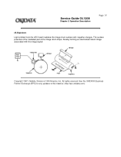
Copyright 1997, Okidata, Division of the image drum drops, thereby forming an electrostatic latent image associated with negative charges. See the OKIDATA Business Partner Exchange (BPX) for any updates to this material. (http://bpx.okidata.com) Service Guide OL1200 Chapter 2 Operation Description Page: 17 (4) Exposure Light emitted from the LED head irradiates the image drum surface with the image signal. The surface potential of the irradiated part of OKI America, Inc. All rights reserved.
Copyright 1997, Okidata, Division of the image drum drops, thereby forming an electrostatic latent image associated with negative charges. See the OKIDATA Business Partner Exchange (BPX) for any updates to this material. (http://bpx.okidata.com) Service Guide OL1200 Chapter 2 Operation Description Page: 17 (4) Exposure Light emitted from the LED head irradiates the image drum surface with the image signal. The surface potential of the irradiated part of OKI America, Inc. All rights reserved.
Service Manual
Page 36
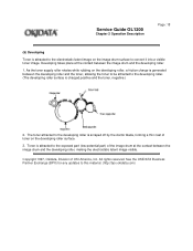
...Exchange (BPX) for any updates to convert it into a visible toner image. Developing takes place at the contact between the image drum and the developing roller, making the electrostatic latent image visible. The toner attracted to the developing roller is attracted to the exposed ...electrostatic latent image on the developing roller surface. 3. Toner is scraped off by the doctor blade, forming a thin coat of OKI America, Inc. Service Guide OL1200 Chapter 2 Operation Description Page: 18 (5) Developing Toner is charged positive and the toner, negative.) 2. As the toner supply roller...
...Exchange (BPX) for any updates to convert it into a visible toner image. Developing takes place at the contact between the image drum and the developing roller, making the electrostatic latent image visible. The toner attracted to the developing roller is attracted to the exposed ...electrostatic latent image on the developing roller surface. 3. Toner is scraped off by the doctor blade, forming a thin coat of OKI America, Inc. Service Guide OL1200 Chapter 2 Operation Description Page: 18 (5) Developing Toner is charged positive and the toner, negative.) 2. As the toner supply roller...

Service Manual
Page 37
The application of a high positive voltage from its reverse side. All rights reserved. Service Guide OL1200 Chapter 2 Operation Description Page: 19 (6) Transfer The transfer roller is composed of conductive sponge material and is transferred to the upper side of the paper ...) for any updates to the paper at the contact between the transfer roller and the paper. Copyright 1997, Okidata, Division of OKI America, Inc. Paper is placed over the image drum surface, and a positive charge, opposite in polarity to the toner, is applied to the paper from the power supply to the...
The application of a high positive voltage from its reverse side. All rights reserved. Service Guide OL1200 Chapter 2 Operation Description Page: 19 (6) Transfer The transfer roller is composed of conductive sponge material and is transferred to the upper side of the paper ...) for any updates to the paper at the contact between the transfer roller and the paper. Copyright 1997, Okidata, Division of OKI America, Inc. Paper is placed over the image drum surface, and a positive charge, opposite in polarity to the toner, is applied to the paper from the power supply to the...

Service Manual
Page 39
All rights reserved. See the OKIDATA Business Partner Exchange (BPX) for any updates to clean the image drum surface. Copyright 1997, Okidata, Division of the transfer, residual toner on the image drum is attracted to the cleaning roller temporarily by static electricity to this material. (http://bpx.okidata.com) Service Guide OL1200 Chapter 2 Operation Description Page: 21 (8) Cleaning After the end of OKI America, Inc.
All rights reserved. See the OKIDATA Business Partner Exchange (BPX) for any updates to clean the image drum surface. Copyright 1997, Okidata, Division of the transfer, residual toner on the image drum is attracted to the cleaning roller temporarily by static electricity to this material. (http://bpx.okidata.com) Service Guide OL1200 Chapter 2 Operation Description Page: 21 (8) Cleaning After the end of OKI America, Inc.

Service Manual
Page 40
...or more and the printout operation ends Changes in the following cases: - When the number of OKI America, Inc. In warming up at power-on time - All rights reserved. Service Guide OL1200 Chapter 2 Operation Description Page: 22 (9) Cleaning of rollers The charge roller, transfer roller and... cleaning roller are cleaned in bias voltage applied to each roller move adhesive toner from the roller to the image drum and return it to this material...
...or more and the printout operation ends Changes in the following cases: - When the number of OKI America, Inc. In warming up at power-on time - All rights reserved. Service Guide OL1200 Chapter 2 Operation Description Page: 22 (9) Cleaning of rollers The charge roller, transfer roller and... cleaning roller are cleaned in bias voltage applied to each roller move adhesive toner from the roller to the image drum and return it to this material...

Service Manual
Page 45
... activated. - When there is no change with the toner sensor for any updates to this material. (http://bpx.okidata.com) Copyright 1997, Okidata, Division of OKI America, Inc. All rights reserved. TONER FULL state TONER LOW state - When the toner full state is detected 2 times consecutively, Toner Low is in halt...
... activated. - When there is no change with the toner sensor for any updates to this material. (http://bpx.okidata.com) Copyright 1997, Okidata, Division of OKI America, Inc. All rights reserved. TONER FULL state TONER LOW state - When the toner full state is detected 2 times consecutively, Toner Low is in halt...
Service Manual
Page 56
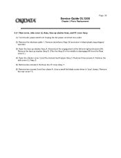
... (4) Open the stacker cover 2 and the manual feed hopper Assy 3. Remove three screws 4. Remove the side cover (L) Assy 5. (5) Remove two screws 6. Service Guide OL1200 Chapter 3 Parts Replacement Page: 36 3.3.1 Rear cover, side cover (L) Assy, face-up stacker Assy, and I /F cover Assy 7. (6) Remove two screws 9 and four... (2) Remove the interface cable 1. Remove the face-up stacker Assy 8. Disconnect the engagement at the left and right protrusions 8A . Remove drum/toner Assy 2A and store in black plastic bag shipped w/printer. (3) Open the face-up stacker Assy 8. (Flex the Assy 8 in...
... (4) Open the stacker cover 2 and the manual feed hopper Assy 3. Remove three screws 4. Remove the side cover (L) Assy 5. (5) Remove two screws 6. Service Guide OL1200 Chapter 3 Parts Replacement Page: 36 3.3.1 Rear cover, side cover (L) Assy, face-up stacker Assy, and I /F cover Assy 7. (6) Remove two screws 9 and four... (2) Remove the interface cable 1. Remove the face-up stacker Assy 8. Disconnect the engagement at the left and right protrusions 8A . Remove drum/toner Assy 2A and store in black plastic bag shipped w/printer. (3) Open the face-up stacker Assy 8. (Flex the Assy 8 in...

Service Manual
Page 85
... damage spring. (7) Remove EP lock spring 5 and then remove ED lock lever 6. (8) Release two latches and remove motor Assy 7. (9) Remove two screws 8 and then remove drum motor 9 and heat sink. (10) Remove two screws 10 and then remove registration motor A. Unplug the AC power cord from the outlet. (2) Remove the main... 1 and pull out it toward the right. (At this time, idle gear H (2) is also removed.) (6) Remove spring 3 and then remove pressure release lever 4. Service Guide OL1200 Chapter 3 Parts Replacement Page: 54 3.3.19 Drum motor (1) Turn the AC power switch off.
... damage spring. (7) Remove EP lock spring 5 and then remove ED lock lever 6. (8) Release two latches and remove motor Assy 7. (9) Remove two screws 8 and then remove drum motor 9 and heat sink. (10) Remove two screws 10 and then remove registration motor A. Unplug the AC power cord from the outlet. (2) Remove the main... 1 and pull out it toward the right. (At this time, idle gear H (2) is also removed.) (6) Remove spring 3 and then remove pressure release lever 4. Service Guide OL1200 Chapter 3 Parts Replacement Page: 54 3.3.19 Drum motor (1) Turn the AC power switch off.

Service Manual
Page 112
...- Engine reset Copyright 1997, Okidata, Division of envelope feeder download table - Hex dump - Page count display - Drum count display - Selection of OKI America, Inc. Service Guide OL1200 Chapter 4 Adjustment Page: 73 4.1 Maintenance Modes And Functions - User maintenance mode To enter the user maintenance mode...service persons and it should not be released to the end-users. Head drive time setting - Printing start position setting - Drum counter total display - Setting of second tray paper feed length - Setting of front feeder paper feed length - Selection of second...
...- Engine reset Copyright 1997, Okidata, Division of envelope feeder download table - Hex dump - Page count display - Drum count display - Selection of OKI America, Inc. Service Guide OL1200 Chapter 4 Adjustment Page: 73 4.1 Maintenance Modes And Functions - User maintenance mode To enter the user maintenance mode...service persons and it should not be released to the end-users. Head drive time setting - Printing start position setting - Drum counter total display - Setting of second tray paper feed length - Setting of front feeder paper feed length - Selection of second...

Service Manual
Page 113
...of resetting. (4) Operator panel menu disable - This function resets the drum life data when the user replaces the image drum unit. - The user maintenance mode provides the following functions: (1) Menu...This function is for any updates to the factory default values. All rights reserved. Service Guide OL1200 Chapter 4 Adjustment Page: 74 4.1.1 User maintenance mode - If the received data is less...25 mm steps in hexadecimal notation to adjust the printing start position within the range of OKI America, Inc. This function is used to the printer. - See the OKIDATA Business...
...of resetting. (4) Operator panel menu disable - This function resets the drum life data when the user replaces the image drum unit. - The user maintenance mode provides the following functions: (1) Menu...This function is for any updates to the factory default values. All rights reserved. Service Guide OL1200 Chapter 4 Adjustment Page: 74 4.1.1 User maintenance mode - If the received data is less...25 mm steps in hexadecimal notation to adjust the printing start position within the range of OKI America, Inc. This function is used to the printer. - See the OKIDATA Business...

Service Manual
Page 118
...feeder. (10) Selection of High Capacity Second Paper Feeder paper feed length - The method for function selection. - Service Guide OL1200 Chapter 4 Adjustment Page: 78 4.1.3 Engine maintenance mode - This function selects the download table for the High Capacity Second Paper Feeder. (9) Setting... of drum revolutions in the unit counted at the engine. (12) Fuser count reset - This function selects the download table for the Power envelope...
...feeder. (10) Selection of High Capacity Second Paper Feeder paper feed length - The method for function selection. - Service Guide OL1200 Chapter 4 Adjustment Page: 78 4.1.3 Engine maintenance mode - This function selects the download table for the High Capacity Second Paper Feeder. (9) Setting... of drum revolutions in the unit counted at the engine. (12) Fuser count reset - This function selects the download table for the Power envelope...
Service Manual
Page 123
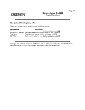
...time. (Refer to Chapter 4.2.1) Reset the image drum counter. (Refer to User's manual) Reset the fuser counter. (Refer to Chapter 4.2.2) Set the LED head drive time. (Refer to this material. (http://bpx.okidata.com) Service Guide OL1200 Chapter 4 Adjustment Page: 81 4.2 Adjustment When... Replacing A Part Adjustment necessary when replacing one of OKI America, Inc. See the OKIDATA Business Partner Exchange (BPX) for any updates to Chapter 4.2.1)...
...time. (Refer to Chapter 4.2.1) Reset the image drum counter. (Refer to User's manual) Reset the fuser counter. (Refer to Chapter 4.2.2) Set the LED head drive time. (Refer to this material. (http://bpx.okidata.com) Service Guide OL1200 Chapter 4 Adjustment Page: 81 4.2 Adjustment When... Replacing A Part Adjustment necessary when replacing one of OKI America, Inc. See the OKIDATA Business Partner Exchange (BPX) for any updates to Chapter 4.2.1)...
Service Manual
Page 129
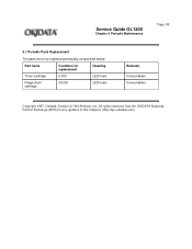
Service Guide OL1200 Chapter 5 Periodic Maintenance Page: 85 5.1 Periodic Parts Replacement The parts are to be replaced periodically as specified below: Part name Condition for any updates to this material. (http://bpx.okidata.com) See the OKIDATA Business Partner Exchange (BPX) for replacement Cleaning Toner cartridge 5,000 LED head. Image drum cartridge 30,000 LED head. Remarks Consumables Consumables Copyright 1997, Okidata, Division of OKI America, Inc. All rights reserved.
Service Guide OL1200 Chapter 5 Periodic Maintenance Page: 85 5.1 Periodic Parts Replacement The parts are to be replaced periodically as specified below: Part name Condition for any updates to this material. (http://bpx.okidata.com) See the OKIDATA Business Partner Exchange (BPX) for replacement Cleaning Toner cartridge 5,000 LED head. Image drum cartridge 30,000 LED head. Remarks Consumables Consumables Copyright 1997, Okidata, Division of OKI America, Inc. All rights reserved.


