
Installation Guide
Page 9
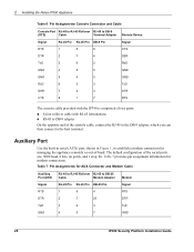
Tables Table 1 Command-Line Conventions 14 Table 2 Text Conventions 15 Table 3 Specifications for the IP390 Platform 17 Table 4 PMC Network Interface Card Slots 19 Table 5 System Status LEDs 20 Table 6 Pin Assignments Console Connector and Cable 28 Table 7 Pin Assignments for AUX Connector and Modem Cable 28 IP390 Security Platform Installation Guide 9
Tables Table 1 Command-Line Conventions 14 Table 2 Text Conventions 15 Table 3 Specifications for the IP390 Platform 17 Table 4 PMC Network Interface Card Slots 19 Table 5 System Status LEDs 20 Table 6 Pin Assignments Console Connector and Cable 28 Table 7 Pin Assignments for AUX Connector and Modem Cable 28 IP390 Security Platform Installation Guide 9
Installation Guide
Page 18
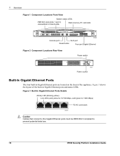
... of the appliance. Figure 3 Built-In Gigabit Ethernet Ports Details Activity LED (blinking yellow) Link LED (solid yellow for 10/100 Mbps, solid green for 1000 Mbps) 00547 RJ-45 connectors Caution Cables that connect to the Gigabit Ethernet ports must be IEEE 802.3 compliant to prevent potential data loss. 18 IP390 Security Platform...
... of the appliance. Figure 3 Built-In Gigabit Ethernet Ports Details Activity LED (blinking yellow) Link LED (solid yellow for 10/100 Mbps, solid green for 1000 Mbps) 00547 RJ-45 connectors Caution Cables that connect to the Gigabit Ethernet ports must be IEEE 802.3 compliant to prevent potential data loss. 18 IP390 Security Platform...

Installation Guide
Page 25
... Port If you no longer need the console connection. IP390 Security Platform Installation Guide 25 the serial (AUX) port is Cisco compatible. You can use any standard VT100-compatible terminal with a null-modem cable 1. Use only the RJ-45 port labeled Console on the front panel of the appliance. 2. Plug the other end of the cord...
... Port If you no longer need the console connection. IP390 Security Platform Installation Guide 25 the serial (AUX) port is Cisco compatible. You can use any standard VT100-compatible terminal with a null-modem cable 1. Use only the RJ-45 port labeled Console on the front panel of the appliance. 2. Plug the other end of the cord...
Installation Guide
Page 26
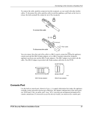
... the IP390. IP390 00525 Console port For cable pin assignments for IP390 console and auxiliary port connections. For information about contacting Nokia to order the kit, see "Console Port" on page 3. Connect the other end of your appliance. 2 Installing the Nokia IP390 Appliance One RJ-45 termination has a retractable shroud that Nokia provides with IP390 appliances includes a latching mechanism used to secure the cable to the console port...
... the IP390. IP390 00525 Console port For cable pin assignments for IP390 console and auxiliary port connections. For information about contacting Nokia to order the kit, see "Console Port" on page 3. Connect the other end of your appliance. 2 Installing the Nokia IP390 Appliance One RJ-45 termination has a retractable shroud that Nokia provides with IP390 appliances includes a latching mechanism used to secure the cable to the console port...
Installation Guide
Page 27
... is provided with Nokia modem cable kits for console connections. Table 6 provides pin assignment information for the IP390. IP390 Security Platform Installation Guide 27 The DB-25 adaptor is provided with the cable. If you need to release the latch, and pull the connector out of the receptacle. To disconnect the cable, push the cable toward the appliance, pull back...
... is provided with Nokia modem cable kits for console connections. Table 6 provides pin assignment information for the IP390. IP390 Security Platform Installation Guide 27 The DB-25 adaptor is provided with the cable. If you need to release the latch, and pull the connector out of the receptacle. To disconnect the cable, push the cable toward the appliance, pull back...
Installation Guide
Page 28
... for managing the appliance remotely or out-of the console cable, connect the RJ-45 to the DB-9 adapter, which you can then connect to DB-25 Cable Modem Adapter Modem Signal RJ-45 Pin RJ-45 Pin DB-25 Pin Signal RTS 1 8 4 RTS DTR 2 7 20 DTR TxD 3 6 3 TxD GND 4 5 7 GND 28 IP390 Security Platform Installation...
... for managing the appliance remotely or out-of the console cable, connect the RJ-45 to the DB-9 adapter, which you can then connect to DB-25 Cable Modem Adapter Modem Signal RJ-45 Pin RJ-45 Pin DB-25 Pin Signal RTS 1 8 4 RTS DTR 2 7 20 DTR TxD 3 6 3 TxD GND 4 5 7 GND 28 IP390 Security Platform Installation...
Installation Guide
Page 33
... your network is completely plugged in "Nokia Contact Information" on the console, check the console port and console display connections to configure and monitor your appliance. 2. Using Nokia Network Voyager If the Hostname? prompts, verify that the serial cable is configured to respond to enter the...configure the appliance with an incorrect host name and IP address (this section. Enter the following: rm /config/active or mv /config/active /config/active.old d. For more information about how to prevent the DHCP client from restarting. 4. IP390 Security Platform Installation ...
... your network is completely plugged in "Nokia Contact Information" on the console, check the console port and console display connections to configure and monitor your appliance. 2. Using Nokia Network Voyager If the Hostname? prompts, verify that the serial cable is configured to respond to enter the...configure the appliance with an incorrect host name and IP address (this section. Enter the following: rm /config/active or mv /config/active /config/active.old d. For more information about how to prevent the DHCP client from restarting. 4. IP390 Security Platform Installation ...
Installation Guide
Page 75
... Log in to the Console Port-No Error Message Two laptop computers (using terminal emulation programs) or terminals should be able to communicate back to back in this is with the terminal or cable and not the appliance. Problem Not connected with the IP390 appliance. Solution The IP390 appliance does not use flow control. IP390 Security Platform Installation Guide...
... Log in to the Console Port-No Error Message Two laptop computers (using terminal emulation programs) or terminals should be able to communicate back to back in this is with the terminal or cable and not the appliance. Problem Not connected with the IP390 appliance. Solution The IP390 appliance does not use flow control. IP390 Security Platform Installation Guide...
Installation Guide
Page 78
...Problem No link light. Use a crossover cable between an IP390 appliance and a host, and a straight-through cable if you are connecting to verify the interface configuration and fix it if necessary. Solution Use a crossover Ethernet cable if you are connecting directly to verify the... But Console Access Works Problem Using the wrong Ethernet cable. Common Ethernet Problems-Connectivity with the slot on each end of the Ethernet connection (10 Mbps or 100Mbps). 78 IP390 Security Platform Installation Guide Problem Solid data and activity LED. Contact the appropriate Nokia customer...
...Problem No link light. Use a crossover cable between an IP390 appliance and a host, and a straight-through cable if you are connecting to verify the interface configuration and fix it if necessary. Solution Use a crossover Ethernet cable if you are connecting directly to verify the... But Console Access Works Problem Using the wrong Ethernet cable. Common Ethernet Problems-Connectivity with the slot on each end of the Ethernet connection (10 Mbps or 100Mbps). 78 IP390 Security Platform Installation Guide Problem Solid data and activity LED. Contact the appropriate Nokia customer...
Installation Guide
Page 93
...appliance 17 auxiliary port connecting to the 26 pin assignments 28 B battery holder 73 location 72 replacing 70 built-in Gigabit Ethernet ports 18 C cables... 21 using the 35 compact flash memory card (internal) Nokia IPSO storage 17 replacing 57 compliance information 89 declaration of conformity ...92 statements 90 component locations 17 connections auxiliary port 26 console port 26 Ethernet NICs 38 Gigabit Ethernet NIC, fiber-... Ethernet NICs cable pin assignments 39 connecting to 38 crossover-cable pin connections 39 front panel 38 IEEE 802.3ab compliance 38 LEDs 38 IP390 Security Platform Installation...
...appliance 17 auxiliary port connecting to the 26 pin assignments 28 B battery holder 73 location 72 replacing 70 built-in Gigabit Ethernet ports 18 C cables... 21 using the 35 compact flash memory card (internal) Nokia IPSO storage 17 replacing 57 compliance information 89 declaration of conformity ...92 statements 90 component locations 17 connections auxiliary port 26 console port 26 Ethernet NICs 38 Gigabit Ethernet NIC, fiber-... Ethernet NICs cable pin assignments 39 connecting to 38 crossover-cable pin connections 39 front panel 38 IEEE 802.3ab compliance 38 LEDs 38 IP390 Security Platform Installation...