
Installation Guide
Page 6
... Command-Line Interface to Manage Your Security Platform 50 Using Nokia Horizon Manager 51 3 Installing the Nokia IP1200 Series Security Platform 53 Rack Mounting the Security Platform 53 Before You Begin 54 4 Installing and Replacing Network Interface Cards 61 Removing, Installing, and Replacing NICs 62 Before You Begin 63 Configuring and Activating Interfaces 70 Monitoring Network Interface Cards 71 5 Connecting PMC Network Interface Cards 73 Four-Port and Dual-Port 10/100 Ethernet NICs 75 10/100 Ethernet NIC Features 75 Ethernet NIC Connectors and Cables 77 Dual-Port Fiber...
... Command-Line Interface to Manage Your Security Platform 50 Using Nokia Horizon Manager 51 3 Installing the Nokia IP1200 Series Security Platform 53 Rack Mounting the Security Platform 53 Before You Begin 54 4 Installing and Replacing Network Interface Cards 61 Removing, Installing, and Replacing NICs 62 Before You Begin 63 Configuring and Activating Interfaces 70 Monitoring Network Interface Cards 71 5 Connecting PMC Network Interface Cards 73 Four-Port and Dual-Port 10/100 Ethernet NICs 75 10/100 Ethernet NIC Features 75 Ethernet NIC Connectors and Cables 77 Dual-Port Fiber...

Installation Guide
Page 11
... Front View 23 Figure 2 Ethernet Management Ports Details 24 Figure 3 Pin Assignments for Console Connection 26 Figure 4 Pin Assignments for Modem Connection 27 Figure 5 Nokia IP1200 Series Security Platform System Status LEDs 28 Figure 6 Hard-Disk Drive Front Panel 31 Figure 7 Power Supply and Fan Unit Locations 33 Figure 8 Power Supply, Cooling Fan, and Power Switch Locations 34 Figure 9 Power Switch Location 42 Figure 10 Nokia Network Voyager Reference Access Points Example 49 Figure 11 Rack-Mounting...
... Front View 23 Figure 2 Ethernet Management Ports Details 24 Figure 3 Pin Assignments for Console Connection 26 Figure 4 Pin Assignments for Modem Connection 27 Figure 5 Nokia IP1200 Series Security Platform System Status LEDs 28 Figure 6 Hard-Disk Drive Front Panel 31 Figure 7 Power Supply and Fan Unit Locations 33 Figure 8 Power Supply, Cooling Fan, and Power Switch Locations 34 Figure 9 Power Switch Location 42 Figure 10 Nokia Network Voyager Reference Access Points Example 49 Figure 11 Rack-Mounting...
Installation Guide
Page 16
... install or replace memory, hard disk drives, and power supplies. „ Appendix A, "Technical Specifications" provides technical specifications such as a room or equipment closet, might occur because of a physical hazard, or that either bodily injury might occur because of equipment damage. Conventions This Guide Uses The following sections describe the conventions this Guide „ Chapter 5, "Connecting PMC Network Interface Cards" describes how to connect to and use each of the supported...
... install or replace memory, hard disk drives, and power supplies. „ Appendix A, "Technical Specifications" provides technical specifications such as a room or equipment closet, might occur because of a physical hazard, or that either bodily injury might occur because of equipment damage. Conventions This Guide Uses The following sections describe the conventions this Guide „ Chapter 5, "Connecting PMC Network Interface Cards" describes how to connect to and use each of the supported...
Installation Guide
Page 20
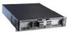
... a serviceable slide-out tray into the chassis design. 1 Overview Table 2 Nokia IP1200 Series Security Platform Specifics IP Security Platform IPSO Version Software Initial Memory Upgradeable Configuration RAM IP1260 v3.7 or later Check Point NG FP3 (hf2) Nokia Secure Access System v1.02 or later 1 GB 2 GB IP1220 v3.8 or later Check Point NG with Nokia and partner applications. In addition, the IP1200 Series 20 Nokia IP1200 Series Security Platform Installation Guide These network interfaces provide exceptional data forwarding and...
... a serviceable slide-out tray into the chassis design. 1 Overview Table 2 Nokia IP1200 Series Security Platform Specifics IP Security Platform IPSO Version Software Initial Memory Upgradeable Configuration RAM IP1260 v3.7 or later Check Point NG FP3 (hf2) Nokia Secure Access System v1.02 or later 1 GB 2 GB IP1220 v3.8 or later Check Point NG with Nokia and partner applications. In addition, the IP1200 Series 20 Nokia IP1200 Series Security Platform Installation Guide These network interfaces provide exceptional data forwarding and...

Installation Guide
Page 21
... intranet and access routers in security applications. Everything that enables you can accomplish with Network Nokia IP1200 Series Security Platform Installation Guide 21 For information about how to access Network Voyager and the related reference materials, see "Using Nokia Network Voyager to access the Network Voyager interface. As a network device, the IP1200 Series supports a comprehensive suite of the four Ethernet management ports to Manage Your Security Platform" on the IP1200 Series and enabled through the IPSO operating system...
... intranet and access routers in security applications. Everything that enables you can accomplish with Network Nokia IP1200 Series Security Platform Installation Guide 21 For information about how to access Network Voyager and the related reference materials, see "Using Nokia Network Voyager to access the Network Voyager interface. As a network device, the IP1200 Series supports a comprehensive suite of the four Ethernet management ports to Manage Your Security Platform" on the IP1200 Series and enabled through the IPSO operating system...
Installation Guide
Page 25
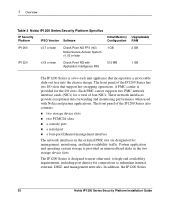
... Series Security Platform Installation Guide 25 Nokia IP1200 Series Security Platform Overview Table 3 PMC Expansion Slots NIC Type Interface LAN WAN For details, see... The Nokia Global Support Services group can only provide support for Nokia products that use Nokia-approved accessories. Four-port Ethernet X (10 or 100 Mbps) "Four-Port and Dual-Port 10/100 Ethernet NICs" on page 75 Dual-port Ethernet X (10 or 100 Mbps) "Four-Port and Dual-Port 10/100 Ethernet NICs" on page 75 Dual-port fiber-optic X Gigabit Ethernet "Dual-Port Fiber-Optic Gigabit Ethernet...
... Series Security Platform Installation Guide 25 Nokia IP1200 Series Security Platform Overview Table 3 PMC Expansion Slots NIC Type Interface LAN WAN For details, see... The Nokia Global Support Services group can only provide support for Nokia products that use Nokia-approved accessories. Four-port Ethernet X (10 or 100 Mbps) "Four-Port and Dual-Port 10/100 Ethernet NICs" on page 75 Dual-port Ethernet X (10 or 100 Mbps) "Four-Port and Dual-Port 10/100 Ethernet NICs" on page 75 Dual-port fiber-optic X Gigabit Ethernet "Dual-Port Fiber-Optic Gigabit Ethernet...

Installation Guide
Page 39
...: „ Using a Console Connection „ Connecting Power and Turning the Power On „ Performing the Initial Configuration „ Connecting Network Interfaces „ Accessing Nokia Network Voyager Reference Information „ Using Nokia Horizon Manager For information about how to use the DHCP client for initial configuration, see the Read Me First document, Using DHCP to the admin account. You can perform the initial configuration in two ways: „ Configure a DHCP server to provide the initial configuration information the first time the appliance is...
...: „ Using a Console Connection „ Connecting Power and Turning the Power On „ Performing the Initial Configuration „ Connecting Network Interfaces „ Accessing Nokia Network Voyager Reference Information „ Using Nokia Horizon Manager For information about how to use the DHCP client for initial configuration, see the Read Me First document, Using DHCP to the admin account. You can perform the initial configuration in two ways: „ Configure a DHCP server to provide the initial configuration information the first time the appliance is...
Installation Guide
Page 43
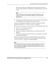
... that the power supply fans are still not running, or if the power LED does not illuminate, contact your Nokia service provider or Nokia Support as listed in from the front of the appliance to 264]) and configures itself appropriately. 4. Check the power LED (the Nokia logo) on , the Fault LED illuminates. If the fans are not running after you press the power switch. If two power supplies are not...
... that the power supply fans are still not running, or if the power LED does not illuminate, contact your Nokia service provider or Nokia Support as listed in from the front of the appliance to 264]) and configures itself appropriately. 4. Check the power LED (the Nokia logo) on , the Fault LED illuminates. If the fans are not running after you press the power switch. If two power supplies are not...

Installation Guide
Page 46
... also connect the remaining LAN and WAN interface cables at least one of the four front-panel Ethernet management ports for the first port of a dual-port Ethernet NIC in Chapter 2, "Performing the Initial Configuration." Connecting Network Interfaces Connect at this connection. 46 Nokia IP1200 Series Security Platform Installation Guide Note Nokia recommends that you are numbered eth-s3p1 through eth-s3p4. This interface is configured during the initial configuration process, which is : nic_type-sslot_num/ssubslot_numpport_num For example...
... also connect the remaining LAN and WAN interface cables at least one of the four front-panel Ethernet management ports for the first port of a dual-port Ethernet NIC in Chapter 2, "Performing the Initial Configuration." Connecting Network Interfaces Connect at this connection. 46 Nokia IP1200 Series Security Platform Installation Guide Note Nokia recommends that you are numbered eth-s3p1 through eth-s3p4. This interface is configured during the initial configuration process, which is : nic_type-sslot_num/ssubslot_numpport_num For example...

Installation Guide
Page 47
... required for the destination Gigabit Ethernet device. For details, see "Fiber-Optic Gigabit Ethernet NIC Connectors and Cables" on page 89. For details, see "Accessing Nokia Network Voyager Reference Information" and "Nokia Network Voyager Inline Help" on page 86. „ To connect X.21 devices, use X.21 DB-26 to configure or monitor your IP1200 Series. Using Nokia Network Voyager to Manage Your Security Platform Use Nokia Network Voyager to V.35 adapter cable. To open Nokia Network Voyager 1. For additional...
... required for the destination Gigabit Ethernet device. For details, see "Fiber-Optic Gigabit Ethernet NIC Connectors and Cables" on page 89. For details, see "Accessing Nokia Network Voyager Reference Information" and "Nokia Network Voyager Inline Help" on page 86. „ To connect X.21 devices, use X.21 DB-26 to configure or monitor your IP1200 Series. Using Nokia Network Voyager to Manage Your Security Platform Use Nokia Network Voyager to V.35 adapter cable. To open Nokia Network Voyager 1. For additional...
Installation Guide
Page 48
... the appropriate installation guide. Accessing Nokia Network Voyager Reference Information As you use . Confirm the information you to use Nokia Network Voyager, the Nokia Network Voyager Reference Guide and Voyager inline help are available for you entered during the initial configuration and check that all cables are prompted to enter the admin username and the password you entered when you might not have a physical network connection between the host and your appliance, or...
... the appropriate installation guide. Accessing Nokia Network Voyager Reference Information As you use . Confirm the information you to use Nokia Network Voyager, the Nokia Network Voyager Reference Guide and Voyager inline help are available for you entered during the initial configuration and check that all cables are prompted to enter the admin username and the password you entered when you might not have a physical network connection between the host and your appliance, or...
Installation Guide
Page 78
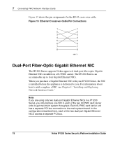
... Security Platform Installation Guide Each 6U PMC card carrier unit has a separate PCI bus connection to add or replace a NIC, see Chapter 4, "Installing and Replacing Network Interface Cards." For information about how to the main system board. 5 Connecting PMC Network Interface Cards Figure 15 shows the pin assignments for the RJ-45 cross-over cable. Figure 15 Ethernet Crossover-Cable Pin Connections 1 1 2 2 3 3 4 4 5 5 6 6 7 7 8 8 00017.1 Dual-Port Fiber-Optic Gigabit Ethernet NIC The IP1200 Series supports Nokia-approved, dual-port fiber-optic Gigabit Ethernet...
... Security Platform Installation Guide Each 6U PMC card carrier unit has a separate PCI bus connection to add or replace a NIC, see Chapter 4, "Installing and Replacing Network Interface Cards." For information about how to the main system board. 5 Connecting PMC Network Interface Cards Figure 15 shows the pin assignments for the RJ-45 cross-over cable. Figure 15 Ethernet Crossover-Cable Pin Connections 1 1 2 2 3 3 4 4 5 5 6 6 7 7 8 8 00017.1 Dual-Port Fiber-Optic Gigabit Ethernet NIC The IP1200 Series supports Nokia-approved, dual-port fiber-optic Gigabit Ethernet...
Installation Guide
Page 79
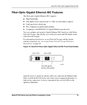
Nokia IP1200 Series Security Platform Installation Guide 79 Specifically, you set the port speed and full-duplex mode with Nokia Network Voyager. As data is turned on and the cables are connected, the Ethernet link LEDs on both the IP1200 Series and on the remote equipment illuminate to access Network Voyager and the related reference materials, see "Accessing Nokia Network Voyager Reference Information" on the appliance illuminate. For information about how to indicate the connection. Dual-Port Fiber-Optic Gigabit Ethernet NIC Fiber-Optic Gigabit Ethernet NIC...
Nokia IP1200 Series Security Platform Installation Guide 79 Specifically, you set the port speed and full-duplex mode with Nokia Network Voyager. As data is turned on and the cables are connected, the Ethernet link LEDs on both the IP1200 Series and on the remote equipment illuminate to access Network Voyager and the related reference materials, see "Accessing Nokia Network Voyager Reference Information" on the appliance illuminate. For information about how to indicate the connection. Dual-Port Fiber-Optic Gigabit Ethernet NIC Fiber-Optic Gigabit Ethernet NIC...
Installation Guide
Page 101
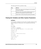
Variables The following syntax: printenv For example: BOOTMGR[93]> printenv NOKIA IPSO BOOTMGR VERSION=3.7 07.05.2003-130000 autoboot: YES testboot: NO bootwait: 3 boot-file: /image/current/kernel boot-flags: boot-device: wd0 vendor: Nokia model: IP bmslice: 4 Nokia IP1200 Series Security Platform Installation Guide 101 Viewing the Variables and Other System Parameters printenv Use the printenv command to access the manager. Flag -d -s -v Meaning Debug mode-enters the kernel debugger as soon as...
Variables The following syntax: printenv For example: BOOTMGR[93]> printenv NOKIA IPSO BOOTMGR VERSION=3.7 07.05.2003-130000 autoboot: YES testboot: NO bootwait: 3 boot-file: /image/current/kernel boot-flags: boot-device: wd0 vendor: Nokia model: IP bmslice: 4 Nokia IP1200 Series Security Platform Installation Guide 101 Viewing the Variables and Other System Parameters printenv Use the printenv command to access the manager. Flag -d -s -v Meaning Debug mode-enters the kernel debugger as soon as...
Installation Guide
Page 103
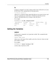
...: setenv name value where name is the name of the variable, and value is the new value you want to look at, and directory is the device that device. Nokia IP1200 Series Security Platform Installation Guide 103 Variables ls Use the ls command to view the contents of directories on the wd0 device. For example: BOOTMGR[2]> setenv autoboot YES sets the value of autoboot to...
...: setenv name value where name is the name of the variable, and value is the new value you want to look at, and directory is the device that device. Nokia IP1200 Series Security Platform Installation Guide 103 Variables ls Use the ls command to view the contents of directories on the wd0 device. For example: BOOTMGR[2]> setenv autoboot YES sets the value of autoboot to...
Installation Guide
Page 114
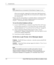
.... Note Use the full installation procedure to create a new factory default configuration. 3. Create the new default configuration. For information about how to the IP1200 Series as admin by using Nokia Network Voyager. 7 Troubleshooting Note Blank passwords are not accepted in Chapter 2, "Performing the Initial Configuration." Finally, return the entire database to its default settings to restore or reload an IP1200 Series. The new system completely replaces the contents of the drive and...
.... Note Use the full installation procedure to create a new factory default configuration. 3. Create the new default configuration. For information about how to the IP1200 Series as admin by using Nokia Network Voyager. 7 Troubleshooting Note Blank passwords are not accepted in Chapter 2, "Performing the Initial Configuration." Finally, return the entire database to its default settings to restore or reload an IP1200 Series. The new system completely replaces the contents of the drive and...
Installation Guide
Page 115
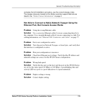
... from Lynx, and verify that the port on the host and the port on a port is configured as active. For cabling information, see the current release notes. Problem Wrong link speed. Not Able to Connect to a hub. Solution Verify that the interface is a good indication of a speed mismatch. An unblinking data and activity LED on the IP1200 Series are connecting to Nokia Network Voyager Using the Ethernet Port, But Console Access Works Problem Using the wrong Ethernet cable.
... from Lynx, and verify that the port on the host and the port on a port is configured as active. For cabling information, see the current release notes. Problem Wrong link speed. Not Able to Connect to a hub. Solution Verify that the interface is a good indication of a speed mismatch. An unblinking data and activity LED on the IP1200 Series are connecting to Nokia Network Voyager Using the Ethernet Port, But Console Access Works Problem Using the wrong Ethernet cable.
Installation Guide
Page 117
Solution Disconnect connections one at a time until the problem is localized to one computer and troubleshoot further. Be sure DIMMs click into place. Nokia IP1200 Series Security Platform Installation Guide 117 Make sure DIMMs are fully seated in adjacent slots J5/J6 and/or J7/J8. General Troubleshooting Information Problem High collision rate on the hub. Make sure DIMMs are not properly seated in DIMM sockets. Appliance Does Not Recognize New Memory Configuration Problem The DIMMs are seated in sockets. Solution Repeat memory installation procedures.
Solution Disconnect connections one at a time until the problem is localized to one computer and troubleshoot further. Be sure DIMMs click into place. Nokia IP1200 Series Security Platform Installation Guide 117 Make sure DIMMs are fully seated in adjacent slots J5/J6 and/or J7/J8. General Troubleshooting Information Problem High collision rate on the hub. Make sure DIMMs are not properly seated in DIMM sockets. Appliance Does Not Recognize New Memory Configuration Problem The DIMMs are seated in sockets. Solution Repeat memory installation procedures.

Installation Guide
Page 154
..., 82 connectors 77 expansion slots, PMC 24 F fan unit overview 35 fiber-optic cable 47, 80 field-replaceable units 119 four-port Ethernet 25 front panel 20, 23 G gasket 63 Gigabit Ethernet network interface cards connecting to 78 connectors 93, 96 grounding 55 H halt command 106 hard disk drive removing 123 hard disk drives overview 29 replacing 120 status LEDs 30 help command 106 hot swap button 121 Index - 154 Nokia IP1200 Series Security Platform Installation Guide
..., 82 connectors 77 expansion slots, PMC 24 F fan unit overview 35 fiber-optic cable 47, 80 field-replaceable units 119 four-port Ethernet 25 front panel 20, 23 G gasket 63 Gigabit Ethernet network interface cards connecting to 78 connectors 93, 96 grounding 55 H halt command 106 hard disk drive removing 123 hard disk drives overview 29 replacing 120 status LEDs 30 help command 106 hot swap button 121 Index - 154 Nokia IP1200 Series Security Platform Installation Guide

Installation Guide
Page 155
... I install command 107 installing network interface cards 61 IP-routing 21 IPSec 139 IPSO command-line interface 21 IPSO, booting 106 IPSO-SX 50 ISDN network interface cards cable pin assignments 87 connectors 86 L LC connector 47, 80 LEDs, system status 28 ls command 103 M management ports 24 managing the appliance 21 memory capacity 128 upgrading 128 monitoring the appliance 28 multicast traffic 21 N network interface cards dual-port 10/100 Ethernet 76, 79, 82 dual-port Gigabit Ethernet 78 installing 61 list of available 73 monitoring 71 removing 62 replacing 62 single-port...
... I install command 107 installing network interface cards 61 IP-routing 21 IPSec 139 IPSO command-line interface 21 IPSO, booting 106 IPSO-SX 50 ISDN network interface cards cable pin assignments 87 connectors 86 L LC connector 47, 80 LEDs, system status 28 ls command 103 M management ports 24 managing the appliance 21 memory capacity 128 upgrading 128 monitoring the appliance 28 multicast traffic 21 N network interface cards dual-port 10/100 Ethernet 76, 79, 82 dual-port Gigabit Ethernet 78 installing 61 list of available 73 monitoring 71 removing 62 replacing 62 single-port...


