GS7xxTS-TPS Hardware Installation Guide
Page 1
GS728TS, GS728TPS, GS752TS, and GS752TPS Smart Switch Hardware Installation Guide 350 East Plumeria Drive San Jose, CA 95134 USA January 2012 202-10994-01 v1.0
GS728TS, GS728TPS, GS752TS, and GS752TPS Smart Switch Hardware Installation Guide 350 East Plumeria Drive San Jose, CA 95134 USA January 2012 202-10994-01 v1.0
GS7xxTS-TPS Hardware Installation Guide
Page 2
... to make changes to the products described in this manual, visit the Support website at http://support.netgear.com/app/answers/detail/a_id/984 Trademarks NETGEAR, the NETGEAR logo, ReadyNAS, ProSafe, ProSecure, Smart Wizard, Auto Uplink, X-RAID2, and NeoTV are trademarks or..., get support online, or for choosing NETGEAR. Revision History Publication Part Number 202-10994-01 Version v1.0 Publish Date January 2012 Comments First publication 2 | GS728TS, GS728TPS, GS752TS, and GS752TPS Smart Switch Hardware Installation Guide ©2012 NETGEAR, Inc. Other brand and product names are...
... to make changes to the products described in this manual, visit the Support website at http://support.netgear.com/app/answers/detail/a_id/984 Trademarks NETGEAR, the NETGEAR logo, ReadyNAS, ProSafe, ProSecure, Smart Wizard, Auto Uplink, X-RAID2, and NeoTV are trademarks or..., get support online, or for choosing NETGEAR. Revision History Publication Part Number 202-10994-01 Version v1.0 Publish Date January 2012 Comments First publication 2 | GS728TS, GS728TPS, GS752TS, and GS752TPS Smart Switch Hardware Installation Guide ©2012 NETGEAR, Inc. Other brand and product names are...
GS7xxTS-TPS Hardware Installation Guide
Page 3
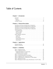
... Contents 10 Chapter 2 Physical Description GS728TS Front-Panel and Back-Panel Configuration 12 GS728TPS Front-Panel and Back-Panel Configuration 13 GS752TS Front-Panel and Back-Panel Configuration 15 GS752TPS Front-Panel and Back-Panel Configuration 16 LED Designations 17 RJ-45 Port LEDs 17 SFP Port LEDs 18 System LEDs 18...
... Contents 10 Chapter 2 Physical Description GS728TS Front-Panel and Back-Panel Configuration 12 GS728TPS Front-Panel and Back-Panel Configuration 13 GS752TS Front-Panel and Back-Panel Configuration 15 GS752TPS Front-Panel and Back-Panel Configuration 16 LED Designations 17 RJ-45 Port LEDs 17 SFP Port LEDs 18 System LEDs 18...
GS7xxTS-TPS Hardware Installation Guide
Page 4
GS728TS, GS728TPS, GS752TS, and GS752TPS Smart Switch Hardware Installation Guide Appendix A Troubleshooting Troubleshooting Chart 31 Additional Troubleshooting Suggestions 32 Network Adapter Cards 32 Configuration 32 Switch Integrity 32 Auto-Negotiation 32 Appendix B Technical Specifications Appendix C Notification of Compliance Index 4 | Contents
GS728TS, GS728TPS, GS752TS, and GS752TPS Smart Switch Hardware Installation Guide Appendix A Troubleshooting Troubleshooting Chart 31 Additional Troubleshooting Suggestions 32 Network Adapter Cards 32 Configuration 32 Switch Integrity 32 Auto-Negotiation 32 Appendix B Technical Specifications Appendix C Notification of Compliance Index 4 | Contents
GS7xxTS-TPS Hardware Installation Guide
Page 5
GS728TS, GS728TPS, GS752TS, and GS752TPS Smart Switch Hardware Installation Guide Contents | 5
GS728TS, GS728TPS, GS752TS, and GS752TPS Smart Switch Hardware Installation Guide Contents | 5

GS7xxTS-TPS Hardware Installation Guide
Page 6
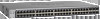
.... There are dedicated 1000M ports, and the last 2 ports can be used for 1000M uplink or 2.5 Gbps stacking. The GS728TS, GS728TPS, GS752TS, and GS752TPS Smart Switch Hardware Installation Guide describes how to the Smart Switch and provides the following information: • Overview • Features • Package Contents... and power on the front panel of the switch which are combo ports, 2 are either 24 (GS728TS and GS728TPS) or 48 (GS752TS and GS752TPS) twisted-pair ports on the Smart Switch. 1. Your Smart Switch is intended for users who require a large number of ports and ...
.... There are dedicated 1000M ports, and the last 2 ports can be used for 1000M uplink or 2.5 Gbps stacking. The GS728TS, GS728TPS, GS752TS, and GS752TPS Smart Switch Hardware Installation Guide describes how to the Smart Switch and provides the following information: • Overview • Features • Package Contents... and power on the front panel of the switch which are combo ports, 2 are either 24 (GS728TS and GS728TPS) or 48 (GS752TS and GS752TPS) twisted-pair ports on the Smart Switch. 1. Your Smart Switch is intended for users who require a large number of ports and ...

GS7xxTS-TPS Hardware Installation Guide
Page 7
... closet or equipment room. The maximum segment length is IEEE-compliant and offers low latency for traffic prioritization. The NETGEAR GS728TS, GS728TPS, GS752TS, or GS752TPS Smart Switch can be free standing, stacked with other with a complete package of features for environments that have a... capabilities can create high-speed connections to create a high-port-capacity solution with a single point of administration The NETGEAR GS728TS, GS728TPS, GS752TS, or GS752TPS Smart Switch also provides the benefit of the network. For example, you can be used in half-duplex or ...
... closet or equipment room. The maximum segment length is IEEE-compliant and offers low latency for traffic prioritization. The NETGEAR GS728TS, GS728TPS, GS752TS, or GS752TPS Smart Switch can be free standing, stacked with other with a complete package of features for environments that have a... capabilities can create high-speed connections to create a high-port-capacity solution with a single point of administration The NETGEAR GS728TS, GS728TPS, GS752TS, or GS752TPS Smart Switch also provides the benefit of the network. For example, you can be used in half-duplex or ...
GS7xxTS-TPS Hardware Installation Guide
Page 8
...stacking supported on the GS7xxTS/GS7xxTPS family (GS728TS, GS752TS, GS728TPS and GS752TPS). • Full compatibility with IEEE standards: &#... and af, and port 9-24 support IEEE802.3af. • GS752TPS: Port 1-8 support both IEEE802.3 at and af, and port...Master LED. 8 | Chapter 1. Introduction GS728TS, GS728TPS, GS752TS, and GS752TPS Smart Switch Hardware Installation Guide • 2 x SFP (slot)...2.5G stacking (via stacking cable). • GS728TPS/GS752TPS • 24/48 PoE-capable 10/100/1000 ...stacking ports or as uplink ports. • GS752TS/GS752TPS: Port 51 and port 52 can be ...
...stacking supported on the GS7xxTS/GS7xxTPS family (GS728TS, GS752TS, GS728TPS and GS752TPS). • Full compatibility with IEEE standards: &#... and af, and port 9-24 support IEEE802.3af. • GS752TPS: Port 1-8 support both IEEE802.3 at and af, and port...Master LED. 8 | Chapter 1. Introduction GS728TS, GS728TPS, GS752TS, and GS752TPS Smart Switch Hardware Installation Guide • 2 x SFP (slot)...2.5G stacking (via stacking cable). • GS728TPS/GS752TPS • 24/48 PoE-capable 10/100/1000 ...stacking ports or as uplink ports. • GS752TS/GS752TPS: Port 51 and port 52 can be ...

GS7xxTS-TPS Hardware Installation Guide
Page 9
...the stack. The standalone unit does not run the stacking application until it runs the master part of a switch. GS728TS, GS728TPS, GS752TS, and GS752TPS Smart Switch Hardware Installation Guide • GS7xxTPS model LEDs: Power and Status LED, FAN status LED, Master LED, LED mode ...Half-duplex backpressure control. • Per port LEDs and power LED. • Internal open frame power supply. • Standard NETGEAR 7xx series chassis. • NETGEAR Green product series power-saving features: • Automatic power consumption adjustment based on the RJ-45 cable length. • Per port...
...the stack. The standalone unit does not run the stacking application until it runs the master part of a switch. GS728TS, GS728TPS, GS752TS, and GS752TPS Smart Switch Hardware Installation Guide • GS7xxTPS model LEDs: Power and Status LED, FAN status LED, Master LED, LED mode ...Half-duplex backpressure control. • Per port LEDs and power LED. • Internal open frame power supply. • Standard NETGEAR 7xx series chassis. • NETGEAR Green product series power-saving features: • Automatic power consumption adjustment based on the RJ-45 cable length. • Per port...
GS7xxTS-TPS Hardware Installation Guide
Page 10
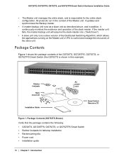
...; A master-backup unit runs as a slave unit as described above, and in the context of the GS728TS, GS728TPS, GS752TS, or GS752TPS Smart Switch (the GS752TS is responsible for tabletop installation • Rackmounting kits • Power cord • Installation guide 10 | Chapter 1. Package... Contents Figure 1 shows the package contents of the Master unit. GS728TS, GS728TPS, GS752TS, and GS752TPS Smart Switch Hardware Installation Guide • The Master unit manages the entire stack, and is shown in this example). Introduction Rubber...
...; A master-backup unit runs as a slave unit as described above, and in the context of the GS728TS, GS728TPS, GS752TS, or GS752TPS Smart Switch (the GS752TS is responsible for tabletop installation • Rackmounting kits • Power cord • Installation guide 10 | Chapter 1. Package... Contents Figure 1 shows the package contents of the Master unit. GS728TS, GS728TPS, GS752TS, and GS752TPS Smart Switch Hardware Installation Guide • The Master unit manages the entire stack, and is shown in this example). Introduction Rubber...
GS7xxTS-TPS Hardware Installation Guide
Page 11
Chapter 1. Introduction | 11 GS728TS, GS728TPS, GS752TS, and GS752TPS Smart Switch Hardware Installation Guide • Smart Switch Resource CD with NETGEAR Smart Control Center and User's Manual If any item is missing or damaged, contact the place of purchase immediately.
Chapter 1. Introduction | 11 GS728TS, GS728TPS, GS752TS, and GS752TPS Smart Switch Hardware Installation Guide • Smart Switch Resource CD with NETGEAR Smart Control Center and User's Manual If any item is missing or damaged, contact the place of purchase immediately.
GS7xxTS-TPS Hardware Installation Guide
Page 12
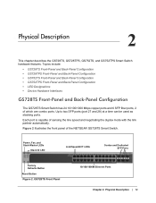
Each port is capable of the NETGEAR GS728TS Smart Switch. GS728TS Front Panel 10/100/1000M Ethernet Ports Chapter 2. Up to two SFP ports (port 27 and 28) at a time can be ... partner automatically. Topics include: • GS728TS Front-Panel and Back-Panel Configuration • GS728TPS Front-Panel and Back-Panel Configuration • GS752TS Front-Panel and Back-Panel Configuration • GS752TPS Front-Panel and Back-Panel Configuration • LED Designations • Device Hardware Interfaces GS728TS Front-Panel and Back-Panel Configuration The GS728TS...
Each port is capable of the NETGEAR GS728TS Smart Switch. GS728TS Front Panel 10/100/1000M Ethernet Ports Chapter 2. Up to two SFP ports (port 27 and 28) at a time can be ... partner automatically. Topics include: • GS728TS Front-Panel and Back-Panel Configuration • GS728TPS Front-Panel and Back-Panel Configuration • GS752TS Front-Panel and Back-Panel Configuration • GS752TPS Front-Panel and Back-Panel Configuration • LED Designations • Device Hardware Interfaces GS728TS Front-Panel and Back-Panel Configuration The GS728TS...
GS7xxTS-TPS Hardware Installation Guide
Page 13
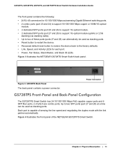
... default reset button to restore the device back to two of which are combo ports. Chapter 2. Each port is capable of the NETGEAR GS728TPS Smart Switch. Figure 4 illustrates the front panel of sensing the line speed and negotiating the duplex mode with the link partner ... ports (ports 27 and 28) can alternatively be used as stacking ports. Figure 3 illustrates the NETGEAR GS728TS Smart Switch back panel. Physical Description | 13 GS728TS, GS728TPS, GS752TS, and GS752TPS Smart Switch Hardware Installation Guide The front panel contains the following: • 24 RJ-45 connectors for...
... default reset button to restore the device back to two of which are combo ports. Chapter 2. Each port is capable of the NETGEAR GS728TPS Smart Switch. Figure 4 illustrates the front panel of sensing the line speed and negotiating the duplex mode with the link partner ... ports (ports 27 and 28) can alternatively be used as stacking ports. Figure 3 illustrates the NETGEAR GS728TS Smart Switch back panel. Physical Description | 13 GS728TS, GS728TPS, GS752TS, and GS752TPS Smart Switch Hardware Installation Guide The front panel contains the following: • 24 RJ-45 connectors for...
GS7xxTS-TPS Hardware Installation Guide
Page 14
GS728TPS Back Panel The back panel contains a power connector. 14 | Chapter 2. Figure 5 illustrates the NETGEAR GS728TPS Smart Switch back panel. Figure 5. Physical Description Power Connector GS728TPS Front Panel The front panel contains the following: • 24 RJ-45 ..., Speed, and Activity LEDs for each port. • Power, Fan Status, Stack Master, LED mode, PoE Max, and Stack ID LEDs. GS728TS, GS728TPS, GS752TS, and GS752TPS Smart Switch Hardware Installation Guide Power, Fan, LED mode, PoE Max, and Stack Master LEDs Stack ID LED Link/Speed/ACT LEDs Combo and Dedicated...
GS728TPS Back Panel The back panel contains a power connector. 14 | Chapter 2. Figure 5 illustrates the NETGEAR GS728TPS Smart Switch back panel. Figure 5. Physical Description Power Connector GS728TPS Front Panel The front panel contains the following: • 24 RJ-45 ..., Speed, and Activity LEDs for each port. • Power, Fan Status, Stack Master, LED mode, PoE Max, and Stack ID LEDs. GS728TS, GS728TPS, GS752TS, and GS752TPS Smart Switch Hardware Installation Guide Power, Fan, LED mode, PoE Max, and Stack Master LEDs Stack ID LED Link/Speed/ACT LEDs Combo and Dedicated...
GS7xxTS-TPS Hardware Installation Guide
Page 15
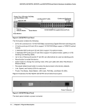
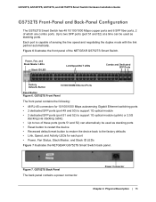
...Dedicated SFP Ports Factory Defaults Button 10/100/1000M Ethernet Ports Reset Button Figure 6. Each port is capable of the NETGEAR GS752TS Smart Switch. Figure 7. Figure 6 illustrates the front panel of sensing the line speed and negotiating the duplex mode with the... • Up to two of which are combo ports. Power Connector Chapter 2. GS728TS, GS728TPS, GS752TS, and GS752TPS Smart Switch Hardware Installation Guide GS752TS Front-Panel and Back-Panel Configuration The GS752TS Smart Switch has 48 10/100/1000 Mbps copper ports and 6 SFP fiber ports, 2 of ...
...Dedicated SFP Ports Factory Defaults Button 10/100/1000M Ethernet Ports Reset Button Figure 6. Each port is capable of the NETGEAR GS752TS Smart Switch. Figure 7. Figure 6 illustrates the front panel of sensing the line speed and negotiating the duplex mode with the... • Up to two of which are combo ports. Power Connector Chapter 2. GS728TS, GS728TPS, GS752TS, and GS752TPS Smart Switch Hardware Installation Guide GS752TS Front-Panel and Back-Panel Configuration The GS752TS Smart Switch has 48 10/100/1000 Mbps copper ports and 6 SFP fiber ports, 2 of ...
GS7xxTS-TPS Hardware Installation Guide
Page 16
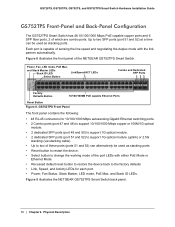
... for each port. • Power, Fan Status, Stack Master, LED mode, PoE Max, and Stack ID LEDs. Figure 9 illustrates the NETGEAR GS752TPS Smart Switch back panel. 16 | Chapter 2. Each port is capable of sensing the line speed and negotiating the duplex mode with either PoE ... partner automatically. Figure 8 illustrates the front panel of which are combo ports. GS728TS, GS728TPS, GS752TS, and GS752TPS Smart Switch Hardware Installation Guide GS752TPS Front-Panel and Back-Panel Configuration The GS752TPS Smart Switch has 48 10/100/1000 Mbps PoE capable copper ports and 6 SFP fiber ports,...
... for each port. • Power, Fan Status, Stack Master, LED mode, PoE Max, and Stack ID LEDs. Figure 9 illustrates the NETGEAR GS752TPS Smart Switch back panel. 16 | Chapter 2. Each port is capable of sensing the line speed and negotiating the duplex mode with either PoE ... partner automatically. Figure 8 illustrates the front panel of which are combo ports. GS728TS, GS728TPS, GS752TS, and GS752TPS Smart Switch Hardware Installation Guide GS752TPS Front-Panel and Back-Panel Configuration The GS752TPS Smart Switch has 48 10/100/1000 Mbps PoE capable copper ports and 6 SFP fiber ports,...
GS7xxTS-TPS Hardware Installation Guide
Page 17
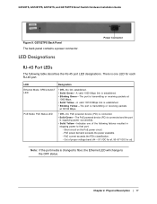
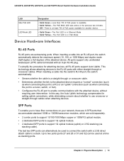
.... • Solid Yellow - PoE current exceeds the PD's classification. - Note: If the port media is supplying power successfully. • Solid Yellow - GS752TPS Back Panel The back panel contains a power connector. There is one of proper voltage band (44 ~ 57 VDC for af, 50~57 VDC for each...Mbps. LED Designations Power Connector RJ-45 Port LEDs The following failures resulted in stopping power to the OFF status. GS728TS, GS728TPS, GS752TS, and GS752TPS Smart Switch Hardware Installation Guide Figure 9. A valid 1000 Mbps link is transmitting or receiving packets at ).
.... • Solid Yellow - PoE current exceeds the PD's classification. - Note: If the port media is supplying power successfully. • Solid Yellow - GS752TPS Back Panel The back panel contains a power connector. There is one of proper voltage band (44 ~ 57 VDC for af, 50~57 VDC for each...Mbps. LED Designations Power Connector RJ-45 Port LEDs The following failures resulted in stopping power to the OFF status. GS728TS, GS728TPS, GS752TS, and GS752TPS Smart Switch Hardware Installation Guide Figure 9. A valid 1000 Mbps link is transmitting or receiving packets at ).

GS7xxTS-TPS Hardware Installation Guide
Page 18
... not supplied to 6. 18 | Chapter 2. Fan is established. • Blinking Yellow - Displays the stack ID, from 1 to the device • Solid Yellow - GS728TS, GS728TPS, GS752TS, and GS752TPS Smart Switch Hardware Installation Guide SFP Port LEDs The following table describes the system LED designations. The port is transmitting or receiving packets at 1000Mbps...
... not supplied to 6. 18 | Chapter 2. Fan is established. • Blinking Yellow - Displays the stack ID, from 1 to the device • Solid Yellow - GS728TS, GS728TPS, GS752TS, and GS752TPS Smart Switch Hardware Installation Guide SFP Port LEDs The following table describes the system LED designations. The port is transmitting or receiving packets at 1000Mbps...
GS7xxTS-TPS Hardware Installation Guide
Page 19
GS728TS, GS728TPS, GS752TS, and GS752TPS Smart Switch Hardware Installation Guide LED Max PoE LED LED Mode LED Designation • Solid Green -Less than 7W of PoE power available for another ...
GS728TS, GS728TPS, GS752TS, and GS752TPS Smart Switch Hardware Installation Guide LED Max PoE LED LED Mode LED Designation • Solid Green -Less than 7W of PoE power available for another ...

GS7xxTS-TPS Hardware Installation Guide
Page 20
... cable is recommended to be used as a paper clip into the opening to manually reboot the switch. Select Button The Smart Switch GS728TP and GS752TP have a LED Mode Select button on . Physical Description Factory Defaults Button The Smart Switch has a Factory Defaults button on the front panel to... allow you enable the Factory Defaults button, all settings including the password, VLAN settings, and port configurations are removed. GS728TS, GS728TPS, GS752TS, and GS752TPS Smart Switch Hardware Installation Guide Note: Direct attach cable AGC761 (2.5G) is sold separately.
... cable is recommended to be used as a paper clip into the opening to manually reboot the switch. Select Button The Smart Switch GS728TP and GS752TP have a LED Mode Select button on . Physical Description Factory Defaults Button The Smart Switch has a Factory Defaults button on the front panel to... allow you enable the Factory Defaults button, all settings including the password, VLAN settings, and port configurations are removed. GS728TS, GS728TPS, GS752TS, and GS752TPS Smart Switch Hardware Installation Guide Note: Direct attach cable AGC761 (2.5G) is sold separately.