FSM726v3 Hardware Installation Guide
Page 2
..., the user may , however, be required to test the series for Telecommunications Approvals has been notified of the placing of this equipment on the standard of the product(s) or circuit layout(s) described herein. NETGEAR, INC. Information is subject to the products described in this equipment is hereby certified that the NETGEAR ProSafe 24-Port Ethernet L2 Managed Switch Model FSM726 has...
..., the user may , however, be required to test the series for Telecommunications Approvals has been notified of the placing of this equipment on the standard of the product(s) or circuit layout(s) described herein. NETGEAR, INC. Information is subject to the products described in this equipment is hereby certified that the NETGEAR ProSafe 24-Port Ethernet L2 Managed Switch Model FSM726 has...
FSM726v3 Hardware Installation Guide
Page 3
... the user may cause harmful interference to take appropriate measures. Customer Support Refer to certify that may cause undesired operation. EN 55 022 Declaration of Conformance This is to the Support Information Card that interference will not occur in a particular installation. • This device must accept any interference received, including interference that the NETGEAR ProSafe 24-Port Ethernet L2 Managed Switch Model FSM726 is...
... the user may cause harmful interference to take appropriate measures. Customer Support Refer to certify that may cause undesired operation. EN 55 022 Declaration of Conformance This is to the Support Information Card that interference will not occur in a particular installation. • This device must accept any interference received, including interference that the NETGEAR ProSafe 24-Port Ethernet L2 Managed Switch Model FSM726 is...

FSM726v3 Hardware Installation Guide
Page 5
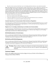
... manual is used to install, configure and troubleshoot the ProSafe 24Port Ethernet L2 Managed Switch Model FSM726. Tip: This format is intended for readers with 2 Gigabit Ethernet Ports FSM726 Hardware Installation Guide describes how to highlight information of note might result in a malfunction or damage to highlight a procedure that will save time or resources. The information in the following typographical conventions: Italic Bold italic Emphasis, books, CDs, file and server...
... manual is used to install, configure and troubleshoot the ProSafe 24Port Ethernet L2 Managed Switch Model FSM726. Tip: This format is intended for readers with 2 Gigabit Ethernet Ports FSM726 Hardware Installation Guide describes how to highlight information of note might result in a malfunction or damage to highlight a procedure that will save time or resources. The information in the following typographical conventions: Italic Bold italic Emphasis, books, CDs, file and server...
FSM726v3 Hardware Installation Guide
Page 6
.... - Managed Layer 2 Switch with 2 Gigabit Ethernet Ports FSM726 Hardware Installation Guide • Scope. This manual is available on the Adobe Web site at the top left corner of any page. • Click the PDF of any page in the chapter you can choose one of any page. • Click the Complete PDF Manual link at http://kbserver.netgear.com. The PDF version of the chapter you were viewing opens in...
.... - Managed Layer 2 Switch with 2 Gigabit Ethernet Ports FSM726 Hardware Installation Guide • Scope. This manual is available on the Adobe Web site at the top left corner of any page. • Click the PDF of any page in the chapter you can choose one of any page. • Click the Complete PDF Manual link at http://kbserver.netgear.com. The PDF version of the chapter you were viewing opens in...

FSM726v3 Hardware Installation Guide
Page 10
Managed Layer 2 Switch with 2 Gigabit Ethernet Ports FSM726 Hardware Installation Guide Appendix A Factory Default Settings and Technical Specifications Factory Default Settings A-1 Technical Specifications A-2 x v1.0, July 2009
Managed Layer 2 Switch with 2 Gigabit Ethernet Ports FSM726 Hardware Installation Guide Appendix A Factory Default Settings and Technical Specifications Factory Default Settings A-1 Technical Specifications A-2 x v1.0, July 2009
FSM726v3 Hardware Installation Guide
Page 11
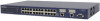
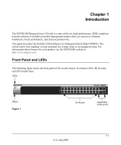
... at http://www.netgear.com. It includes powerful management features that you can be free-standing, or rack-mounted in a wiring closet or an equipment room. This guide describes the ProSafe 24-Port Ethernet L2 Managed Switch Model FSM726. It contains LEDs, RJ-45 jacks, and SFP module bays. LEDs Reset Figure 1 RJ-45 jacks copper/fiber combo ports 1-1 v1.0, July 2009 Chapter 1 Introduction The NETGEAR Managed Layer 2 Switch is a state-of the switch chassis.
... at http://www.netgear.com. It includes powerful management features that you can be free-standing, or rack-mounted in a wiring closet or an equipment room. This guide describes the ProSafe 24-Port Ethernet L2 Managed Switch Model FSM726. It contains LEDs, RJ-45 jacks, and SFP module bays. LEDs Reset Figure 1 RJ-45 jacks copper/fiber combo ports 1-1 v1.0, July 2009 Chapter 1 Introduction The NETGEAR Managed Layer 2 Switch is a state-of the switch chassis.

FSM726v3 Hardware Installation Guide
Page 12
... fiber, the copper LEDs changes to Off status. 1-2 Introduction v1.0, July 2009 A valid 1000 Mbps link is established on the port. • Blinking green. POST, CPU, or power supply has failed • Off. A valid 1000 Mbps SFP module link is established on the port. • Blinking Yellow. Link/ACT LED • Off. A valid 10/00Mbps link is sending or receiving packets at 1000 Mbps. • Solid Yellow. Managed Layer 2 Switch with 2 Gigabit Ethernet Ports FSM726 Hardware Installation Guide...
... fiber, the copper LEDs changes to Off status. 1-2 Introduction v1.0, July 2009 A valid 1000 Mbps link is established on the port. • Blinking green. POST, CPU, or power supply has failed • Off. A valid 1000 Mbps SFP module link is established on the port. • Blinking Yellow. Link/ACT LED • Off. A valid 10/00Mbps link is sending or receiving packets at 1000 Mbps. • Solid Yellow. Managed Layer 2 Switch with 2 Gigabit Ethernet Ports FSM726 Hardware Installation Guide...
FSM726v3 Hardware Installation Guide
Page 13
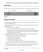
... in a wet environment. The power cable, extension cable, or plug is damaged. - Also, do not block cooling vents. • Do not spill food or liquids on your trained service provider. Opening or removing covers that are marked with the triangular symbol with 2 Gigabit Ethernet Ports FSM726 Hardware Installation Guide Rear Panel The rear panel has a console port and a standard AC power receptacle for the supplied power cord. An object has fallen...
... in a wet environment. The power cable, extension cable, or plug is damaged. - Also, do not block cooling vents. • Do not spill food or liquids on your trained service provider. Opening or removing covers that are marked with the triangular symbol with 2 Gigabit Ethernet Ports FSM726 Hardware Installation Guide Rear Panel The rear panel has a console port and a standard AC power receptacle for the supplied power cord. An object has fallen...

FSM726v3 Hardware Installation Guide
Page 14
... power, use adapter plugs or remove the grounding prong from the type of power source required, consult your service provider or local power company. • To help protect your system. route cables so that the voltage selection switch (if provided) on the power supply ...rated for the product and for use a three-wire cable with approved equipment. • Allow the product to operate with 2 Gigabit Ethernet Ports FSM726 Hardware Installation Guide • Do not push any cables. 1-4 Introduction v1.0, July 2009 If you are electrically rated to cool before removing...
... power, use adapter plugs or remove the grounding prong from the type of power source required, consult your service provider or local power company. • To help protect your system. route cables so that the voltage selection switch (if provided) on the power supply ...rated for the product and for use a three-wire cable with approved equipment. • Allow the product to operate with 2 Gigabit Ethernet Ports FSM726 Hardware Installation Guide • Do not push any cables. 1-4 Introduction v1.0, July 2009 If you are electrically rated to cool before removing...

FSM726v3 Hardware Installation Guide
Page 17
The package contains the following items: • Managed Layer 2 Switch with preinstalled software • Power adapter cord • Rubber footpads for the Managed Layer 2 Fast Ethernet Switch model FSM726. Documentation including the Command Line Interface Reference for the ProSafe 7200 Series Layer-2 Switches, the Administration Manual for the 7200 Series Layer-2 Switches, and this Hardware Installation Guide • Warranty and Support Card If you ordered SFP modules with your place of purchase immediately. 2-1 v1.0, July 2009 If any...
The package contains the following items: • Managed Layer 2 Switch with preinstalled software • Power adapter cord • Rubber footpads for the Managed Layer 2 Fast Ethernet Switch model FSM726. Documentation including the Command Line Interface Reference for the ProSafe 7200 Series Layer-2 Switches, the Administration Manual for the 7200 Series Layer-2 Switches, and this Hardware Installation Guide • Warranty and Support Card If you ordered SFP modules with your place of purchase immediately. 2-1 v1.0, July 2009 If any...

FSM726v3 Hardware Installation Guide
Page 19
... lets you access the front panel RJ-45 ports, view the front panel LEDs, and access the rear-panel power connector. Provide a power source within 6 feet (1.8 meters) of the switch. The ambient switch operating temperature range is grounded and physically secure. Keep at least 2 inches (5.08 centimeters) free on page 2-5. Managed Layer 2 Switch with 2 Gigabit Ethernet Ports FSM726 Hardware Installation Guide Installation Install the equipment in the following site requirements. Apply power, and check the LEDs. Use the rack mounting kit supplied with a maximum...
... lets you access the front panel RJ-45 ports, view the front panel LEDs, and access the rear-panel power connector. Provide a power source within 6 feet (1.8 meters) of the switch. The ambient switch operating temperature range is grounded and physically secure. Keep at least 2 inches (5.08 centimeters) free on page 2-5. Managed Layer 2 Switch with 2 Gigabit Ethernet Ports FSM726 Hardware Installation Guide Installation Install the equipment in the following site requirements. Apply power, and check the LEDs. Use the rack mounting kit supplied with a maximum...

FSM726v3 Hardware Installation Guide
Page 21
... POST fails, the Power LED blinks yellow. Hardware Installation 2-5 v1.0, July 2009 Tighten the screws with a No. 1 Phillips screwdriver to secure each bracket and to the rack. 5. Check the Power LED on self-test (POST). • If the switch passes the test, the LED turns green and the switch is not controlled by a wall switch (which can turn off power to the switch). Align the bracket and rack holes. Use two pan-head screws with 2 Gigabit Ethernet Ports FSM726 Hardware Installation Guide...
... POST fails, the Power LED blinks yellow. Hardware Installation 2-5 v1.0, July 2009 Tighten the screws with a No. 1 Phillips screwdriver to secure each bracket and to the rack. 5. Check the Power LED on self-test (POST). • If the switch passes the test, the LED turns green and the switch is not controlled by a wall switch (which can turn off power to the switch). Align the bracket and rack holes. Use two pan-head screws with 2 Gigabit Ethernet Ports FSM726 Hardware Installation Guide...
FSM726v3 Hardware Installation Guide
Page 23
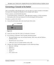
... comes with the Windows operating systems. • Macintosh users can use ZTerm. • UNIX users can use the Command Line Interface (CLI) to identify the IP address. Connect the null-modem cable to it with a terminal or workstation. Managed Layer 2 Switch with 2 Gigabit Ethernet Ports FSM726 Hardware Installation Guide Connecting a Console to the Switch After you install the switch and apply power, you can use a terminal emulator such as TIP. 4. You can connect to the console port of the cable to the switch: 1. Console port Figure 2-3 2.
... comes with the Windows operating systems. • Macintosh users can use ZTerm. • UNIX users can use the Command Line Interface (CLI) to identify the IP address. Connect the null-modem cable to it with a terminal or workstation. Managed Layer 2 Switch with 2 Gigabit Ethernet Ports FSM726 Hardware Installation Guide Connecting a Console to the Switch After you install the switch and apply power, you can use a terminal emulator such as TIP. 4. You can connect to the console port of the cable to the switch: 1. Console port Figure 2-3 2.

FSM726v3 Hardware Installation Guide
Page 24
The following documents are provided for this purpose: • Command Line Interface Reference for the ProSafe 7200 Series Layer-2 Switches: Gives detailed examples of how to configure the switch. Managed Layer 2 Switch with 2 Gigabit Ethernet Ports FSM726 Hardware Installation Guide After you connect a console to the switch, you will need to use the CLI, and is located on the Resource CD. • Administration Manual for the 7200 Series Layer-2 Switches: Describes configuration tasks, and is located on the Resource CD. 2-8 Hardware Installation v1.0, July 2009
The following documents are provided for this purpose: • Command Line Interface Reference for the ProSafe 7200 Series Layer-2 Switches: Gives detailed examples of how to configure the switch. Managed Layer 2 Switch with 2 Gigabit Ethernet Ports FSM726 Hardware Installation Guide After you connect a console to the switch, you will need to use the CLI, and is located on the Resource CD. • Administration Manual for the 7200 Series Layer-2 Switches: Describes configuration tasks, and is located on the Resource CD. 2-8 Hardware Installation v1.0, July 2009

FSM726v3 Hardware Installation Guide
Page 25
... received Link LED is off or intermittent. problem. device are not Verify that the attached device is set performance degradation is slow or Half- Chapter 3 Troubleshooting Troubleshooting Chart The table below lists symptoms, causes, and solutions of the network. See Appendix A, "Factory Default Settings and Technical Specifications. • Check for the switch at the switch and at both the switch and the connecting device. • Make sure that all cables used are functioning. File...
... received Link LED is off or intermittent. problem. device are not Verify that the attached device is set performance degradation is slow or Half- Chapter 3 Troubleshooting Troubleshooting Chart The table below lists symptoms, causes, and solutions of the network. See Appendix A, "Factory Default Settings and Technical Specifications. • Check for the switch at the switch and at both the switch and the connecting device. • Make sure that all cables used are functioning. File...
FSM726v3 Hardware Installation Guide
Page 26
...duplex mode defaults to the troubleshooting suggestions in this section. • Network Adapter Cards Make sure that shipped with 2 Gigabit Ethernet Ports FSM726 Hardware Installation Guide Additional Troubleshooting Suggestions If the suggestions in working condition and the software driver has been installed. • Configuration If problems occur after you change the network configuration, restore the original connections. To reset the switch, use the Tools> Reset command or remove AC power from the switch and then reapply AC power. Managed Layer 2 Switch with your problem, refer to...
...duplex mode defaults to the troubleshooting suggestions in this section. • Network Adapter Cards Make sure that shipped with 2 Gigabit Ethernet Ports FSM726 Hardware Installation Guide Additional Troubleshooting Suggestions If the suggestions in working condition and the software driver has been installed. • Configuration If problems occur after you change the network configuration, restore the original connections. To reset the switch, use the Tools> Reset command or remove AC power from the switch and then reapply AC power. Managed Layer 2 Switch with your problem, refer to...
FSM726v3 Hardware Installation Guide
Page 27
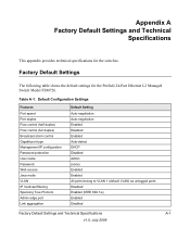
...Default Configuration Settings Features Port speed Port duplex Flow control (half duplex) Flow control (full duplex) Broadcast storm control Gigabit port type Management IP configuration Password protection User name Password Web access Java mode VLAN IP multicast filtering Spanning Tree Protocol Admin edge port Link aggregation Default Setting Auto-negotiation Auto-negotiation Enabled Disabled Enabled Auto-detect DHCP Disabled Admin (none) Enabled Enabled All ports belong to VLAN 1 (default VLAN) as untagged ports Disabled Enabled (IEEE 802.1w) Enabled Disabled Factory Default Settings...
...Default Configuration Settings Features Port speed Port duplex Flow control (half duplex) Flow control (full duplex) Broadcast storm control Gigabit port type Management IP configuration Password protection User name Password Web access Java mode VLAN IP multicast filtering Spanning Tree Protocol Admin edge port Link aggregation Default Setting Auto-negotiation Auto-negotiation Enabled Disabled Enabled Auto-detect DHCP Disabled Admin (none) Enabled Enabled All ports belong to VLAN 1 (default VLAN) as untagged ports Disabled Enabled (IEEE 802.1w) Enabled Disabled Factory Default Settings...
FSM726v3 Hardware Installation Guide
Page 28
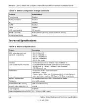
... FSM726 Hardware Installation Guide Table A-1. Mean time between failure (MTBF) 562,110 hours (~ 64.2 years) A-2 Factory Default Settings and Technical Specifications v1.0, July 2009 Default Configuration Settings (continued) Features Port mirroring Traffic prioritization ACL GVRP GMRP MAC address aging SNMP community VLAN Ingress filtering Default Setting Disabled Disabled Disabled Disabled Disabled 300 seconds Public (read-only access), private (read/write access) Enabled Technical Specifications Table A-2. Technical Specifications Feature Description IEEE network protocol...
... FSM726 Hardware Installation Guide Table A-1. Mean time between failure (MTBF) 562,110 hours (~ 64.2 years) A-2 Factory Default Settings and Technical Specifications v1.0, July 2009 Default Configuration Settings (continued) Features Port mirroring Traffic prioritization ACL GVRP GMRP MAC address aging SNMP community VLAN Ingress filtering Default Setting Disabled Disabled Disabled Disabled Disabled 300 seconds Public (read-only access), private (read/write access) Enabled Technical Specifications Table A-2. Technical Specifications Feature Description IEEE network protocol...
FSM726v3 Hardware Installation Guide
Page 29
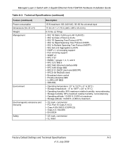
... Spanning Tree Protocol (RSTP) • 802.1s Multiple Spanning Tree Protocol (MSTP) • 802.3ad Link Aggregation (LACP) • IGMP v1, v2 snooping support • Port mirroring support • SNMP v3 • RFC1757 • RMON 1 groups 1, 2, 3, and 9 • RFC1213 MIB II • RFC1643 Ethernet interface MIB • RFC1493 bridge MIB • RFC2131 DHCP client (and BOOTP) • RFC2138 RADIUS client • Broadcast storm control • Private...
... Spanning Tree Protocol (RSTP) • 802.1s Multiple Spanning Tree Protocol (MSTP) • 802.3ad Link Aggregation (LACP) • IGMP v1, v2 snooping support • Port mirroring support • SNMP v3 • RFC1757 • RMON 1 groups 1, 2, 3, and 9 • RFC1213 MIB II • RFC1643 Ethernet interface MIB • RFC1493 bridge MIB • RFC2131 DHCP client (and BOOTP) • RFC2138 RADIUS client • Broadcast storm control • Private...

FSM726v3 Hardware Installation Guide
Page 30
Managed Layer 2 Switch with 2 Gigabit Ethernet Ports FSM726 Hardware Installation Guide A-4 Factory Default Settings and Technical Specifications v1.0, July 2009
Managed Layer 2 Switch with 2 Gigabit Ethernet Ports FSM726 Hardware Installation Guide A-4 Factory Default Settings and Technical Specifications v1.0, July 2009


