
FS750 Reference Manual
Page 2
... that the NETGEAR Model FS726 Modular Fast Ethernet Switch and Model FS750 Modular Fast Ethernet Switch have been suppressed in accordance with the regulations. Certificate of the Manufacturer/Importer It is in the first category (information equipment to be caused to equipment such as radios and TV receivers. Voluntary Control Council for example, test transmitters) in the operating instructions. ii The...
... that the NETGEAR Model FS726 Modular Fast Ethernet Switch and Model FS750 Modular Fast Ethernet Switch have been suppressed in accordance with the regulations. Certificate of the Manufacturer/Importer It is in the first category (information equipment to be caused to equipment such as radios and TV receivers. Voluntary Control Council for example, test transmitters) in the operating instructions. ii The...

FS750 Reference Manual
Page 3
... of EN 55024 Class A (CISPR 22). ! However, there is no guarantee that the NETGEAR Model FS726 Modular Fast Ethernet Switch and Model FS750 Modular Fast Ethernet Switch are shielded against the generation of radio interference in accordance with the instructions, may be determined by turning the equipment off and on a circuit different from digital apparatus as set out in a particular installation.
... of EN 55024 Class A (CISPR 22). ! However, there is no guarantee that the NETGEAR Model FS726 Modular Fast Ethernet Switch and Model FS750 Modular Fast Ethernet Switch are shielded against the generation of radio interference in accordance with the instructions, may be determined by turning the equipment off and on a circuit different from digital apparatus as set out in a particular installation.

FS750 Reference Manual
Page 4
... your point-of-purchase representative. A direct connection to your switch. • E-mail Technical Support at support@NETGEAR.com. iv Our technicians are standing by to assist you 24 hours a day, 7 days a week.If you can be returned to the Internet and a Web browser such as Internet Explorer or Netscape are outside North America, please refer to the phone numbers listed on the Support Information Card...
... your point-of-purchase representative. A direct connection to your switch. • E-mail Technical Support at support@NETGEAR.com. iv Our technicians are standing by to assist you 24 hours a day, 7 days a week.If you can be returned to the Internet and a Web browser such as Internet Explorer or Netscape are outside North America, please refer to the phone numbers listed on the Support Information Card...

FS750 Reference Manual
Page 5
...Front and Back Panels 2-1 10/100 Mbps RJ-45 Ports 2-3 LED Mode Button and LED Descriptions 2-4 Module Bays 2-5 Auto Uplink 2-5 Reset Button 2-7 CHAPTER 3 Applications 3-1 Desktop Switching 3-1 Segment Switching and Bridging from 10 Mbps to 100 Mbps 3-2 Media Compatibility and Conversion 3-2 CHAPTER 4 Installation 4-1 Preparing the Site 4-2 Installing the Switch 4-3 Installing the Switch on a Flat Surface 4-3 Installing the Switch in a Rack 4-3 Connecting Devices to the Switch 4-4 Using Gigabit Ethernet Modules 4-5 Checking the Installation 4-6 Applying AC...
...Front and Back Panels 2-1 10/100 Mbps RJ-45 Ports 2-3 LED Mode Button and LED Descriptions 2-4 Module Bays 2-5 Auto Uplink 2-5 Reset Button 2-7 CHAPTER 3 Applications 3-1 Desktop Switching 3-1 Segment Switching and Bridging from 10 Mbps to 100 Mbps 3-2 Media Compatibility and Conversion 3-2 CHAPTER 4 Installation 4-1 Preparing the Site 4-2 Installing the Switch 4-3 Installing the Switch on a Flat Surface 4-3 Installing the Switch in a Rack 4-3 Connecting Devices to the Switch 4-4 Using Gigabit Ethernet Modules 4-5 Checking the Installation 4-6 Applying AC...

FS750 Reference Manual
Page 10
... of 10/100 switching to -use , with gigabit uplinks to your system later. Built-in the box. Everything necessary for high-speed connection to a server or your network - Each module bay accepts either will accommodate either copper gigabit modules or fiber gigabit modules for setup comes in modularity gives you the flexibility to buy according to your immediate needs, then add to create a high-performance backbone...
... of 10/100 switching to -use , with gigabit uplinks to your system later. Built-in the box. Everything necessary for high-speed connection to a server or your network - Each module bay accepts either will accommodate either copper gigabit modules or fiber gigabit modules for setup comes in modularity gives you the flexibility to buy according to your immediate needs, then add to create a high-performance backbone...

FS750 Reference Manual
Page 11
... reliability. Key Features: Feature Number of 10/100 Mbps RJ-45 ports per switch: Number of the FS726 and FS750 Switches. Key Features Table 1-1 summarizes the key features of module bays per switch: FS726 Switch 24 2 FS750 Switch 48 2 introduction 1-2 NETGEAR Model AG711T) or a fiber Gigabit Ethernet module (1000BASE-SX, NETGEAR Model AG711F). (Modules are not included with the switches.) With the advantage of this modularity you can be free-standing or rack mounted in half...
... reliability. Key Features: Feature Number of 10/100 Mbps RJ-45 ports per switch: Number of the FS726 and FS750 Switches. Key Features Table 1-1 summarizes the key features of module bays per switch: FS726 Switch 24 2 FS750 Switch 48 2 introduction 1-2 NETGEAR Model AG711T) or a fiber Gigabit Ethernet module (1000BASE-SX, NETGEAR Model AG711F). (Modules are not included with the switches.) With the advantage of this modularity you can be free-standing or rack mounted in half...

FS750 Reference Manual
Page 12
...-speed filtering and forwarding of point-to-point connections by enabling individual ports to transmit and receive data concurrently • IEEE 802.3x-compliant flow control to prevent dropped packets due to 8,000 media access control (MAC) addresses (that is, the switch can support networks with no software to configure, for quick and easy connection to new or existing 10 and 100 Mbps users and services • Store-and-forward intelligent processing to remove...
...-speed filtering and forwarding of point-to-point connections by enabling individual ports to transmit and receive data concurrently • IEEE 802.3x-compliant flow control to prevent dropped packets due to 8,000 media access control (MAC) addresses (that is, the switch can support networks with no software to configure, for quick and easy connection to new or existing 10 and 100 Mbps users and services • Store-and-forward intelligent processing to remove...

FS750 Reference Manual
Page 17
... attached device, and displays this information using the front panel 100 Mbps and FDX LEDs for that port (LEDs are auto-sensing 10/100 Mbps ports: when you insert a cable into an RJ-45 port, the switch automatically detects the maximum speed (10 or 100 Mbps) and duplex mode (half- Link LEDs Front Panel of the Model FS750 Switch Mode LEDs 10/100 Mbps ports Module Bays Power LED LED Mode Button Reset Button Rear Panel of the FS750 Switch 10...
... attached device, and displays this information using the front panel 100 Mbps and FDX LEDs for that port (LEDs are auto-sensing 10/100 Mbps ports: when you insert a cable into an RJ-45 port, the switch automatically detects the maximum speed (10 or 100 Mbps) and duplex mode (half- Link LEDs Front Panel of the Model FS750 Switch Mode LEDs 10/100 Mbps ports Module Bays Power LED LED Mode Button Reset Button Rear Panel of the FS750 Switch 10...

FS750 Reference Manual
Page 18
... Description Power is supplied to the number of port operation. LED Mode Button and LED Descriptions LEDs on the front panels of the FS726 and FS750 Switches provide a quick and accurate display of collisions. A detailed description of each port for link and by toggling the LED Mode button through the associated categories speed, activity, collision, and duplex mode . Blinking Blinking On On Data transmission is occurring on the port. Users can clearly identify the status...
... Description Power is supplied to the number of port operation. LED Mode Button and LED Descriptions LEDs on the front panels of the FS726 and FS750 Switches provide a quick and accurate display of collisions. A detailed description of each port for link and by toggling the LED Mode button through the associated categories speed, activity, collision, and duplex mode . Blinking Blinking On On Data transmission is occurring on the port. Users can clearly identify the status...

FS750 Reference Manual
Page 19
... crossover cables. After detecting this way, the Auto Uplink technology compensates for attaching devices, all three devices. In Figure 2-3, for high-speed connection to a server, to connect fiber and copper networks, or to extend your network. Module Bays Two module bays on both switches allow you to upgrade as when connecting the port to a router, switch, or hub). In this information, the switch automatically configures the RJ-45 port to enable communications with a 4-port switch connects...
... crossover cables. After detecting this way, the Auto Uplink technology compensates for attaching devices, all three devices. In Figure 2-3, for high-speed connection to a server, to connect fiber and copper networks, or to extend your network. Module Bays Two module bays on both switches allow you to upgrade as when connecting the port to a router, switch, or hub). In this information, the switch automatically configures the RJ-45 port to enable communications with a 4-port switch connects...

FS750 Reference Manual
Page 23
... Gigabit Ethernet modules, or one gigabit module of each type, providing optimal flexibility for a mixed media environment. applications 3-2 Model FS726 Switch Model DS508 Hub Model FR314 Router Model EN516 Hub Figure 3-2. Both switches feature two front panel module bays that are ideal for high-speed connection to a server or your network backbone. Segment Switching and Bridging from 10 Mbps to 100 Mbps The FS726 and FS750 Switches can be used to segment a network into multiple connected...
... Gigabit Ethernet modules, or one gigabit module of each type, providing optimal flexibility for a mixed media environment. applications 3-2 Model FS726 Switch Model DS508 Hub Model FR314 Router Model EN516 Hub Figure 3-2. Both switches feature two front panel module bays that are ideal for high-speed connection to a server or your network backbone. Segment Switching and Bridging from 10 Mbps to 100 Mbps The FS726 and FS750 Switches can be used to segment a network into multiple connected...

FS750 Reference Manual
Page 25
Topics include: • Preparing the site • Installing the switch • Connecting devices to the switch • Checking the installation • Applying AC power installation 4-1 CHAPTER 4: INSTALLATION This chapter describes the installation procedures for the NETGEAR FS726 and FS750 Switches.
Topics include: • Preparing the site • Installing the switch • Connecting devices to the switch • Checking the installation • Applying AC power installation 4-1 CHAPTER 4: INSTALLATION This chapter describes the installation procedures for the NETGEAR FS726 and FS750 Switches.
FS750 Reference Manual
Page 28
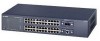
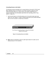
...). Connecting Devices to the Switch Note: Ethernet specifications limit the cable length between the switch and the attached device to make these connections. When attaching devices to an FS726 or an FS750, the switch's support for Auto Uplink technology allows you to attach devices using either straight-through or crossover cables (for more information about Auto Link' technology, refer to "Auto Uplink " on the switch's front panel (see Figure 4-2). installation 4-4 Front Panel of the Model...
...). Connecting Devices to the Switch Note: Ethernet specifications limit the cable length between the switch and the attached device to make these connections. When attaching devices to an FS726 or an FS750, the switch's support for Auto Uplink technology allows you to attach devices using either straight-through or crossover cables (for more information about Auto Link' technology, refer to "Auto Uplink " on the switch's front panel (see Figure 4-2). installation 4-4 Front Panel of the Model...

FS750 Reference Manual
Page 30
... switch 9. If the green Power LED does not go on . If this does not resolve the problem, refer to the power outlet on self-test (POST) to a grounded 3-pronged AC outlet. the only method of the AC power adapter cable to verify operation. Connect the female end of the supplied AC power adapter cable to Chapter 5, Troubleshooting. When power is not controlled by connecting or disconnecting the power cord. installation 4-6 When you connect...
... switch 9. If the green Power LED does not go on . If this does not resolve the problem, refer to the power outlet on self-test (POST) to a grounded 3-pronged AC outlet. the only method of the AC power adapter cable to verify operation. Connect the female end of the supplied AC power adapter cable to Chapter 5, Troubleshooting. When power is not controlled by connecting or disconnecting the power cord. installation 4-6 When you connect...

FS750 Reference Manual
Page 32
... all cables used are correct and comply with Ethernet specifications. troubleshooting 5-1 Information includes: • Troubleshooting information table • Additional troubleshooting suggestions Troubleshooting Chart Table 5-1 lists symptoms, causes, and solutions of possible problems. Table 5-1. Port connection is off or intermittnet. Make sure all products are functioning. Troubleshooting Chart Symptom Power LED is not working Solution Check the power cord connections for a defective adapter card, cable, or port by testing them in troubleshooting the NETGEAR...
... all cables used are correct and comply with Ethernet specifications. troubleshooting 5-1 Information includes: • Troubleshooting information table • Additional troubleshooting suggestions Troubleshooting Chart Table 5-1 lists symptoms, causes, and solutions of possible problems. Table 5-1. Port connection is off or intermittnet. Make sure all products are functioning. Troubleshooting Chart Symptom Power LED is not working Solution Check the power cord connections for a defective adapter card, cable, or port by testing them in troubleshooting the NETGEAR...

FS750 Reference Manual
Page 33
...'s network interface is correct. Half- Verify that the cabling is installed and configured correctly. Some collisions are normal when the connection is set to auto negotiate. Recheck the settings of the network. Make sure the attached device is operating in the required ports. Check that has a connection. Collisions are occurring on the switch and the connected device are securely positioned in half-duplex mode. Make sure the cable is powered on...
...'s network interface is correct. Half- Verify that the cabling is installed and configured correctly. Some collisions are normal when the connection is set to auto negotiate. Recheck the settings of the network. Make sure the attached device is operating in the required ports. Check that has a connection. Collisions are occurring on the switch and the connected device are securely positioned in half-duplex mode. Make sure the cable is powered on...

FS750 Reference Manual
Page 34
... duplex mode and speed if the device at the other physical aspects of the switch by implementing the new changes, one step at a time. To reset the switch, remove AC power from the switch and then reapply AC power. Network Adapter Cards Make sure the network adapter cards installed in the PCs are outside of the link supports auto negotiation. Configuration If problems occur after altering the network configuration, restore the original connections and determine the problem by resetting the switch...
... duplex mode and speed if the device at the other physical aspects of the switch by implementing the new changes, one step at a time. To reset the switch, remove AC power from the switch and then reapply AC power. Network Adapter Cards Make sure the network adapter cards installed in the PCs are outside of the link supports auto negotiation. Configuration If problems occur after altering the network configuration, restore the original connections and determine the problem by resetting the switch...

FS750 Reference Manual
Page 44
Category 5 Cable Specifications Table C-1 lists the electrical requirements of the circuitry in crossover ports, called MDI or uplink ports. The crossover function is needed and makes the right connection. Computers and workstation adapter cards are configured as part of Category 5 UTP cable. Table C-1. cabling guidelines C-3 Most repeaters and switch ports are usually media-dependent interface ports, called MDI-X or normal ports. Electrical Requirements of Category 5 Cable Specifications Category 5 Cable Requirements Number of pairs Four...
Category 5 Cable Specifications Table C-1 lists the electrical requirements of the circuitry in crossover ports, called MDI or uplink ports. The crossover function is needed and makes the right connection. Computers and workstation adapter cards are configured as part of Category 5 UTP cable. Table C-1. cabling guidelines C-3 Most repeaters and switch ports are usually media-dependent interface ports, called MDI-X or normal ports. Electrical Requirements of Category 5 Cable Specifications Category 5 Cable Requirements Number of pairs Four...

FS750 Reference Manual
Page 46
...-T Gigabit Ethernet over Category 5 Cable Overview When using the new 1000BASE-T standard, the limitations of cable installations and the steps necessary to ensure optimum performance must be partitioned or disconnected from the network. The following sections are designed to be considered. However, using patch panels, make sure that your cabling system are using telephone cable results in excessive collisions, causing the attached port...
...-T Gigabit Ethernet over Category 5 Cable Overview When using the new 1000BASE-T standard, the limitations of cable installations and the steps necessary to ensure optimum performance must be partitioned or disconnected from the network. The following sections are designed to be considered. However, using patch panels, make sure that your cabling system are using telephone cable results in excessive collisions, causing the attached port...

FS750 Reference Manual
Page 50
... and RJ-45 Connector, B-1 Customer Support, iv D Data Rate, A-1 Desktop Switching, 3-1 F Fast Ethernet Cable Guidelines, C-1 Features, 1-2 Front and Back Panels, 2-1 Fiber Optic Cables, C-8 Fiber Cable Specifications, C-8 G Gigabit Cable Guidelines, C-8 I Installation Preparing the Site, 4-2 Installing the Switch, 4-3 Installing the Switch on a Flat Surface, 4-3 Installing the Switch in a Rack, 4-3 Connecting Devices to the Switch, 4-4 Checking the Installation, 4-6 Applying AC Power, 4-6 Interface, A-1 L LED Descriptions, 2-4 N Near End Cross Talk (NEXT), C-7 Network Protocol and Standards...
... and RJ-45 Connector, B-1 Customer Support, iv D Data Rate, A-1 Desktop Switching, 3-1 F Fast Ethernet Cable Guidelines, C-1 Features, 1-2 Front and Back Panels, 2-1 Fiber Optic Cables, C-8 Fiber Cable Specifications, C-8 G Gigabit Cable Guidelines, C-8 I Installation Preparing the Site, 4-2 Installing the Switch, 4-3 Installing the Switch on a Flat Surface, 4-3 Installing the Switch in a Rack, 4-3 Connecting Devices to the Switch, 4-4 Checking the Installation, 4-6 Applying AC Power, 4-6 Interface, A-1 L LED Descriptions, 2-4 N Near End Cross Talk (NEXT), C-7 Network Protocol and Standards...


