
EN104 Installation Guide
Page 2
... transceiver, or for network expansion by connecting multiple hubs together using twisted pair or coaxial cabling • Uplink port for connecting to other hubs using simple straight-through cables • Clear front-panel light-emitting diode (LED) indicators to monitor overall hub status • Plug-and-play networking solutions for recognizing and correcting incorrect polarity on the receive pair • Compact design, enabling easy tabletop or rack-mounting installation • External power adapter • Limited...
... transceiver, or for network expansion by connecting multiple hubs together using twisted pair or coaxial cabling • Uplink port for connecting to other hubs using simple straight-through cables • Clear front-panel light-emitting diode (LED) indicators to monitor overall hub status • Plug-and-play networking solutions for recognizing and correcting incorrect polarity on the receive pair • Compact design, enabling easy tabletop or rack-mounting installation • External power adapter • Limited...

EN104 Installation Guide
Page 3
... 1 2 3 4 or Model EN116 hub LINK Rx 5 6 7 8 10 BASE-T HUB EN116 Pwr Col 1 2 3 4 5 6 7 8 1 2 3 4 LINK Rx 5 6 7 8 Mounting kit Power adapter Installation guide, Warranty & Owner Registration Card, Support Information Card 8731FA Verify that your package contains the following: • Model EN104 hub, Model EN108 hub, or Model EN116 hub • Mounting kit (for wall installation) • BNC T-connector and BNC 50 Ω terminator (only if you have purchased the Model EN108 hub or the Model EN116 hub) • This installation guide • Warranty...
... 1 2 3 4 or Model EN116 hub LINK Rx 5 6 7 8 10 BASE-T HUB EN116 Pwr Col 1 2 3 4 5 6 7 8 1 2 3 4 LINK Rx 5 6 7 8 Mounting kit Power adapter Installation guide, Warranty & Owner Registration Card, Support Information Card 8731FA Verify that your package contains the following: • Model EN104 hub, Model EN108 hub, or Model EN116 hub • Mounting kit (for wall installation) • BNC T-connector and BNC 50 Ω terminator (only if you have purchased the Model EN108 hub or the Model EN116 hub) • This installation guide • Warranty...

EN104 Installation Guide
Page 4
... Model EN104 hub 10BASE-T ports Pwr (Power) Col (Collision) 10 BASE-T HUB EN104 LINK Rx Pwr Col Normal/Uplink push button Front Panel of the Model EN108 hub 10 BASE-T HUB EN108 Pwr Col 1 2 3 4 LINK Rx 5 6 7 8 Front Panel of the Model EN116 hub 10 BASE-T HUB EN116 Pwr Col 1 2 3 4 5 6 7 8 1 2 3 4 LINK Rx 5 6 7 8 8732FA Vista 10BASE-T Network Ports with Built-in LEDs The front panel of the Model EN104 hub has four RJ-45 10BASE-T ports...
... Model EN104 hub 10BASE-T ports Pwr (Power) Col (Collision) 10 BASE-T HUB EN104 LINK Rx Pwr Col Normal/Uplink push button Front Panel of the Model EN108 hub 10 BASE-T HUB EN108 Pwr Col 1 2 3 4 LINK Rx 5 6 7 8 Front Panel of the Model EN116 hub 10 BASE-T HUB EN116 Pwr Col 1 2 3 4 5 6 7 8 1 2 3 4 LINK Rx 5 6 7 8 8732FA Vista 10BASE-T Network Ports with Built-in LEDs The front panel of the Model EN104 hub has four RJ-45 10BASE-T ports...

EN104 Installation Guide
Page 5
... corner of each vista 10BASE-T port) Active (for BNC) Rx (for BNC) Active (for AUI) Rx (for AUI) Color Activity Description Green Amber Green On Blinking On Power is supplied to the hub. Normal/Uplink Push Button The Normal/Uplink push button allows you to select Uplink (MDI) wiring for connection to select Normal (MDI-X) wiring for connection to use a crossover cable. Model EN104/EN108/EN116 Ethernet Hub Installation Guide Data collision is good.
... corner of each vista 10BASE-T port) Active (for BNC) Rx (for BNC) Active (for AUI) Rx (for AUI) Color Activity Description Green Amber Green On Blinking On Power is supplied to the hub. Normal/Uplink Push Button The Normal/Uplink push button allows you to select Uplink (MDI) wiring for connection to select Normal (MDI-X) wiring for connection to use a crossover cable. Model EN104/EN108/EN116 Ethernet Hub Installation Guide Data collision is good.

EN104 Installation Guide
Page 6
You can use the AUI port with the appropriate transceiver to connect the hub to a backbone network using thin coaxial cable. The rear panel of the Model EN116 hub 8738FA Model EN104/EN108/EN116 Ethernet Hub Installation Guide BNC port LEDs BNC port Active BNC Rx 12Vdc 1.2A -+ Rear Panel of the Model EN104 hub AUI port LEDs AUI port Power receptacle Active AUI Rx Active BNC Rx 12Vdc 1.2A -+ Rear Panel of the Model EN108 hub AUI...
You can use the AUI port with the appropriate transceiver to connect the hub to a backbone network using thin coaxial cable. The rear panel of the Model EN116 hub 8738FA Model EN104/EN108/EN116 Ethernet Hub Installation Guide BNC port LEDs BNC port Active BNC Rx 12Vdc 1.2A -+ Rear Panel of the Model EN104 hub AUI port LEDs AUI port Power receptacle Active AUI Rx Active BNC Rx 12Vdc 1.2A -+ Rear Panel of the Model EN108 hub AUI...

EN104 Installation Guide
Page 7
... provides at least 2 inches of the mounting holes on all sides for cooling. Wiring hardware, such as photocopy machine or arc welder). To install the hub on a wall, measure the distance between 0° and 40° C (32° and 104° F). Model EN104/EN108/EN116 Ethernet Hub Installation Guide Make sure your hub, prepare the installation site. Minimum 12 inches (19.68...
... provides at least 2 inches of the mounting holes on all sides for cooling. Wiring hardware, such as photocopy machine or arc welder). To install the hub on a wall, measure the distance between 0° and 40° C (32° and 104° F). Model EN104/EN108/EN116 Ethernet Hub Installation Guide Make sure your hub, prepare the installation site. Minimum 12 inches (19.68...

EN104 Installation Guide
Page 8
Model EN104/EN108/EN116 Ethernet Hub Installation Guide To connect any device equipped with a 10BASE-T Ethernet interface to the RJ-45 ports on your hub by using port 4 on the Model EN104 hub, port 8 on the Model EN108 hub, or port 16 on your hub to 328 feet (100 meters) in the illustration.) Pwr Col 1 2 3 4 5 6 Normal/Uplink 7 8 8734FA Note: Ethernet specifications limit the cable length between your PC or server and the hub to...
Model EN104/EN108/EN116 Ethernet Hub Installation Guide To connect any device equipped with a 10BASE-T Ethernet interface to the RJ-45 ports on your hub by using port 4 on the Model EN104 hub, port 8 on the Model EN108 hub, or port 16 on your hub to 328 feet (100 meters) in the illustration.) Pwr Col 1 2 3 4 5 6 Normal/Uplink 7 8 8734FA Note: Ethernet specifications limit the cable length between your PC or server and the hub to...

EN104 Installation Guide
Page 9
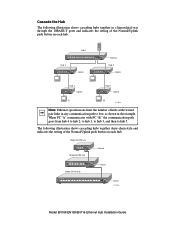
.... Use the following table. Connect the Hub to a Network Cascading refers to connecting hubs together to increase the number of ports or the number of users supported on the Model EN116 hub, use and how to set to Hub or switch Uplink Cable Used Straight-through cable Straight-through cable Crossover cable Set the Normal/Uplink Push Button If you are MDI-X (or Normal) ports. The 10BASE-T ports, with the exception of cable to PC, server, or router Normal Port 4, port 8, or port 16 set the Normal/Uplink push button...
.... Use the following table. Connect the Hub to a Network Cascading refers to connecting hubs together to increase the number of ports or the number of users supported on the Model EN116 hub, use and how to set to Hub or switch Uplink Cable Used Straight-through cable Straight-through cable Crossover cable Set the Normal/Uplink Push Button If you are MDI-X (or Normal) ports. The 10BASE-T ports, with the exception of cable to PC, server, or router Normal Port 4, port 8, or port 16 set the Normal/Uplink push button...
EN104 Installation Guide
Page 10
Model EN104 hub 10 BASE-T HUB EN104 Pwr LINK Rx Col Model EN108 hub Normal 10 BASE-T HUB EN108 Pwr Col 1 2 3 4 LINK Rx 5 6 7 8 Model EN116 hub Uplink 10 BASE-T HUB EN116 Pwr Col 1 2 3 4 5 6 7 8 1 2 3 4 LINK Rx 5 6 7 8 Uplink 8733FA Model EN104/EN108/EN116 Ethernet Hub Installation Guide The following illustration shows cascading hubs together in the example. When PC "A" communicates with twisted pair links in any communication path to hub 5. Cascade the Hub The following illustration shows cascading hubs together daisy...
Model EN104 hub 10 BASE-T HUB EN104 Pwr LINK Rx Col Model EN108 hub Normal 10 BASE-T HUB EN108 Pwr Col 1 2 3 4 LINK Rx 5 6 7 8 Model EN116 hub Uplink 10 BASE-T HUB EN116 Pwr Col 1 2 3 4 5 6 7 8 1 2 3 4 LINK Rx 5 6 7 8 Uplink 8733FA Model EN104/EN108/EN116 Ethernet Hub Installation Guide The following illustration shows cascading hubs together in the example. When PC "A" communicates with twisted pair links in any communication path to hub 5. Cascade the Hub The following illustration shows cascading hubs together daisy...

EN104 Installation Guide
Page 11
... separation marks in the coaxial cable between any two stations, and limit segments to 607 feet (185 m) in the port, and the 50 Ω terminator terminates the connection at each connected hub as just another node on the rear panel of other devices to the BNC port. Model EN104/EN108/EN116 Ethernet Hub Installation Guide Connect to a Network Using the BNC Port The BNC port on the coaxial segment.
... separation marks in the coaxial cable between any two stations, and limit segments to 607 feet (185 m) in the port, and the 50 Ω terminator terminates the connection at each connected hub as just another node on the rear panel of other devices to the BNC port. Model EN104/EN108/EN116 Ethernet Hub Installation Guide Connect to a Network Using the BNC Port The BNC port on the coaxial segment.

EN104 Installation Guide
Page 12
Refer to your transceiver documentation for connecting a thick coaxial segment. Model EN104/EN108/EN116 Ethernet Hub Installation Guide Note: All transceivers connected to most types of transceiver, you can use the AUI port to connect to the AUI port must have the signal quality error (SQE) test function disabled. With the right type of network media, including 10BASE-T twisted pair cable or thin coaxial, thick coaxial, and 10BASE-FL fiber...
Refer to your transceiver documentation for connecting a thick coaxial segment. Model EN104/EN108/EN116 Ethernet Hub Installation Guide Note: All transceivers connected to most types of transceiver, you can use the AUI port to connect to the AUI port must have the signal quality error (SQE) test function disabled. With the right type of network media, including 10BASE-T twisted pair cable or thin coaxial, thick coaxial, and 10BASE-FL fiber...

EN104 Installation Guide
Page 13
If encounter any problems, refer to "Troubleshooting" on . When power has been applied to the power outlet on the wall. Model EN104/EN108/EN116 Ethernet Hub Installation Guide Verify Installation To complete the installation, connect the power cord first to the power receptacle on the hub rear panel and then to the hub: • The green Pwr (Power) LED on the front panel is on. • The green Link LED on each connected port is on. • The green Active LED on each connected AUI port is on. • The green Active LED on each connected BNC port is on page 4.
If encounter any problems, refer to "Troubleshooting" on . When power has been applied to the power outlet on the wall. Model EN104/EN108/EN116 Ethernet Hub Installation Guide Verify Installation To complete the installation, connect the power cord first to the power receptacle on the hub rear panel and then to the hub: • The green Pwr (Power) LED on the front panel is on. • The green Link LED on each connected port is on. • The green Active LED on each connected AUI port is on. • The green Active LED on each connected BNC port is on page 4.
EN104 Installation Guide
Page 14
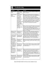
.... The port is data transmission. Refer to your transceiver documentation for instructions on the as a NETGEAR Ethernet switch or to upgrade network that there is data transmission. or defective If the network is connected. Check for cable use and Normal/Uplink push button information. Green Link LED is not blinking when there is not detecting a successful link. there is required. Model EN104/EN108/EN116 Ethernet Hub Installation Guide No action is data transmission. Troubleshooting Symptom Cause Solution Amber Col LED blinks. Amber Col LED blinks excessively...
.... The port is data transmission. Refer to your transceiver documentation for instructions on the as a NETGEAR Ethernet switch or to upgrade network that there is data transmission. or defective If the network is connected. Check for cable use and Normal/Uplink push button information. Green Link LED is not blinking when there is not detecting a successful link. there is required. Model EN104/EN108/EN116 Ethernet Hub Installation Guide No action is data transmission. Troubleshooting Symptom Cause Solution Amber Col LED blinks. Amber Col LED blinks excessively...
EN104 Installation Guide
Page 15
Hub Integrity If required, verify the integrity of the representative in working condition and the software drivers have completed all the preceding diagnoses, contact NETGEAR Customer Support. If the problem continues and you have been installed. Turn power to the Support Information Card. For the phone number of the hub by resetting it. Network Interface Cards Make sure the network interface cards installed in the workstations are in your area, refer to the hub off and then back on. Model EN104/EN108/EN116 Ethernet Hub Installation Guide
Hub Integrity If required, verify the integrity of the representative in working condition and the software drivers have completed all the preceding diagnoses, contact NETGEAR Customer Support. If the problem continues and you have been installed. Turn power to the Support Information Card. For the phone number of the hub by resetting it. Network Interface Cards Make sure the network interface cards installed in the workstations are in your area, refer to the hub off and then back on. Model EN104/EN108/EN116 Ethernet Hub Installation Guide

EN104 Installation Guide
Page 16
Power Consumption Model EN104 hub 11.0 W Model EN108 hub 16.5 W Model EN116 hub 20.5 W DC Output Voltage (Power Adapter): Model EN104 hub 7.5 V DC@ 1A max. Technical Specifications General Specifications Network Protocol and Standards Compatibility IEEE 802.3i, 10BASE-T, 10BASE-2, 10BASE-5 Ethernet Data Rate 10 Mbps, Manchester encoded Interface 10BASE-T ports (RJ-45), BNC port, AUI port (Model EN108 hub and Model EN116 hub only) Max. Model EN116 hub 12 V DC @ 1.2A max., Physical Specifications Dimensions: Model EN104 hub 3.7 by...
Power Consumption Model EN104 hub 11.0 W Model EN108 hub 16.5 W Model EN116 hub 20.5 W DC Output Voltage (Power Adapter): Model EN104 hub 7.5 V DC@ 1A max. Technical Specifications General Specifications Network Protocol and Standards Compatibility IEEE 802.3i, 10BASE-T, 10BASE-2, 10BASE-5 Ethernet Data Rate 10 Mbps, Manchester encoded Interface 10BASE-T ports (RJ-45), BNC port, AUI port (Model EN108 hub and Model EN116 hub only) Max. Model EN116 hub 12 V DC @ 1.2A max., Physical Specifications Dimensions: Model EN104 hub 3.7 by...

EN104 Installation Guide
Page 17
... code PWR-002-004 PWR-002-005 PWR-002-006 PWR-002-008 PWR-002-010 EN108, EN116 Power adapter (12 V DC, 1.2 A), North America Power adapter (12 V DC, 1.2 A), Japan Power adapter (12 V DC, 1.2 A), Europe Power adapter (12 V DC, 1.2 A), United Kingdom Power adapter (12 V DC, 1.2 A), Australia Model EN104/EN108/EN116 Ethernet Hub Installation Guide Replacement Power Adapter If, for any reason, the power adapter for any of the hubs fails, contact NETGEAR immediately to order a replacement adapter. Use the following table...
... code PWR-002-004 PWR-002-005 PWR-002-006 PWR-002-008 PWR-002-010 EN108, EN116 Power adapter (12 V DC, 1.2 A), North America Power adapter (12 V DC, 1.2 A), Japan Power adapter (12 V DC, 1.2 A), Europe Power adapter (12 V DC, 1.2 A), United Kingdom Power adapter (12 V DC, 1.2 A), Australia Model EN104/EN108/EN116 Ethernet Hub Installation Guide Replacement Power Adapter If, for any reason, the power adapter for any of the hubs fails, contact NETGEAR immediately to order a replacement adapter. Use the following table...

EN104 Installation Guide
Page 18
... case users will be necessary to the products described in the Radio Interference Regulations of the Canadian Department of Communications. Canadian Department of Communications Radio Interference Regulations This digital apparatus (NETGEAR Model EN104 hub, Model EN108 hub, and Model EN116 hub) does not exceed the Class A limits for compliance with the conditions set by the Voluntary Control Council for Interference by Data...
... case users will be necessary to the products described in the Radio Interference Regulations of the Canadian Department of Communications. Canadian Department of Communications Radio Interference Regulations This digital apparatus (NETGEAR Model EN104 hub, Model EN108 hub, and Model EN116 hub) does not exceed the Class A limits for compliance with the conditions set by the Voluntary Control Council for Interference by Data...


