EN104TP Installation Guide
Page 2
... cables • Clear front-panel light-emitting diode (LED) indicators to monitor overall hub status • Plug-and-play networking solutions for recognizing and correcting incorrect polarity on the receive pair • Compact design, enabling easy tabletop or rack-mounting installation • External power adapter • Limited five-year warranty on the unit and one-year warranty on the Model EN108TP hub) vista 10BASE-T network ports (RJ-45) that refers...
... cables • Clear front-panel light-emitting diode (LED) indicators to monitor overall hub status • Plug-and-play networking solutions for recognizing and correcting incorrect polarity on the receive pair • Compact design, enabling easy tabletop or rack-mounting installation • External power adapter • Limited five-year warranty on the unit and one-year warranty on the Model EN108TP hub) vista 10BASE-T network ports (RJ-45) that refers...
EN104TP Installation Guide
Page 3
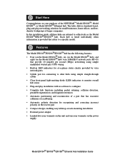
... Model EN106TP hub or Model EN108TP hub 10 BASE-T HUB EN104TP 10 BASE-T HUB EN106TP Pwr Col Link/Rx Partition Normal/Uplink 1 2 3 4 5 6 Mounting kit 10 BASE-T HUB EN108TP Pwr Col 1 2 3 4 5 6 7 8 Power adapter and cord Installation guide, Warranty & Owner Registration Card Verify that your package contains the following: • Model EN104TP hub, Model EN106TP hub, or Model EN108TP hub • Mounting kit (for wall installation) • This installation guide • Warranty & Owner Registration Card • Power adapter 8722FA Model EN104TP/EN106TP/EN108TP Ethernet...
... Model EN106TP hub or Model EN108TP hub 10 BASE-T HUB EN104TP 10 BASE-T HUB EN106TP Pwr Col Link/Rx Partition Normal/Uplink 1 2 3 4 5 6 Mounting kit 10 BASE-T HUB EN108TP Pwr Col 1 2 3 4 5 6 7 8 Power adapter and cord Installation guide, Warranty & Owner Registration Card Verify that your package contains the following: • Model EN104TP hub, Model EN106TP hub, or Model EN108TP hub • Mounting kit (for wall installation) • This installation guide • Warranty & Owner Registration Card • Power adapter 8722FA Model EN104TP/EN106TP/EN108TP Ethernet...
EN104TP Installation Guide
Page 4
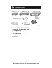
... of the Model EN104TP hub 10BASE-T ports Pwr (Power) Col (Collision) 10 BASE-T HUB EN104TP Pwr LINK Rx Col Normal/Uplink push button Front Panel of the Model EN106TP hub 10 BASE-T HUB EN106TP Pwr Col LINK Rx Normal/Uplink 1 2 3 4 5 6 Front Panel of the Model EN108TP hub 10 BASE-T HUB EN108TP Pwr Col 1 2 3 4 LINK Rx 5 6 7 8 8723FA Vista 10BASE-T Network Ports with Built-in LEDs The front panel of the Model EN104TP hub has four...
... of the Model EN104TP hub 10BASE-T ports Pwr (Power) Col (Collision) 10 BASE-T HUB EN104TP Pwr LINK Rx Col Normal/Uplink push button Front Panel of the Model EN106TP hub 10 BASE-T HUB EN106TP Pwr Col LINK Rx Normal/Uplink 1 2 3 4 5 6 Front Panel of the Model EN108TP hub 10 BASE-T HUB EN108TP Pwr Col 1 2 3 4 LINK Rx 5 6 7 8 8723FA Vista 10BASE-T Network Ports with Built-in LEDs The front panel of the Model EN104TP hub has four...
EN104TP Installation Guide
Page 5
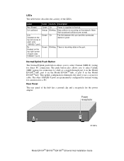
... a receptacle for connection to use a crossover cable. The link between this port and the connected device is incoming data on the network. The push button also allows you to a PC. Label Color Activity Description Pwr (Power) Col (collision) Link (located on the top left corner of each vista 10BASE-T port) Green Amber Green Green On Blinking On Blinking Power is occurring on the port. There is good. LEDs The table below describes...
... a receptacle for connection to use a crossover cable. The link between this port and the connected device is incoming data on the network. The push button also allows you to a PC. Label Color Activity Description Pwr (Power) Col (collision) Link (located on the top left corner of each vista 10BASE-T port) Green Amber Green Green On Blinking On Blinking Power is occurring on the port. There is good. LEDs The table below describes...
EN104TP Installation Guide
Page 6
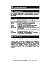
... on all around the hub for cooling. Install the Hub To install your hub, prepare the installation site. Model EN104TP/EN106TP/EN108TP Ethernet Hub Installation Guide No nearby heat sources such as punchdown blocks or patch panels, should be connected, is positioned with the mounting kit included in room or wiring closet. Front and back clearance for service access and maintenance. To install the hub on a wall, measure...
... on all around the hub for cooling. Install the Hub To install your hub, prepare the installation site. Model EN104TP/EN106TP/EN108TP Ethernet Hub Installation Guide No nearby heat sources such as punchdown blocks or patch panels, should be connected, is positioned with the mounting kit included in room or wiring closet. Front and back clearance for service access and maintenance. To install the hub on a wall, measure...
EN104TP Installation Guide
Page 7
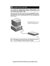
... the Model EN108TP hub, set the Normal/Uplink push button to a PC, use a regular straight-through UTP cable. If you are connecting using twisted pair Ethernet cables. To connect any device equipped with a 10BASE-T Ethernet interface to the RJ-45 ports on your PC or server and the hub to 328 feet (100 meters) in the illustration.) Pwr Col 1 2 3 4 5 Normal/Uplink 6 8726FA Note: Ethernet specifications limit the cable length between your hub by using port...
... the Model EN108TP hub, set the Normal/Uplink push button to a PC, use a regular straight-through UTP cable. If you are connecting using twisted pair Ethernet cables. To connect any device equipped with a 10BASE-T Ethernet interface to the RJ-45 ports on your PC or server and the hub to 328 feet (100 meters) in the illustration.) Pwr Col 1 2 3 4 5 Normal/Uplink 6 8726FA Note: Ethernet specifications limit the cable length between your hub by using port...
EN104TP Installation Guide
Page 8
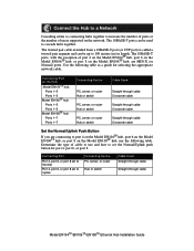
... type of users supported on the Hub Model EN104TP hub: Ports 1-3 Ports 1-3 Model EN106TP hub: Ports 1-5 Ports 1-5 Model EN108TP hub: Ports 1-7 Ports 1-7 Connecting Device PC, server, or router Hub or switch PC, server, or router Hub or switch PC, server, or router Hub or switch Cable Used Straight-through cable Crossover cable Straight-through cable Crossover cable Straight-through cable Model EN104TP/EN106TP/EN108TP Ethernet Hub Installation Guide Connecting Port on the network. Use the following table. Connecting Port Port 4, port 6, or port 8 set to use the following table...
... type of users supported on the Hub Model EN104TP hub: Ports 1-3 Ports 1-3 Model EN106TP hub: Ports 1-5 Ports 1-5 Model EN108TP hub: Ports 1-7 Ports 1-7 Connecting Device PC, server, or router Hub or switch PC, server, or router Hub or switch PC, server, or router Hub or switch Cable Used Straight-through cable Crossover cable Straight-through cable Crossover cable Straight-through cable Model EN104TP/EN106TP/EN108TP Ethernet Hub Installation Guide Connecting Port on the network. Use the following table. Connecting Port Port 4, port 6, or port 8 set to use the following table...
EN104TP Installation Guide
Page 9
.../EN106TP/EN108TP Ethernet Hub Installation Guide Model EN108TP hub 10 BASE-T HUB EN108TP Pwr Col 1 2 3 4 5 6 7 8 Normal Model EN108TP hub Model EN106TP hub 10 BASE-T HUB EN108TP Pwr Col 1 2 3 4 5 6 7 8 Uplink 10 BASE-T HUB EN106TP Pwr Col Link/Rx Partition Normal/Uplink 1 2 3 4 5 6 Uplink Model EN104TP hubs Uplink Uplink A B 8727FA Note: Ethernet specifications limit the number of hubs with PC "B," the communication path goes from hub 4 to hub 2, to hub 1, to hub 3, and then to five, as shown in a hierarchical star through the 10BASE-T ports and...
.../EN106TP/EN108TP Ethernet Hub Installation Guide Model EN108TP hub 10 BASE-T HUB EN108TP Pwr Col 1 2 3 4 5 6 7 8 Normal Model EN108TP hub Model EN106TP hub 10 BASE-T HUB EN108TP Pwr Col 1 2 3 4 5 6 7 8 Uplink 10 BASE-T HUB EN106TP Pwr Col Link/Rx Partition Normal/Uplink 1 2 3 4 5 6 Uplink Model EN104TP hubs Uplink Uplink A B 8727FA Note: Ethernet specifications limit the number of hubs with PC "B," the communication path goes from hub 4 to hub 2, to hub 1, to hub 3, and then to five, as shown in a hierarchical star through the 10BASE-T ports and...
EN104TP Installation Guide
Page 10
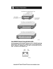
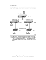
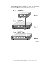
The following illustration shows cascading hubs together daisy-chain style and indicates the setting of the Normal/Uplink push button on each hub. Model EN104TP hub 10 BASE-T HUB EN104TP Normal Model EN106TP hub 10 BASE-T HUB EN106TP Pwr Col Link/Rx Partition Normal/Uplink 1 2 3 4 5 6 Model EN108TP hub 10 BASE-T HUB EN108TP Pwr Col 1 2 3 4 5 6 7 8 Uplink Uplink 8728FA Model EN104TP/EN106TP/EN108TP Ethernet Hub Installation Guide
The following illustration shows cascading hubs together daisy-chain style and indicates the setting of the Normal/Uplink push button on each hub. Model EN104TP hub 10 BASE-T HUB EN104TP Normal Model EN106TP hub 10 BASE-T HUB EN106TP Pwr Col Link/Rx Partition Normal/Uplink 1 2 3 4 5 6 Model EN108TP hub 10 BASE-T HUB EN108TP Pwr Col 1 2 3 4 5 6 7 8 Uplink Uplink 8728FA Model EN104TP/EN106TP/EN108TP Ethernet Hub Installation Guide
EN104TP Installation Guide
Page 11
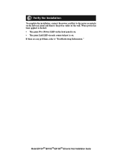
When power has been applied to the hub: • The green Pwr (Power) LED on the front panel is on. • The green Link LED on each connected port is on the wall. Verify the Installation To complete the installation, connect the power cord first to the power receptacle on the hub rear panel and then to the power outlet on . If there are any problems, refer to "Troubleshooting Information." Model EN104TP/EN106TP/EN108TP Ethernet Hub Installation Guide
When power has been applied to the hub: • The green Pwr (Power) LED on the front panel is on. • The green Link LED on each connected port is on the wall. Verify the Installation To complete the installation, connect the power cord first to the power receptacle on the hub rear panel and then to the power outlet on . If there are any problems, refer to "Troubleshooting Information." Model EN104TP/EN106TP/EN108TP Ethernet Hub Installation Guide
EN104TP Installation Guide
Page 12
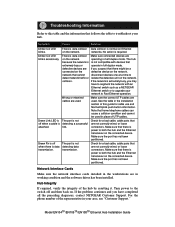
... operate in working condition and the software driver has been installed. Model EN104TP/EN106TP/EN108TP Ethernet Hub Installation Guide networks. There is attached. Note that are If you have to Fast Ethernet operation. transmission. Make sure the port has not been partitioned. No action is not detecting a successful link. If the network is data detecting data transmission. Wrong or miswired cables are in full-duplex mode. Green Link LED is off The port is not...
... operate in working condition and the software driver has been installed. Model EN104TP/EN106TP/EN108TP Ethernet Hub Installation Guide networks. There is attached. Note that are If you have to Fast Ethernet operation. transmission. Make sure the port has not been partitioned. No action is not detecting a successful link. If the network is data detecting data transmission. Wrong or miswired cables are in full-duplex mode. Green Link LED is off The port is not...
EN104TP Installation Guide
Page 13
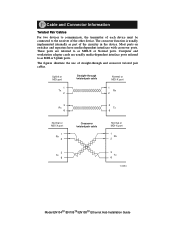
Most ports on switches and repeaters have media-dependent interfaces with crossover ports. These ports are usually media-dependent interface ports referred to as MDI or Uplink ports. The figures illustrate the use of the other device. Uplink or MDI port 1 Tx 2 Straight-through and crossover twisted pair cables. Computer and workstation adapter cards are referred to as part of the circuitry in the device. CTaebclhenaicnadl CSopnenciefcictaotrioInnfsormation Twisted...
Most ports on switches and repeaters have media-dependent interfaces with crossover ports. These ports are usually media-dependent interface ports referred to as MDI or Uplink ports. The figures illustrate the use of the other device. Uplink or MDI port 1 Tx 2 Straight-through and crossover twisted pair cables. Computer and workstation adapter cards are referred to as part of the circuitry in the device. CTaebclhenaicnadl CSopnenciefcictaotrioInnfsormation Twisted...
EN104TP Installation Guide
Page 14
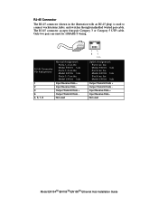
... Assignment Normal Assignment: Ports 1-3 on the Model EN104TP hub Ports 1-5 on the Model EN106TP hub Ports 1-7 on the Model EN108TP hub 1 Input Receive Data + 2 Input Receive Data - 3 Output Transmit Data + 6 Output Transmit Data - 4, 5, 7, 8 Not used 81 711EA Uplink Assignment: Port 4 on the Model EN104TP hub Port 6 on the Model EN106TP hub Port 8 on the Model EN108TP hub Output Transmit Data + Output Transmit Data Input Receive Data + Input Receive Data Not used to connect workstations, hubs, and switches through unshielded twisted pair cable. The RJ-45...
... Assignment Normal Assignment: Ports 1-3 on the Model EN104TP hub Ports 1-5 on the Model EN106TP hub Ports 1-7 on the Model EN108TP hub 1 Input Receive Data + 2 Input Receive Data - 3 Output Transmit Data + 6 Output Transmit Data - 4, 5, 7, 8 Not used 81 711EA Uplink Assignment: Port 4 on the Model EN104TP hub Port 6 on the Model EN106TP hub Port 8 on the Model EN108TP hub Output Transmit Data + Output Transmit Data Input Receive Data + Input Receive Data Not used to connect workstations, hubs, and switches through unshielded twisted pair cable. The RJ-45...
EN104TP Installation Guide
Page 15
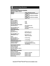
Technical Specifications General Specifications Network Protocol and Standards Compatibility IEEE 802.3i, 10BASE-T Ethernet Data Rate 10 Mbps, Manchester encoded Interface 4 10BASE-T ports (RJ-45) on the Model EN104TP hub 6 10BASE-T ports (RJ-45) on the Model EN106TP hub 8 10BASE-T ports (RJ-45) on the Model EN108TP hub Power Power Consumption: Model EN104TP hub Model EN106TP hub Model EN108TP hub 3.5 W 7.2 W 13.7 W DC output voltage (Power adapter): Model EN104TP hub 5V DC @ 800 mA max. Model EN106TP hub and Model EN108TP hub 47 to 63 Hz 12V DC...
Technical Specifications General Specifications Network Protocol and Standards Compatibility IEEE 802.3i, 10BASE-T Ethernet Data Rate 10 Mbps, Manchester encoded Interface 4 10BASE-T ports (RJ-45) on the Model EN104TP hub 6 10BASE-T ports (RJ-45) on the Model EN106TP hub 8 10BASE-T ports (RJ-45) on the Model EN108TP hub Power Power Consumption: Model EN104TP hub Model EN106TP hub Model EN108TP hub 3.5 W 7.2 W 13.7 W DC output voltage (Power adapter): Model EN104TP hub 5V DC @ 800 mA max. Model EN106TP hub and Model EN108TP hub 47 to 63 Hz 12V DC...
EN104TP Installation Guide
Page 17
... radioélectrique du ministère des Communications du Canada. Model EN104TP/EN106TP/EN108TP Ethernet Hub Installation Guide Please refer to test the series for radio-noise emissions from digital apparatus as radios and TV receivers. This equipment generates, uses, and can radiate radio frequency energy. EN 55 022 Statement This is to Part 15 of the FCC rules. The operation...
... radioélectrique du ministère des Communications du Canada. Model EN104TP/EN106TP/EN108TP Ethernet Hub Installation Guide Please refer to test the series for radio-noise emissions from digital apparatus as radios and TV receivers. This equipment generates, uses, and can radiate radio frequency energy. EN 55 022 Statement This is to Part 15 of the FCC rules. The operation...


