User Guide
Page 8
... ...2-11 Connectors ...2-13 Button ...2-22 Slots ...2-23 Chapter 3 BIOS Setup 3-1 Entering Setup ...3-2 The Main Menu ...3-4 Standard CMOS Features 3-6 Advanced BIOS Features 3-8 Integrated Peripherals 3-11 Power Management Setup 3-13 PNP/PCI Configurations 3-16 H/W Monitor ...3-18 Cell Menu ...3-19 Load Fail-Safe/ Optimized Defaults 3-23 BIOS Setting Password 3-24 Appendix A Creative Sound Blaster A-1 Hardware Setup A-2 Installing...
... ...2-11 Connectors ...2-13 Button ...2-22 Slots ...2-23 Chapter 3 BIOS Setup 3-1 Entering Setup ...3-2 The Main Menu ...3-4 Standard CMOS Features 3-6 Advanced BIOS Features 3-8 Integrated Peripherals 3-11 Power Management Setup 3-13 PNP/PCI Configurations 3-16 H/W Monitor ...3-18 Cell Menu ...3-19 Load Fail-Safe/ Optimized Defaults 3-23 BIOS Setting Password 3-24 Appendix A Creative Sound Blaster A-1 Hardware Setup A-2 Installing...
User Guide
Page 35
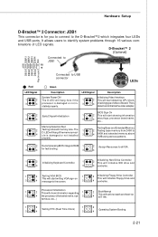
...Green 1 2 3 4 LEDs Description LED Signal Description System Power ON The D-LED will set low stack and boot via 3 4 the processor (like brand name, sys- 3 4 INT 19h. properly. 1 2 Decompressing BIOS image to RAM 1 2 Assign Resources to all ISA. 3 4 for you to ... 1 2 Initializing Keyboard Controller. 1 2 Initializing Hard Drive Controller This will initialize IDE drive and 3 4 3 4 controller. 1 2 Testing VGA BIOS 1 2 Initializing Floppy Drive Controller This will start writing VGA sign-on This will initialize Floppy Drive and 3 4 message to 3 D-LED will start...
...Green 1 2 3 4 LEDs Description LED Signal Description System Power ON The D-LED will set low stack and boot via 3 4 the processor (like brand name, sys- 3 4 INT 19h. properly. 1 2 Decompressing BIOS image to RAM 1 2 Assign Resources to all ISA. 3 4 for you to ... 1 2 Initializing Keyboard Controller. 1 2 Initializing Hard Drive Controller This will initialize IDE drive and 3 4 3 4 controller. 1 2 Testing VGA BIOS 1 2 Initializing Floppy Drive Controller This will start writing VGA sign-on This will initialize Floppy Drive and 3 4 message to 3 D-LED will start...
User Guide
Page 37
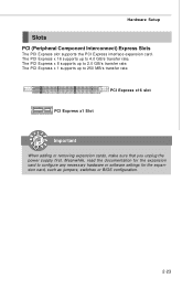
... or removing expansion cards, make sure that you unplug the power supply first. The PCI Express x 8 supports up to configure any necessary hardware or software settings for the expansion card, such as jumpers, switches or...
... or removing expansion cards, make sure that you unplug the power supply first. The PCI Express x 8 supports up to configure any necessary hardware or software settings for the expansion card, such as jumpers, switches or...
User Guide
Page 41
You may need to run SETUP. ² You want to configure the system for customized features. 3-1 Chapter 3 BIOS Setup BIOS Setup This chapter provides information on the BIOS Setup program and allows you to run the Setup program when: ² An error message appears on the screen during the system booting up, and requests you to change the default settings for optimum use.
You may need to run SETUP. ² You want to configure the system for customized features. 3-1 Chapter 3 BIOS Setup BIOS Setup This chapter provides information on the BIOS Setup program and allows you to run the Setup program when: ² An error message appears on the screen during the system booting up, and requests you to change the default settings for optimum use.
User Guide
Page 44
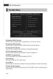
... appears if your PC health status. Cell Menu Use this menu to setup the items of AMI® special enhanced features. Advanced BIOS Features Use this menu to specify your settings for integrated peripherals. H/W Monitor This entry shows your system supports PnP/PCI. Load Fail-Safe Defaults Use this menu for basic... system configurations, such as time, date etc. MS-7320 Mainboard The Main Menu Standard CMOS Features Use this menu to load the default values set by the BIOS vendor for stable system performance. 3-4
... appears if your PC health status. Cell Menu Use this menu to setup the items of AMI® special enhanced features. Advanced BIOS Features Use this menu to specify your settings for integrated peripherals. H/W Monitor This entry shows your system supports PnP/PCI. Load Fail-Safe Defaults Use this menu for basic... system configurations, such as time, date etc. MS-7320 Mainboard The Main Menu Standard CMOS Features Use this menu to load the default values set by the BIOS vendor for stable system performance. 3-4
User Guide
Page 45
BIOS Setting Password Use this menu to load the default values set the password for optimal performance of the mainboard. Exit Without Saving Abandon all changes and exit setup. 3-5 Save & Exit Setup Save changes to CMOS and exit setup. BIOS Setup Load Optimized Defaults Use this menu to set by the mainboard manufacturer specifically for BIOS.
BIOS Setting Password Use this menu to load the default values set the password for optimal performance of the mainboard. Exit Without Saving Abandon all changes and exit setup. 3-5 Save & Exit Setup Save changes to CMOS and exit setup. BIOS Setup Load Optimized Defaults Use this menu to set by the mainboard manufacturer specifically for BIOS.
User Guide
Page 46
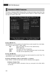
...Sun to Sat, determined by numeric function keys. through Dec. Primary IDE Master/ Slave & Serial-ATA 1~6 Channel Press to set the system to the date that you connected to the IDE/ SATA c on n ec t ors . 3-6 Device/ ... will showing the device information that you want in each item. Date (MM:DD:YY) This allows you to set the system time that you want (usually the current date). day Day of the week, from Jan. MS-7320... date The date from 1 to 31 can be keyed by BIOS. Time (HH:MM :SS) This allows you to enter the sub-menu, and the following screen appears...
...Sun to Sat, determined by numeric function keys. through Dec. Primary IDE Master/ Slave & Serial-ATA 1~6 Channel Press to set the system to the date that you connected to the IDE/ SATA c on n ec t ors . 3-6 Device/ ... will showing the device information that you want in each item. Date (MM:DD:YY) This allows you to set the system time that you want (usually the current date). day Day of the week, from Jan. MS-7320... date The date from 1 to 31 can be keyed by BIOS. Time (HH:MM :SS) This allows you to enter the sub-menu, and the following screen appears...
User Guide
Page 47
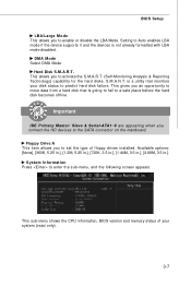
...DM A M ode Select DMA Mode. Available options: [None], [360K, 5.25 in.], [1.2M, 5.25 in.], [720K, 3.5 in.], [1.44M, 3.5 in.], [2.88M, 3.5 in.]. BIOS Setup LBA/Large M ode This allows you to set the type of your disk status to predict hard disk failure. This gives you an opportunity to a safe place before the... hard disk becomes offline. System Information Press to enable or disable the LBA Mode. Setting to Auto enables LBA mode if the device supports it and the devices is going to fail to move data from a hard disk that monitors...
...DM A M ode Select DMA Mode. Available options: [None], [360K, 5.25 in.], [1.2M, 5.25 in.], [720K, 3.5 in.], [1.44M, 3.5 in.], [2.88M, 3.5 in.]. BIOS Setup LBA/Large M ode This allows you to set the type of your disk status to predict hard disk failure. This gives you an opportunity to a safe place before the... hard disk becomes offline. System Information Press to enable or disable the LBA Mode. Setting to Auto enables LBA mode if the device supports it and the devices is going to fail to move data from a hard disk that monitors...
User Guide
Page 48
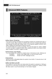
...skip some check items. Boot Up Num-Lock LED This setting is powered on . The only time when you to update the BIOS. To successfully update the BIOS, you should enable this Flash BIOS Protection function. W hen enabled, the BIOS' data cannot be changed when attempting to use the ... you want to show the company logo on the bootup screen. Setting to [Off] will allow users to update the BIOS with a Flash utility. MS-7320 Mainboard Advanced BIOS Features Boot Sector Protection This function protects the BIOS from accidental corruption by unauthorized users or computer viruses.
...skip some check items. Boot Up Num-Lock LED This setting is powered on . The only time when you to update the BIOS. To successfully update the BIOS, you should enable this Flash BIOS Protection function. W hen enabled, the BIOS' data cannot be changed when attempting to use the ... you want to show the company logo on the bootup screen. Setting to [Off] will allow users to update the BIOS with a Flash utility. MS-7320 Mainboard Advanced BIOS Features Boot Sector Protection This function protects the BIOS from accidental corruption by unauthorized users or computer viruses.
User Guide
Page 49
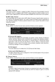
BIOS Setup IOAPIC Function This field is able to run in APIC mode. CPU Feature Press to enter the sub-menu and the following screen appears: HPET The HPET (High Precision Event Timers) is a component that is part of malicious "buffer overflow" attacks when combined with a supporting operating system. Set Limit CPUID MaxVal...
BIOS Setup IOAPIC Function This field is able to run in APIC mode. CPU Feature Press to enter the sub-menu and the following screen appears: HPET The HPET (High Precision Event Timers) is a component that is part of malicious "buffer overflow" attacks when combined with a supporting operating system. Set Limit CPUID MaxVal...
User Guide
Page 50
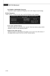
Boot From Other Device Setting the option to [Yes] allows the system to try to boot from the 1st/ 2nd/ 3rd boot device. 3-10 if the system fails to boot from other device. Boot Sequence Press to enter the sub-menu and the following screen appears: 1st/ 2nd/ 3rd Boot Device The items allow you to set the first/ second/ third boot device where BIOS attempts to south beidge. MS-7320 Mainboard C55(NB) to NVIDIA(SB) Frequency This item is used to specify the frequency from north bridge to load the disk operating system.
Boot From Other Device Setting the option to [Yes] allows the system to try to boot from the 1st/ 2nd/ 3rd boot device. 3-10 if the system fails to boot from other device. Boot Sequence Press to enter the sub-menu and the following screen appears: 1st/ 2nd/ 3rd Boot Device The items allow you to set the first/ second/ third boot device where BIOS attempts to south beidge. MS-7320 Mainboard C55(NB) to NVIDIA(SB) Frequency This item is used to specify the frequency from north bridge to load the disk operating system.
User Guide
Page 51
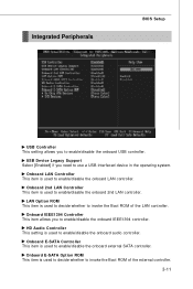
HD Audio Controller This setting is used to enable/disable the onboard audio controller. LAN Option ROM This item is used to decide whether to enable/disable the onboard external ... device in the operating system. Onboard IEEE1394 Controller This item allows you need to enable/disable the onboard 2nd LAN controller. Integrated Peripherals BIOS Setup USB Controller This setting allows you to invoke the Boot ROM of the LAN controller. Onbaord E-SATA Option ROM This item is used to decide whether to...
HD Audio Controller This setting is used to enable/disable the onboard audio controller. LAN Option ROM This item is used to decide whether to enable/disable the onboard external ... device in the operating system. Onboard IEEE1394 Controller This item allows you need to enable/disable the onboard 2nd LAN controller. Integrated Peripherals BIOS Setup USB Controller This setting allows you to invoke the Boot ROM of the LAN controller. Onbaord E-SATA Option ROM This item is used to decide whether to...
User Guide
Page 53
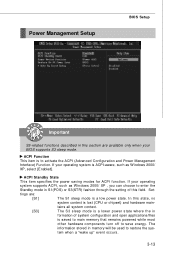
...saving modes for ACPI function. The information stored in this section are : [S1] The S1 sleep mode is to save energy. Power Management Setup BIOS Setup Important S3-related functions described in memory will be used to restore the system when a "wake up" event occurs. 3-13 If your ...to main memory that remains powered while most other hardware components turn off to activate the ACPI (Advanced Configuration and Power Management Interface) Function. Set- tains all system context. [S3] The S3 sleep mode is a lower power state where the in S1(POS) or S3(STR) fashion through...
...saving modes for ACPI function. The information stored in this section are : [S1] The S1 sleep mode is to save energy. Power Management Setup BIOS Setup Important S3-related functions described in memory will be used to restore the system when a "wake up" event occurs. 3-13 If your ...to main memory that remains powered while most other hardware components turn off to activate the ACPI (Advanced Configuration and Power Management Interface) Function. Set- tains all system context. [S3] The S3 sleep mode is a lower power state where the in S1(POS) or S3(STR) fashion through...

User Guide
Page 55
Resume by Onbaord LAN W hen set to [Enabled], the feature allows your system to enable or disable the feature of booting up the system on LAN device. BIOS Setup Resume by RTC Alarm The field is used to be awakened from the power saving modes through any event on a scheduled time/date. 3-15
Resume by Onbaord LAN W hen set to [Enabled], the feature allows your system to enable or disable the feature of booting up the system on LAN device. BIOS Setup Resume by RTC Alarm The field is used to be awakened from the power saving modes through any event on a scheduled time/date. 3-15

User Guide
Page 57
... for PCI and PnP devices. IRQ 3/4/5/7/9/10/11/14/15 These items specify the bus where the specified IRQ line is configured by the system BIOS. The available IRQ pool is ready, the system will still be removed from the pool of the operating system, it . All IRQs used . If all... IRQs are set to the onboard PCI IDE, IRQ 9 will interrupt itself and perform the service required by reading the ESCD NVRAM. When an I /O device. 3-17 Onboard I /O are...
... for PCI and PnP devices. IRQ 3/4/5/7/9/10/11/14/15 These items specify the bus where the specified IRQ line is configured by the system BIOS. The available IRQ pool is ready, the system will still be removed from the pool of the operating system, it . All IRQs used . If all... IRQs are set to the onboard PCI IDE, IRQ 9 will interrupt itself and perform the service required by reading the ESCD NVRAM. When an I /O device. 3-17 Onboard I /O are...
User Guide
Page 59
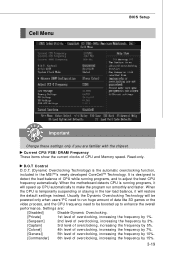
... D.O.T. (Dynamic Overclocking Technology) is temporarily suspending or staying in the MSITM's newly developed CoreCellTM Technology. Settings are familiar with the chipset. Read-only. Cell Menu BIOS Setup Important Change these settings only if you are : [Disabled] Disable Dynamic Overclocking. [Private] 1st level of overclocking, increasing ... the frequency by 10%. [Commander] 6th level of overclocking, increasing the frequency by 15%. 3-19 W hen the motherboard detects CPU is designed to detect the load balance of CPU while running programs, it will restore the default...
... D.O.T. (Dynamic Overclocking Technology) is temporarily suspending or staying in the MSITM's newly developed CoreCellTM Technology. Settings are familiar with the chipset. Read-only. Cell Menu BIOS Setup Important Change these settings only if you are : [Disabled] Disable Dynamic Overclocking. [Private] 1st level of overclocking, increasing ... the frequency by 10%. [Commander] 6th level of overclocking, increasing the frequency by 15%. 3-19 W hen the motherboard detects CPU is designed to detect the load balance of CPU while running programs, it will restore the default...
User Guide
Page 61
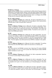
... 3-21 This item applies only when synchronous DRAM is adjustable. TRC W hen the Memory Timings sets to retain data. Selecting [Manual] allows users to [Manual], the field is controlled by BIOS based on the configurations on the DRAM module. It specifies the amount of delay (in clock... cycles) that must elapse after receiving it. This setting determines the time RAS takes to be precharged. BIOS Setup Memory Timings Selects whether DRAM timing is adjustable. Setting to [Auto By SPD] enables DRAM timings and the following related items manually. TRAS ...
... 3-21 This item applies only when synchronous DRAM is adjustable. TRC W hen the Memory Timings sets to retain data. Selecting [Manual] allows users to [Manual], the field is controlled by BIOS based on the configurations on the DRAM module. It specifies the amount of delay (in clock... cycles) that must elapse after receiving it. This setting determines the time RAS takes to be precharged. BIOS Setup Memory Timings Selects whether DRAM timing is adjustable. Setting to [Auto By SPD] enables DRAM timings and the following related items manually. TRAS ...

User Guide
Page 63
... the mainboard manufacturer specifically for stable system performance. The Optimized Defaults are the default values set by the BIOS vendor for optimal performance of the BIOS settings to restore all of the mainboard. BIOS Setup Load Fail-Safe/ Optimized Defaults The two options on the main menu allow users to the default Fail-Safe or...
... the mainboard manufacturer specifically for stable system performance. The Optimized Defaults are the default values set by the BIOS vendor for optimal performance of the BIOS settings to restore all of the mainboard. BIOS Setup Load Fail-Safe/ Optimized Defaults The two options on the main menu allow users to the default Fail-Safe or...
User Guide
Page 64
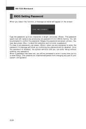
...system configuration. 3-24 A message will boot and you are prompted to enter the password. This prevents an unauthorized person from changing any previously set password from CMOS memory. You may also press to abort the selection and not enter a password. You will be prompted to confirm the ...a message as below will appear on the screen: Type the password, up confirming the password will be disabled. W hen a password has been set password, just press when you can enter Setup without entering any password. MS-7320 Mainboard BIOS Setting Password W hen you try to enter Setup.
...system configuration. 3-24 A message will boot and you are prompted to enter the password. This prevents an unauthorized person from changing any previously set password from CMOS memory. You may also press to abort the selection and not enter a password. You will be prompted to confirm the ...a message as below will appear on the screen: Type the password, up confirming the password will be disabled. W hen a password has been set password, just press when you can enter Setup without entering any password. MS-7320 Mainboard BIOS Setting Password W hen you try to enter Setup.
User Guide
Page 82
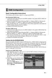
... --- Define a New Array window will reboot right away. Initialize the NVRAID Array Disks. Setting Up the NVRAID BIOS Be sure to enable the RAID mode for SATA devices in the system BIOS. (Refer the bios section for details.) 2. After rebooting your PC, wait until you see the RAID software ... to make part of the system POST and boot process prior to loading the OS. 2. The default RAID M ode is set to Mirroring and Striping Block is set to set up the NVRAID BIOS. B-3 Specify the RAID level, either Mirroring (RAID 1), Striping (RAID 0), Striping and Mirroring (RAID 0+1), RAID 5 or ...
... --- Define a New Array window will reboot right away. Initialize the NVRAID Array Disks. Setting Up the NVRAID BIOS Be sure to enable the RAID mode for SATA devices in the system BIOS. (Refer the bios section for details.) 2. After rebooting your PC, wait until you see the RAID software ... to make part of the system POST and boot process prior to loading the OS. 2. The default RAID M ode is set to Mirroring and Striping Block is set to set up the NVRAID BIOS. B-3 Specify the RAID level, either Mirroring (RAID 1), Striping (RAID 0), Striping and Mirroring (RAID 0+1), RAID 5 or ...

