User Guide
Page 2
...® and Pentium® are registered trademarks of AMD Corporation. Alternatively, please try the following help resources for FAQ, technical guide, BIOS updates, driver updates, and other countries. NVIDIA, the NVIDIA logo, DualNet, and nForce are registered trademarks or trademarks of NVIDIA Corporation in... release for PCB 1.X Date March 2007 Technical Support If a problem arises with your place of purchase or local distributor. Visit the MSI website for further guidance. Our products are registered trademarks of Microsoft Corporation. W indows® 95/98/2000/NT/XP are under ...
...® and Pentium® are registered trademarks of AMD Corporation. Alternatively, please try the following help resources for FAQ, technical guide, BIOS updates, driver updates, and other countries. NVIDIA, the NVIDIA logo, DualNet, and nForce are registered trademarks or trademarks of NVIDIA Corporation in... release for PCB 1.X Date March 2007 Technical Support If a problem arises with your place of purchase or local distributor. Visit the MSI website for further guidance. Our products are registered trademarks of Microsoft Corporation. W indows® 95/98/2000/NT/XP are under ...
User Guide
Page 8
... 2-1 Quick Components Guide 2-2 CPU (Central Processing Unit 2-3 Memory ...2-7 Power Supply ...2-9 Back Panel ...2-10 Connectors ...2-12 Jumper ...2-19 Slots ...2-20 Chapter 3 BIOS Setup 3-1 Entering Setup ...3-2 The Main Menu ...3-4 Standard CMOS Features 3-6 Advanced BIOS Features 3-8 Integrated Peripherals 3-11 Power Management Setup 3-13 PNP/PCI Configurations 3-16 H/W Monitor ...3-18 Frequency/Voltage Control 3-19 Load Fail...
... 2-1 Quick Components Guide 2-2 CPU (Central Processing Unit 2-3 Memory ...2-7 Power Supply ...2-9 Back Panel ...2-10 Connectors ...2-12 Jumper ...2-19 Slots ...2-20 Chapter 3 BIOS Setup 3-1 Entering Setup ...3-2 The Main Menu ...3-4 Standard CMOS Features 3-6 Advanced BIOS Features 3-8 Integrated Peripherals 3-11 Power Management Setup 3-13 PNP/PCI Configurations 3-16 H/W Monitor ...3-18 Frequency/Voltage Control 3-19 Load Fail...
User Guide
Page 20
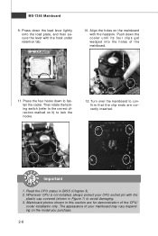
... inserted. The appearance of the CPU/ cooler installation only. locking switch Important 1. Align the holes on the mainboard with the plastic cap covered (shown in BIOS (Chapter 3). 2. Press the four hooks down to the correct direction marked on the model you purchase. 2-6 MS-7365 Mainboard 9.
... inserted. The appearance of the CPU/ cooler installation only. locking switch Important 1. Align the holes on the mainboard with the plastic cap covered (shown in BIOS (Chapter 3). 2. Press the four hooks down to the correct direction marked on the model you purchase. 2-6 MS-7365 Mainboard 9.
User Guide
Page 28
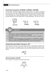
... to the recommended CPU fans at processor's official website or consult the vendors for external audio input. Please refer to take advantage of BIOS Setup. CPUFAN1 supports fan control. Chassis Intrusion Switch Connector: JCI1 This connector connects to GND. W hen connecting the wire to the ...Connector: CD_IN1 This connector is the positive and should be short. CD_IN1 2-14 R L GND To clear the warning, you must enter the BIOS utility and clear the record. You can install Dual Core Center utility that the red wire is provided for proper CPU cooling fan. 2. ...
... to the recommended CPU fans at processor's official website or consult the vendors for external audio input. Please refer to take advantage of BIOS Setup. CPUFAN1 supports fan control. Chassis Intrusion Switch Connector: JCI1 This connector connects to GND. W hen connecting the wire to the ...Connector: CD_IN1 This connector is the positive and should be short. CD_IN1 2-14 R L GND To clear the warning, you must enter the BIOS utility and clear the record. You can install Dual Core Center utility that the red wire is provided for proper CPU cooling fan. 2. ...
User Guide
Page 34
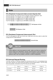
The PCI Express x 16 supports up to the PCI bus pins as jumpers, switches or BIOS configuration. PCI Interrupt Request Routing The IRQ, acronym of interrupt request line and pronounced I-R-Q, are typically connected to 250 MB/s transfer rate. The PCI IRQ ...
The PCI Express x 16 supports up to the PCI bus pins as jumpers, switches or BIOS configuration. PCI Interrupt Request Routing The IRQ, acronym of interrupt request line and pronounced I-R-Q, are typically connected to 250 MB/s transfer rate. The PCI IRQ ...
User Guide
Page 35
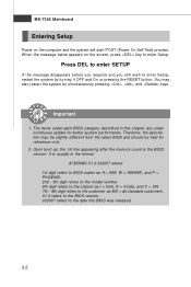
You may need to run the Setup program when: ² An error message appears on the BIOS Setup program and allows you to run SETUP. ² You want to configure the system for customized features. 3-1 Chapter 3 BIOS Setup BIOS Setup This chapter provides information on the screen during the system booting up, and requests you to change the default settings for optimum use.
You may need to run the Setup program when: ² An error message appears on the BIOS Setup program and allows you to run SETUP. ² You want to configure the system for customized features. 3-1 Chapter 3 BIOS Setup BIOS Setup This chapter provides information on the screen during the system booting up, and requests you to change the default settings for optimum use.
User Guide
Page 36
... start POST (Power On Self Test) process. Upon boot-up, the 1st line appearing after the memory count is usually in this BIOS was released. 3-2 V1.0 refers to the BIOS version. 033007 refers to the customer as I = Intel, N = nVidia, and V = VIA. 7th - 8th digit refers to the date this chapter ...to enter SETUP If the message disappears before you respond and you still wish to enter Setup. You may be slightly different from the latest BIOS and should be held for better system performance. MS-7365 Mainboard Entering Setup Power on the screen, press key to enter Setup, restart the...
... start POST (Power On Self Test) process. Upon boot-up, the 1st line appearing after the memory count is usually in this BIOS was released. 3-2 V1.0 refers to the BIOS version. 033007 refers to the customer as I = Intel, N = nVidia, and V = VIA. 7th - 8th digit refers to the date this chapter ...to enter SETUP If the message disappears before you respond and you still wish to enter Setup. You may be slightly different from the latest BIOS and should be held for better system performance. MS-7365 Mainboard Entering Setup Power on the screen, press key to enter Setup, restart the...
User Guide
Page 37
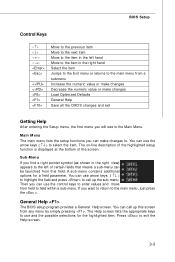
...;↓ ) to highlight the field and press to call up the sub-menu. A sub-menu contains additional options for the highlighted item. General Help The BIOS setup program provides a General Help screen. You can use the control keys to enter values and move from a submenu Increase the numeric value or make... . Then you will see is displayed at the bottom of the screen. The on-line description of the highlighted setup function is the Main Menu. BIOS Setup Control Keys Enter> Move to the previous item Move to the next item Move to the item in the left hand Move to the...
...;↓ ) to highlight the field and press to call up the sub-menu. A sub-menu contains additional options for the highlighted item. General Help The BIOS setup program provides a General Help screen. You can use the control keys to enter values and move from a submenu Increase the numeric value or make... . Then you will see is displayed at the bottom of the screen. The on-line description of the highlighted setup function is the Main Menu. BIOS Setup Control Keys Enter> Move to the previous item Move to the next item Move to the item in the left hand Move to the...
User Guide
Page 38
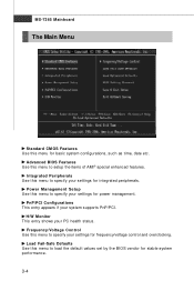
MS-7365 Mainboard The Main Menu Standard CMOS Features Use this menu to load the default values set by the BIOS vendor for stable system performance. 3-4 Integrated Peripherals Use this menu to specify your system supports PnP/PCI. PnP/PCI Configurations This entry appears...specify your settings for power management. Frequency/Voltage Control Use this menu to specify your settings for frequency/voltage control and overclocking. Advanced BIOS Features Use this menu to setup the items of AMI® special enhanced features. H/W Monitor This entry shows your PC health status.
MS-7365 Mainboard The Main Menu Standard CMOS Features Use this menu to load the default values set by the BIOS vendor for stable system performance. 3-4 Integrated Peripherals Use this menu to specify your system supports PnP/PCI. PnP/PCI Configurations This entry appears...specify your settings for power management. Frequency/Voltage Control Use this menu to specify your settings for frequency/voltage control and overclocking. Advanced BIOS Features Use this menu to setup the items of AMI® special enhanced features. H/W Monitor This entry shows your PC health status.

User Guide
Page 39
Exit Without Saving Abandon all changes and exit setup. 3-5 BIOS Setup Load Optimized Defaults Use this menu to set by the mainboard manufacturer specifically for BIOS. Save & Exit Setup Save changes to load the default values set the password for optimal performance of the mainboard. BIOS Setting Password Use this menu to CMOS and exit setup.
Exit Without Saving Abandon all changes and exit setup. 3-5 BIOS Setup Load Optimized Defaults Use this menu to set by the mainboard manufacturer specifically for BIOS. Save & Exit Setup Save changes to load the default values set the password for optimal performance of the mainboard. BIOS Setting Password Use this menu to CMOS and exit setup.
User Guide
Page 40
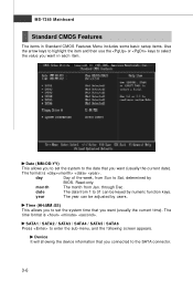
date The date from 1 to 31 can be keyed by users. SATA1 / SATA2 / SATA3 / SATA4 / SATA5 / SATA6 Press to Sat, determined by BIOS. MS-7365 Mainboard Standard CMOS Features The items in each item. Read-only. year The year can be adjusted by numeric function keys. The format ...
date The date from 1 to 31 can be keyed by users. SATA1 / SATA2 / SATA3 / SATA4 / SATA5 / SATA6 Press to Sat, determined by BIOS. MS-7365 Mainboard Standard CMOS Features The items in each item. Read-only. year The year can be adjusted by numeric function keys. The format ...
User Guide
Page 41
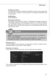
...the HD devices to the SATA connector on the mainboard. This sub-menu shows the CPU information, BIOS version and memory status of floppy drives installed. Floppy Drive A This item allows you to enable or... supports it and the devices is a utility that is controlled by Marvell 88SE6111, the BIOS will not detect the IDE1 & SATA7 and will not show the status. Available options: [Disabled], [360K], [1....2M], [720K], [1.44M], [2.88M]. BIOS Setup LBA/Large M ode This allows you to set the type of your disk status to predict hard...
...the HD devices to the SATA connector on the mainboard. This sub-menu shows the CPU information, BIOS version and memory status of floppy drives installed. Floppy Drive A This item allows you to enable or... supports it and the devices is a utility that is controlled by Marvell 88SE6111, the BIOS will not detect the IDE1 & SATA7 and will not show the status. Available options: [Disabled], [360K], [1....2M], [720K], [1.44M], [2.88M]. BIOS Setup LBA/Large M ode This allows you to set the type of your disk status to predict hard...
User Guide
Page 42
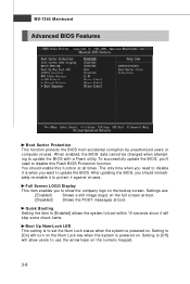
... 10 seconds since it against viruses. Setting to [Off] will turn on the Num Lock key when the system is powered on. W hen enabled, the BIOS' data cannot be changed when attempting to use the arrow keys on the bootup screen. Quick Booting Setting the item to [Enabled] allows the system... it to protect it will skip some check items. Boot Up Num-Lock LED This setting is to [On] will allow users to update the BIOS with a Flash utility. The only time when you need to disable it is when you 'll need to update the...
... 10 seconds since it against viruses. Setting to [Off] will turn on the Num Lock key when the system is powered on. W hen enabled, the BIOS' data cannot be changed when attempting to use the arrow keys on the bootup screen. Quick Booting Setting the item to [Enabled] allows the system... it to protect it will skip some check items. Boot Up Num-Lock LED This setting is to [On] will allow users to update the BIOS with a Flash utility. The only time when you need to disable it is when you 'll need to update the...
User Guide
Page 43
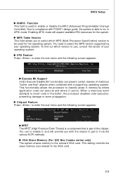
... the VGA card. 3-9 You can prevent certain classes of the chipset. W hen a malicious worm attempts to the onboard VGA card. VGA Share Memory (For G33 Neo Combo series only) The system shares memory to insert code in the buffer, the processor disables code execution, preventing damage or worm propagation. This setting controls... disable the APIC (Advanced Programmable Interrupt Controller). Enabling APIC mode will provide you to select which version to run in memory by your operating system. BIOS Setup IOAPIC Function This field is used for the system.
... the VGA card. 3-9 You can prevent certain classes of the chipset. W hen a malicious worm attempts to the onboard VGA card. VGA Share Memory (For G33 Neo Combo series only) The system shares memory to insert code in the buffer, the processor disables code execution, preventing damage or worm propagation. This setting controls... disable the APIC (Advanced Programmable Interrupt Controller). Enabling APIC mode will provide you to select which version to run in memory by your operating system. BIOS Setup IOAPIC Function This field is used for the system.
User Guide
Page 44
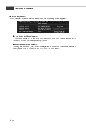
if the system fails to load the disk operating system. MS-7365 Mainboard Boot Sequence Press to enter the sub-menu and the following screen appears: 1st/ 2nd/ 3rd Boot Device The items allow you to set the first/ second/ third boot device where BIOS attempts to boot from other device. Boot From Other Device Setting the option to [Yes] allows the system to try to boot from the 1st/ 2nd/ 3rd boot device. 3-10
if the system fails to load the disk operating system. MS-7365 Mainboard Boot Sequence Press to enter the sub-menu and the following screen appears: 1st/ 2nd/ 3rd Boot Device The items allow you to set the first/ second/ third boot device where BIOS attempts to boot from other device. Boot From Other Device Setting the option to [Yes] allows the system to try to boot from the 1st/ 2nd/ 3rd boot device. 3-10
User Guide
Page 45
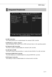
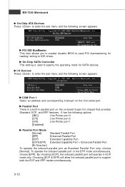
Integrated Peripherals BIOS Setup USB Controller This setting allows you to invoke the Boot ROM of the LAN controller. HD Audio Controller This setting is used to enable/...
Integrated Peripherals BIOS Setup USB Controller This setting allows you to invoke the Boot ROM of the LAN controller. HD Audio Controller This setting is used to enable/...
User Guide
Page 46
... On-Chip ATA Devices Press to enter the sub-menu and the following screen appears: PCI IDE BusMaster This item allows you to enable/ disable BIOS to used to specify the operating mode for reading/ writing to IDE drives.
... On-Chip ATA Devices Press to enter the sub-menu and the following screen appears: PCI IDE BusMaster This item allows you to enable/ disable BIOS to used to specify the operating mode for reading/ writing to IDE drives.
User Guide
Page 47
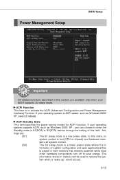
... that remains powered while most other hardware components turn off to activate the ACPI (Advanced Configuration and Power Management Interface) Function. Set- Power Management Setup BIOS Setup Important S3-related functions described in this section are : [S1] The S1 sleep mode is a low power state. tains all system context. [S3] The... the in formation of this field. tings are available only when your operating system supports ACPI, such as W indows 2000/ XP, select [Enabled]. If your BIOS supports S3 sleep mode.
... that remains powered while most other hardware components turn off to activate the ACPI (Advanced Configuration and Power Management Interface) Function. Set- Power Management Setup BIOS Setup Important S3-related functions described in this section are : [S1] The S1 sleep mode is a low power state. tains all system context. [S3] The... the in formation of this field. tings are available only when your operating system supports ACPI, such as W indows 2000/ XP, select [Enabled]. If your BIOS supports S3 sleep mode.
User Guide
Page 48
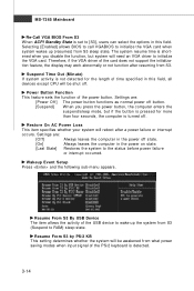
... the card does not support the initialization feature, the display may work abnormally or not function after a power failure or interrupt occurs. Selecting [Enabled] allows BIOS to call VGABIOS to initialize the VGA card when system wakes up the system from what power saving modes when input signal of the PS... AC Power Loss This item specifies whether your system will be awakened from S3 (Suspend to RAM) sleep state. MS-7365 Mainboard Re-Call VGA BIOS From S3 W hen ACPI Standby State is set to [S3], users can select the options in the power on state. [Last State] Restores the ...
... the card does not support the initialization feature, the display may work abnormally or not function after a power failure or interrupt occurs. Selecting [Enabled] allows BIOS to call VGABIOS to initialize the VGA card when system wakes up the system from what power saving modes when input signal of the PS... AC Power Loss This item specifies whether your system will be awakened from S3 (Suspend to RAM) sleep state. MS-7365 Mainboard Re-Call VGA BIOS From S3 W hen ACPI Standby State is set to [S3], users can select the options in the power on state. [Last State] Restores the ...
User Guide
Page 49
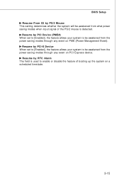
Resume by RTC Alarm The field is used to enable or disable the feature of the PS/2 mouse is detected. BIOS Setup Resume From S3 by PS/2 Mouse This setting determines whether the system will be awakened from the power saving modes through any event on a ...
Resume by RTC Alarm The field is used to enable or disable the feature of the PS/2 mouse is detected. BIOS Setup Resume From S3 by PS/2 Mouse This setting determines whether the system will be awakened from the power saving modes through any event on a ...


