User Guide
Page 5
...478 2-4 Installing the CPU Fan 2-5 Memory 2-7 DDR Module Combination 2-8 Installing DDR Modules 2-8 Power Supply 2-9 ATX 20-Pin Power Connector: CONN1 2-9 ATX 12V Power Connector: ATX12V 2-9 Back Panel 2-10 Mouse Connector 2-10 Keyboard Connector 2-11 USB Connector 2-11 ...Serial Port Connectors: COMA 2-12 v Getting Started 1-1 Mainboard Specifications 1-2 Mainboard Layout 1-4 MSI Special Features 1-5 PC Alert™ 4 1-5 Live BIOS™/Live ...
...478 2-4 Installing the CPU Fan 2-5 Memory 2-7 DDR Module Combination 2-8 Installing DDR Modules 2-8 Power Supply 2-9 ATX 20-Pin Power Connector: CONN1 2-9 ATX 12V Power Connector: ATX12V 2-9 Back Panel 2-10 Mouse Connector 2-10 Keyboard Connector 2-11 USB Connector 2-11 ...Serial Port Connectors: COMA 2-12 v Getting Started 1-1 Mainboard Specifications 1-2 Mainboard Layout 1-4 MSI Special Features 1-5 PC Alert™ 4 1-5 Live BIOS™/Live ...

User Guide
Page 6
BIOS Setup 3-1 Entering Setup 3-2 Control Keys 3-2 Getting Help 3-3 The Main Menu 3-4 Standard CMOS Features 3-6 vi VGA Connector 2-12 RJ-45 LAN Jack 2-13 Audio Port Connectors 2-...
BIOS Setup 3-1 Entering Setup 3-2 Control Keys 3-2 Getting Help 3-3 The Main Menu 3-4 Standard CMOS Features 3-6 vi VGA Connector 2-12 RJ-45 LAN Jack 2-13 Audio Port Connectors 2-...
User Guide
Page 7
or 6-Channel Audio Function A-1 Installing the Audio Driver A-2 Using 4- or 6-Channel Audio Function A-4 Testing the Connected Speakers A-8 Playing KaraOK A-10 Trouble shooting T-1 Glossary ...G-1 vii Advanced BIOS Features 3-8 Advanced Chipset Features 3-12 Integrated Peripherals 3-14 Power Management Setup 3-18 PNP/PCI Configurations 3-22 PC Health Status 3-24 Frequency/Voltage Control 3-25 Load Fail-Safe/Optimized Defaults 3-27 Set Supervisor/User Password 3-28 Appendix: Using 4-
or 6-Channel Audio Function A-1 Installing the Audio Driver A-2 Using 4- or 6-Channel Audio Function A-4 Testing the Connected Speakers A-8 Playing KaraOK A-10 Trouble shooting T-1 Glossary ...G-1 vii Advanced BIOS Features 3-8 Advanced Chipset Features 3-12 Integrated Peripherals 3-14 Power Management Setup 3-18 PNP/PCI Configurations 3-22 PC Health Status 3-24 Frequency/Voltage Control 3-25 Load Fail-Safe/Optimized Defaults 3-27 Set Supervisor/User Password 3-28 Appendix: Using 4-
User Guide
Page 10
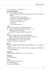
...Suspends to four IDE devices. h Supports ACPI power management. h Provides DMI 2.0, WFM 2.0, WOL, WOR, chassis intrusion, and SMBus for system management. BIOS h 2MB Award BIOS with 360K, 720K, 1.2M, 1.44M and 2.88 Mbytes. - 1 serial port (COMA) and 1 VGA port - 1 parallel port supports SPP/... port supports 2 FDDs with PNP BIOS, ACPI, SMBIOS 2.3, Green and Boot Block. Compliance with AC97 2.2 Spec - Hardware Setup h Can connect up . Compliance with PCI 2.2 and PC99 standard. h Supports Wake-On-LAN and remote wake-up to RAM/Disk 1-3 Dimension h Micro-ATX Form Factor: 24.5 cm (L) ...
...Suspends to four IDE devices. h Supports ACPI power management. h Provides DMI 2.0, WFM 2.0, WOL, WOR, chassis intrusion, and SMBus for system management. BIOS h 2MB Award BIOS with 360K, 720K, 1.2M, 1.44M and 2.88 Mbytes. - 1 serial port (COMA) and 1 VGA port - 1 parallel port supports SPP/... port supports 2 FDDs with PNP BIOS, ACPI, SMBIOS 2.3, Green and Boot Block. Compliance with AC97 2.2 Spec - Hardware Setup h Can connect up . Compliance with PCI 2.2 and PC99 standard. h Supports Wake-On-LAN and remote wake-up to RAM/Disk 1-3 Dimension h Micro-ATX Form Factor: 24.5 cm (L) ...

User Guide
Page 11
AT X Power Supply FDD1 DDR 1 DDR 2 S Y S FA N 1 IDE 2 IDE 1 MS-7005 Micro ATX Mainboard Mainboard Layout Top : mouse Bottom: keyboard BIOS Winbond W83697HF Top : Parallel Port Bottom: COM A VGA Port CPUFAN1 Top : Game port Bottom: Line-Out Line-In Mic AT X 1 2 V SiS 651/650GX T: LAN jack B: USB ports Realtek 8201BL JSP1 JCD1 AGP Slot PCI Slot 1 PCI Slot 2 JUSB2 Codec CNR PCI Slot 3 JAUD1 JUSB1 BATT + SiS 962L J BAT 1 JCI1 JFP1 JFP2 651M-L/650GM-L Series (MS-7005) v1.X Micro ATX Mainboard 1-4
AT X Power Supply FDD1 DDR 1 DDR 2 S Y S FA N 1 IDE 2 IDE 1 MS-7005 Micro ATX Mainboard Mainboard Layout Top : mouse Bottom: keyboard BIOS Winbond W83697HF Top : Parallel Port Bottom: COM A VGA Port CPUFAN1 Top : Game port Bottom: Line-Out Line-In Mic AT X 1 2 V SiS 651/650GX T: LAN jack B: USB ports Realtek 8201BL JSP1 JCD1 AGP Slot PCI Slot 1 PCI Slot 2 JUSB2 Codec CNR PCI Slot 3 JAUD1 JUSB1 BATT + SiS 962L J BAT 1 JCI1 JFP1 JFP2 651M-L/650GM-L Series (MS-7005) v1.X Micro ATX Mainboard 1-4
User Guide
Page 13
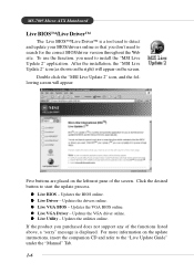
... driver online. MS-7005 Micro ATX Mainboard Live BIOS™/Live Driver™ The Live BIOS™/Live Driver™ is displayed. Click the desired button to the "Live Update Guide" under the "Manual" Tab. 1-6 z Live Driver - Updates the utilities online. Updates the BIOS online. z Live VGA BIOS - If the product you need to install the "MSI Live Update...
... driver online. MS-7005 Micro ATX Mainboard Live BIOS™/Live Driver™ The Live BIOS™/Live Driver™ is displayed. Click the desired button to the "Live Update Guide" under the "Manual" Tab. 1-6 z Live Driver - Updates the utilities online. Updates the BIOS online. z Live VGA BIOS - If the product you need to install the "MSI Live Update...

User Guide
Page 14
... a tool used to a database which contains various possible questions about MSI's products for the BIOS/drivers version, or change the LAN settings right from the dialog box. Provides a link to schedule the search for the BIOS/drivers version you need immediately. Ø View Last Result - Double... click this icon to install the "MSI Live Update 2" application. You can right-click the MSI Live Monitor icon listed below: to inquire. Ø Exit -...
... a tool used to a database which contains various possible questions about MSI's products for the BIOS/drivers version, or change the LAN settings right from the dialog box. Provides a link to schedule the search for the BIOS/drivers version you need immediately. Ø View Last Result - Double... click this icon to install the "MSI Live Update 2" application. You can right-click the MSI Live Monitor icon listed below: to inquire. Ø Exit -...
User Guide
Page 36
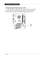
MS-7005 Micro ATX Mainboard Chassis Intrusion Switch Connector: JCI1 This connector is open, the switch will record this status. The system will be short. If the Chassis is connected to 2-pin connector chassis switch. To clear the warning, you must enter the BIOS setting and clear the status. + JCI1 2-22
MS-7005 Micro ATX Mainboard Chassis Intrusion Switch Connector: JCI1 This connector is open, the switch will record this status. The system will be short. If the Chassis is connected to 2-pin connector chassis switch. To clear the warning, you must enter the BIOS setting and clear the status. + JCI1 2-22
User Guide
Page 38
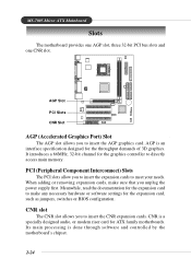
... processing is an interface specification designed for the graphics controller to insert the AGP graphics card. AGP is done through software and controlled by the motherboard's chipset. 2-24 CNR slot The CNR slot allows you to directly access main memory. It introduces a 66MHz, 32-bit channel for the ... you to meet your needs. CNR is a specially designed audio, or modem riser card for the expansion card, such as jumpers, switches or BIOS configuration. MS-7005 Micro ATX Mainboard Slots The motherboard provides one AGP slot, three 32-bit PCI bus slots and one CNR slot.
... processing is an interface specification designed for the graphics controller to insert the AGP graphics card. AGP is done through software and controlled by the motherboard's chipset. 2-24 CNR slot The CNR slot allows you to directly access main memory. It introduces a 66MHz, 32-bit channel for the ... you to meet your needs. CNR is a specially designed audio, or modem riser card for the expansion card, such as jumpers, switches or BIOS configuration. MS-7005 Micro ATX Mainboard Slots The motherboard provides one AGP slot, three 32-bit PCI bus slots and one CNR slot.

User Guide
Page 40
BIOS Setup BIOS Setup This chapter provides information on the screen during the system booting up, and requests you to change the default settings for optimum use. You may need to run the Setup program when: ” An error message appears on the BIOS Setup program and allows you to run SETUP. ” You want to configure the system for customized features. 3-1 BIOS Setup Chapter 3.
BIOS Setup BIOS Setup This chapter provides information on the screen during the system booting up, and requests you to change the default settings for optimum use. You may need to run the Setup program when: ” An error message appears on the BIOS Setup program and allows you to run SETUP. ” You want to configure the system for customized features. 3-1 BIOS Setup Chapter 3.

User Guide
Page 42
... main menu, just press . If you can be launched from this screen from the latest BIOS and should be slightly different from any menu by simply pressing . Therefore, the description may be held for reference only. 3-3 MSI Reminds You... You can call up this field. Main Menu The main menu lists the...
... main menu, just press . If you can be launched from this screen from the latest BIOS and should be slightly different from any menu by simply pressing . Therefore, the description may be held for reference only. 3-3 MSI Reminds You... You can call up this field. Main Menu The main menu lists the...

User Guide
Page 43
...to accept or enter the sub-menu. Integrated Peripherals Use this menu for power management. The Main Menu allows you enter Award® BIOS CMOS Setup Utility, the Main Menu (figure below) will appear on the screen. Standard CMOS Features Use this menu to select from... BIOS Features Use this menu to setup the items of Award® special enhanced features. Power Management Setup Use this menu to specify your settings for basic system configurations, such as time, date etc. PNP/PCI Configurations This entry appears if your PC health status. 3-4 MS-7005 Micro ATX Mainboard...
...to accept or enter the sub-menu. Integrated Peripherals Use this menu for power management. The Main Menu allows you enter Award® BIOS CMOS Setup Utility, the Main Menu (figure below) will appear on the screen. Standard CMOS Features Use this menu to select from... BIOS Features Use this menu to setup the items of Award® special enhanced features. Power Management Setup Use this menu to specify your settings for basic system configurations, such as time, date etc. PNP/PCI Configurations This entry appears if your PC health status. 3-4 MS-7005 Micro ATX Mainboard...

User Guide
Page 44
... the best system performance, but the system stability may be affected. Set User Password Use this menu to load the BIOS values for stable system performance operations. Load Fail-Safe Defaults Use this menu to set Supervisor Password. Save & Exit Setup Save changes to specify your ...settings for frequency/voltage control. Exit Without Saving Abandon all changes and exit setup. 3-5 BIOS Setup Frequency/Voltage Control Use this menu to CMOS and exit setup.
... the best system performance, but the system stability may be affected. Set User Password Use this menu to load the BIOS values for stable system performance operations. Load Fail-Safe Defaults Use this menu to set Supervisor Password. Save & Exit Setup Save changes to specify your ...settings for frequency/voltage control. Exit Without Saving Abandon all changes and exit setup. 3-5 BIOS Setup Frequency/Voltage Control Use this menu to CMOS and exit setup.

User Guide
Page 45
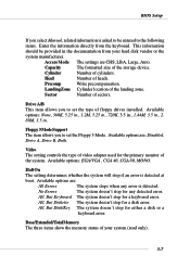
IDE Primary/Secondary Master/Slave Press PgUp/ or PgDn/ to 31 can be adjusted by BIOS. through Dec. Note that the specifications of the week, from Sun to select the value you enter improper information for this category. MS-7005 Micro ATX Mainboard Standard CMOS Features The items in each item. day month date year Day...
IDE Primary/Secondary Master/Slave Press PgUp/ or PgDn/ to 31 can be adjusted by BIOS. through Dec. Note that the specifications of the week, from Sun to select the value you enter improper information for this category. MS-7005 Micro ATX Mainboard Standard CMOS Features The items in each item. day month date year Day...
User Guide
Page 46
... you to set the Floppy 3 Mode. All, But Disk/Key The system doesn't stop for the primary monitor of heads. Head Number of the system. BIOS Setup If you select Manual, related information is asked to be provided in .
... you to set the Floppy 3 Mode. All, But Disk/Key The system doesn't stop for the primary monitor of heads. Head Number of the system. BIOS Setup If you select Manual, related information is asked to be provided in .
User Guide
Page 47
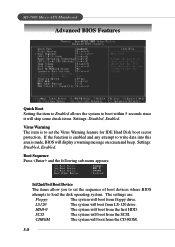
...menu appears: 1st/2nd/3rd Boot Device The items allow you to set the Virus Warning feature for IDE Hard Disk boot sector protection. MS-7005 Micro ATX Mainboard Advanced BIOS Features Quick Boot Setting the item to Enabled allows the system to load the disk operating system. SCSI The system will display a warning... floppy drive. If the function is enabled and any attempt to write data into this area is to set the sequence of boot devices where BIOS attempts to boot within 5 seconds since it will boot from the CD-ROM. 3-8 The settings are: Floppy The system will boot from the ...
...menu appears: 1st/2nd/3rd Boot Device The items allow you to set the Virus Warning feature for IDE Hard Disk boot sector protection. MS-7005 Micro ATX Mainboard Advanced BIOS Features Quick Boot Setting the item to Enabled allows the system to load the disk operating system. SCSI The system will display a warning... floppy drive. If the function is enabled and any attempt to write data into this area is to set the sequence of boot devices where BIOS attempts to boot within 5 seconds since it will boot from the CD-ROM. 3-8 The settings are: Floppy The system will boot from the ...
User Guide
Page 48
...the USB-interface devices, please set USB Keyboard/Mouse Support in SiS OnChip PCI Device of Integrated Peripherals to boot from the fourth HDD. MSI Reminds You... If you to enable or disable the Intel Hyper Threading CPU function. Hyper-Threading Technology This field is used to turn on... drive. USB-HDD The system will boot from the second HDD. Setting to boot from the Network drive. Please disable this sequence. BIOS Setup HDD-1 The system will boot from the USB-interface HDD. USB-CDROM The system will increase the system performance.
...the USB-interface devices, please set USB Keyboard/Mouse Support in SiS OnChip PCI Device of Integrated Peripherals to boot from the fourth HDD. MSI Reminds You... If you to enable or disable the Intel Hyper Threading CPU function. Hyper-Threading Technology This field is used to turn on... drive. USB-HDD The system will boot from the second HDD. Setting to boot from the Network drive. Please disable this sequence. BIOS Setup HDD-1 The system will boot from the USB-interface HDD. USB-CDROM The system will increase the system performance.
User Guide
Page 49
... swap floppy drives A: and B:. MS-7005 Micro ATX Mainboard MSI Reminds You... Seek Floppy Setting to use the arrow keys on . Typematic Delay (Msec) This item allows you to set the Num Lock status when the system is used to Enabled will make BIOS seek floppy drive A: before booting the... following platform Components: *CPU: An Intel® Pentium® 4 Processor with HT Technology; *Chipset: A chipset that supports HT Technology; *BIOS: A BIOS that supports HT Technology and has it enabled; *OS: Only Microsoft® Windows 2000 and XP can support HT technology. CPU L2 Cache ECC...
... swap floppy drives A: and B:. MS-7005 Micro ATX Mainboard MSI Reminds You... Seek Floppy Setting to use the arrow keys on . Typematic Delay (Msec) This item allows you to set the Num Lock status when the system is used to Enabled will make BIOS seek floppy drive A: before booting the... following platform Components: *CPU: An Intel® Pentium® 4 Processor with HT Technology; *Chipset: A chipset that supports HT Technology; *BIOS: A BIOS that supports HT Technology and has it enabled; *OS: Only Microsoft® Windows 2000 and XP can support HT technology. CPU L2 Cache ECC...
User Guide
Page 50
... to run in APIC mode. Settings: Enabled, Disabled. MPS Table Version This field allows you to select which version to use, consult the vendor of BIOS password protection that is powered on or when end users try to enable or disable the APIC (Advanced Programmable Interrupt Controller). Settings: 1.4, 1.1. Capability This allows... resources for the hard disks. To find out which MPS (Multi-Processor Specification) version to be used to run Setup. Settings: Enabled and Disabled. 3-11 BIOS Setup Security Option This specifies the type of your operating system.
... to run in APIC mode. Settings: Enabled, Disabled. MPS Table Version This field allows you to select which version to use, consult the vendor of BIOS password protection that is powered on or when end users try to enable or disable the APIC (Advanced Programmable Interrupt Controller). Settings: 1.4, 1.1. Capability This allows... resources for the hard disks. To find out which MPS (Multi-Processor Specification) version to be used to run Setup. Settings: Enabled and Disabled. 3-11 BIOS Setup Security Option This specifies the type of your operating system.
User Guide
Page 51
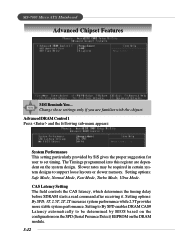
... if you are dependent on the DRAM module. 3-12 The Timings programmed into this register are familiar with the chipset. MS-7005 Micro ATX Mainboard Advanced Chipset Features MSI Reminds You... Setting options: Safe Mode, Normal Mode, Fast Mode, Turbo Mode, Ultra Mode. CAS Latency Setting The ...a read command after receiving it. Advanced DRAM Control 1 Press and the following sub-menu appears: System Performance This setting particularly provided by BIOS based on the configurations on the SPD (Serial Presence Detect) EEPROM on the system design. Setting options: By SPD, 3T, 2.5T, ...
... if you are dependent on the DRAM module. 3-12 The Timings programmed into this register are familiar with the chipset. MS-7005 Micro ATX Mainboard Advanced Chipset Features MSI Reminds You... Setting options: Safe Mode, Normal Mode, Fast Mode, Turbo Mode, Ultra Mode. CAS Latency Setting The ...a read command after receiving it. Advanced DRAM Control 1 Press and the following sub-menu appears: System Performance This setting particularly provided by BIOS based on the configurations on the SPD (Serial Presence Detect) EEPROM on the system design. Setting options: By SPD, 3T, 2.5T, ...


