User Guide
Page 2
... be required to radio communications. Operation of the FCC rules. VOIR LA NOTICE D'INSTALLATION AVANT DE RACCORDER AU RESEAU. Notice 2 Shielded interface cables and A.C. Micro-Star International MS-7005 Tested to operate the equipment. These limits are designed to provide reasonable protection against harmful interference when the equipment is likely to cause harmful...
... be required to radio communications. Operation of the FCC rules. VOIR LA NOTICE D'INSTALLATION AVANT DE RACCORDER AU RESEAU. Notice 2 Shielded interface cables and A.C. Micro-Star International MS-7005 Tested to operate the equipment. These limits are designed to provide reasonable protection against harmful interference when the equipment is likely to cause harmful...

User Guide
Page 8
Hardware Setup Getting Started Thank you for high-speed data transmission. With all these special designs, the 651M-L/650GM-L series delivers a high performance and professional desktop platform solution. 1-1 The 651M-L/650GM-L series is based on SiS® 651/650GX (702 pin BGA) & SiS® 962L MuTIOL Media I/O (371 BGA) chipsets and provides 6 USB 2.0 ports for purchasing 651M-L/650GM-L Series (MS-7005) v1.X Micro ATX mainboard.
Hardware Setup Getting Started Thank you for high-speed data transmission. With all these special designs, the 651M-L/650GM-L series delivers a high performance and professional desktop platform solution. 1-1 The 651M-L/650GM-L series is based on SiS® 651/650GX (702 pin BGA) & SiS® 962L MuTIOL Media I/O (371 BGA) chipsets and provides 6 USB 2.0 ports for purchasing 651M-L/650GM-L Series (MS-7005) v1.X Micro ATX mainboard.
User Guide
Page 9
...) ; Integrated multi-threaded I/O link ensures concurrency of up/down stream data transfer with fast write transaction - On-Board IDE h Dual IDE controllers integrated in SiS962L. MS-7005 Micro ATX Mainboard Mainboard Specifications CPU h Socket 478 for P4 processors (Willamette 478 / Northwood 478 / Celeron 478) at 400 MHz/ 533 MHz h Supports up to 2GB memory...
...) ; Integrated multi-threaded I/O link ensures concurrency of up/down stream data transfer with fast write transaction - On-Board IDE h Dual IDE controllers integrated in SiS962L. MS-7005 Micro ATX Mainboard Mainboard Specifications CPU h Socket 478 for P4 processors (Willamette 478 / Northwood 478 / Celeron 478) at 400 MHz/ 533 MHz h Supports up to 2GB memory...

User Guide
Page 11
AT X Power Supply FDD1 DDR 1 DDR 2 S Y S FA N 1 IDE 2 IDE 1 MS-7005 Micro ATX Mainboard Mainboard Layout Top : mouse Bottom: keyboard BIOS Winbond W83697HF Top : Parallel Port Bottom: COM A VGA Port CPUFAN1 Top : Game port Bottom: Line-Out Line-In Mic AT X 1 2 V SiS 651/650GX T: LAN jack B: USB ports Realtek 8201BL JSP1 JCD1 AGP Slot PCI Slot 1 PCI Slot 2 JUSB2 Codec CNR PCI Slot 3 JAUD1 JUSB1 BATT + SiS 962L J BAT 1 JCI1 JFP1 JFP2 651M-L/650GM-L Series (MS-7005) v1.X Micro ATX Mainboard 1-4
AT X Power Supply FDD1 DDR 1 DDR 2 S Y S FA N 1 IDE 2 IDE 1 MS-7005 Micro ATX Mainboard Mainboard Layout Top : mouse Bottom: keyboard BIOS Winbond W83697HF Top : Parallel Port Bottom: COM A VGA Port CPUFAN1 Top : Game port Bottom: Line-Out Line-In Mic AT X 1 2 V SiS 651/650GX T: LAN jack B: USB ports Realtek 8201BL JSP1 JCD1 AGP Slot PCI Slot 1 PCI Slot 2 JUSB2 Codec CNR PCI Slot 3 JAUD1 JUSB1 BATT + SiS 962L J BAT 1 JCI1 JFP1 JFP2 651M-L/650GM-L Series (MS-7005) v1.X Micro ATX Mainboard 1-4
User Guide
Page 13
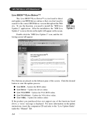
...above, a "sorry" message is a tool used to detect and update your BIOS/drivers online so that you don't need to install the "MSI Live Update 2" application. Updates the VGA BIOS online. Updates the utilities online. If the product you need to search for the correct BIOS/... the Web site. Double click the "MSI Live Update 2" icon, and the following screen will appear on the update instructions, insert the companion CD and refer to the "Live Update Guide" under the "Manual" Tab. 1-6 Updates the BIOS online. MS-7005 Micro ATX Mainboard Live BIOS™/Live Driver™...
...above, a "sorry" message is a tool used to detect and update your BIOS/drivers online so that you don't need to install the "MSI Live Update 2" application. Updates the VGA BIOS online. Updates the utilities online. If the product you need to search for the correct BIOS/... the Web site. Double click the "MSI Live Update 2" icon, and the following screen will appear on the update instructions, insert the companion CD and refer to the "Live Update Guide" under the "Manual" Tab. 1-6 Updates the BIOS online. MS-7005 Micro ATX Mainboard Live BIOS™/Live Driver™...
User Guide
Page 18
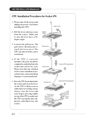
... 478 1. Sliding Plate Open Lever 90 degree Gold arrow Gold arrow Correct CPU placement O Gold arrow Incorrect CPU placement X Press down firmly into the socket. MS-7005 Micro ATX Mainboard CPU Installation Procedures for the gold arrow. The gold arrow should be seen. If the CPU is properly and completely embedded into the socket...
... 478 1. Sliding Plate Open Lever 90 degree Gold arrow Gold arrow Correct CPU placement O Gold arrow Incorrect CPU placement X Press down firmly into the socket. MS-7005 Micro ATX Mainboard CPU Installation Procedures for the gold arrow. The gold arrow should be seen. If the CPU is properly and completely embedded into the socket...
User Guide
Page 20
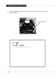
MS-7005 Micro ATX Mainboard 5. fan power cable NOTES 2-6 tor on the board. Connect the fan power cable from the mounted fan to the 3-pin fan power connec-
MS-7005 Micro ATX Mainboard 5. fan power cable NOTES 2-6 tor on the board. Connect the fan power cable from the mounted fan to the 3-pin fan power connec-
User Guide
Page 22
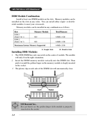
... install either single- The DDR DIMM has only one DIMM module on the slots in the right orientation. 2. The module will automatically close. Volt Notch MSI Reminds You... Then push it in until the golden finger on the center of the DIMM slot will only fit in any combination as follows... the memory module is properly inserted in the socket. 3. You can barely see the golden finger if the module is deeply inserted in the socket. 2-8 MS-7005 Micro ATX Mainboard DDR Module Combination Install at each side of module.
... install either single- The DDR DIMM has only one DIMM module on the slots in the right orientation. 2. The module will automatically close. Volt Notch MSI Reminds You... Then push it in until the golden finger on the center of the DIMM slot will only fit in any combination as follows... the memory module is properly inserted in the socket. 3. You can barely see the golden finger if the module is deeply inserted in the socket. 2-8 MS-7005 Micro ATX Mainboard DDR Module Combination Install at each side of module.
User Guide
Page 24
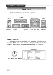
... 5 Mouse Clock 6 NC DESCRIPTION Mouse DATA No connection Ground +5V Mouse clock No connection 2-10 You can plug a PS/2® mouse directly into this connector. MS-7005 Micro ATX Mainboard Back Panel The back panel provides the following connectors: Mouse Parallel Midi/Joystick LAN Keyboard COMA VGA Port L-out L-in MIC USB Ports Mouse...
... 5 Mouse Clock 6 NC DESCRIPTION Mouse DATA No connection Ground +5V Mouse clock No connection 2-10 You can plug a PS/2® mouse directly into this connector. MS-7005 Micro ATX Mainboard Back Panel The back panel provides the following connectors: Mouse Parallel Midi/Joystick LAN Keyboard COMA VGA Port L-out L-in MIC USB Ports Mouse...
User Guide
Page 26
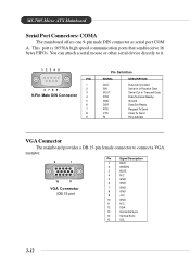
MS-7005 Micro ATX Mainboard Serial Port Connectors: COMA The mainboard offers one 9-pin male DIN connector as serial port COM A. You can attach a serial mouse or other serial ...
MS-7005 Micro ATX Mainboard Serial Port Connectors: COMA The mainboard offers one 9-pin male DIN connector as serial port COM A. You can attach a serial mouse or other serial ...
User Guide
Page 28
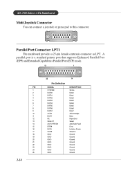
... 18 GND Ground 19 GND Ground 20 GND Ground 21 GND Ground 22 GND Ground 23 GND Ground 24 GND Ground 25 GND Ground 2-14 MS-7005 Micro ATX Mainboard Midi/Joystick Connector You can connect a joystick or game pad to this connector.
... 18 GND Ground 19 GND Ground 20 GND Ground 21 GND Ground 22 GND Ground 23 GND Ground 24 GND Ground 25 GND Ground 2-14 MS-7005 Micro ATX Mainboard Midi/Joystick Connector You can connect a joystick or game pad to this connector.
User Guide
Page 30
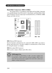
...you must configure second hard drive to the hard disk documentation supplied by setting its jumper. You can connect a Master and a Slave drive. MSI Reminds You... You must configure the second drive to IDE1. IDE1 can connect up to four hard disk drives, CD-ROM, 120MB Floppy and... mode by hard disk vendors for jumper setting instructions. 2-16 IDE2 (Secondary IDE Connector) IDE2 can also connect a Master and a Slave drive. MS-7005 Micro ATX Mainboard Hard Disk Connectors: IDE1 & IDE2 The mainboard has a 32-bit Enhanced PCI IDE and Ultra DMA 33/66/100/ 133 controller that provides...
...you must configure second hard drive to the hard disk documentation supplied by setting its jumper. You can connect a Master and a Slave drive. MSI Reminds You... You must configure the second drive to IDE1. IDE1 can connect up to four hard disk drives, CD-ROM, 120MB Floppy and... mode by hard disk vendors for jumper setting instructions. 2-16 IDE2 (Secondary IDE Connector) IDE2 can also connect a Master and a Slave drive. MS-7005 Micro ATX Mainboard Hard Disk Connectors: IDE1 & IDE2 The mainboard has a 32-bit Enhanced PCI IDE and Ultra DMA 33/66/100/ 133 controller that provides...
User Guide
Page 32
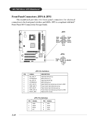
...-up Power Switch low reference pull-down to the front panel switches and LEDs. JFP1 is compliant with Intel® Front Panel I/O Connectivity Design Guide. MS-7005 Micro ATX Mainboard Front Panel Connectors: JFP1 & JFP2 The mainboard provides two front panel connectors for electrical connection to GND Reserved.
...-up Power Switch low reference pull-down to the front panel switches and LEDs. JFP1 is compliant with Intel® Front Panel I/O Connectivity Design Guide. MS-7005 Micro ATX Mainboard Front Panel Connectors: JFP1 & JFP2 The mainboard provides two front panel connectors for electrical connection to GND Reserved.
User Guide
Page 34
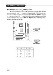
MS-7005 Micro ATX Mainboard Front USB Connectors: JUSB1/JUSB2 The mainboard provides two USB 2.0 pin headers JUSB1 & JUSB2 that are compliant with Intel® I/O Connectivity Design Guide. USB 2.0 ...
MS-7005 Micro ATX Mainboard Front USB Connectors: JUSB1/JUSB2 The mainboard provides two USB 2.0 pin headers JUSB1 & JUSB2 that are compliant with Intel® I/O Connectivity Design Guide. USB 2.0 ...
User Guide
Page 36
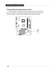
If the Chassis is connected to 2-pin connector chassis switch. MS-7005 Micro ATX Mainboard Chassis Intrusion Switch Connector: JCI1 This connector is open, the switch will record this status. To clear the warning, you must enter the BIOS setting and clear the status. + JCI1 2-22 The system will be short.
If the Chassis is connected to 2-pin connector chassis switch. MS-7005 Micro ATX Mainboard Chassis Intrusion Switch Connector: JCI1 This connector is open, the switch will record this status. To clear the warning, you must enter the BIOS setting and clear the status. + JCI1 2-22 The system will be short.
User Guide
Page 38
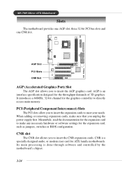
...Its main processing is a specially designed audio, or modem riser card for ATX family motherboards. PCI (Peripheral Component Interconnect) Slots The PCI slots allow you unplug the power supply first. MS-7005 Micro ATX Mainboard Slots The motherboard provides one AGP slot, three 32-bit PCI bus slots and one CNR...that you to insert the expansion cards to insert the AGP graphics card. CNR is done through software and controlled by the motherboard's chipset. 2-24 AGP is an interface specification designed for the graphics controller to insert the CNR expansion cards. AGP Slot...
...Its main processing is a specially designed audio, or modem riser card for ATX family motherboards. PCI (Peripheral Component Interconnect) Slots The PCI slots allow you unplug the power supply first. MS-7005 Micro ATX Mainboard Slots The motherboard provides one AGP slot, three 32-bit PCI bus slots and one CNR...that you to insert the expansion cards to insert the AGP graphics card. CNR is done through software and controlled by the motherboard's chipset. 2-24 AGP is an interface specification designed for the graphics controller to insert the CNR expansion cards. AGP Slot...
User Guide
Page 41
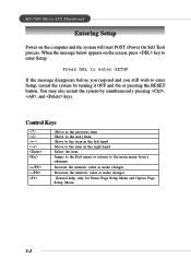
... to enter SETUP If the message disappears before you respond and you still wish to enter Setup, restart the system by simultaneously pressing , , and keys. MS-7005 Micro ATX Mainboard Entering Setup Power on the screen, press key to enter Setup. You may also restart the system by turning it OFF and On or...
... to enter SETUP If the message disappears before you respond and you still wish to enter Setup, restart the system by simultaneously pressing , , and keys. MS-7005 Micro ATX Mainboard Entering Setup Power on the screen, press key to enter Setup. You may also restart the system by turning it OFF and On or...

User Guide
Page 43
... the sub-menu. PNP/PCI Configurations This entry appears if your PC health status. 3-4 PC Health Status This entry shows your system supports PnP/PCI. MS-7005 Micro ATX Mainboard The Main Menu Once you to specify your system's performance. The Main Menu allows you enter Award® BIOS CMOS Setup Utility, the Main...
... the sub-menu. PNP/PCI Configurations This entry appears if your PC health status. 3-4 PC Health Status This entry shows your system supports PnP/PCI. MS-7005 Micro ATX Mainboard The Main Menu Once you to specify your system's performance. The Main Menu allows you enter Award® BIOS CMOS Setup Utility, the Main...

User Guide
Page 45
... can be keyed by numeric function keys. If your hard disk drive type is not matched or listed, you enter improper information for this category. MS-7005 Micro ATX Mainboard Standard CMOS Features The items in each item. Time The time format is . through Dec. IDE Primary/Secondary Master/Slave Press PgUp/ or PgDn...
... can be keyed by numeric function keys. If your hard disk drive type is not matched or listed, you enter improper information for this category. MS-7005 Micro ATX Mainboard Standard CMOS Features The items in each item. Time The time format is . through Dec. IDE Primary/Secondary Master/Slave Press PgUp/ or PgDn...
User Guide
Page 47
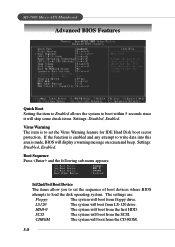
... SCSI. Boot Sequence Press and the following sub-menu appears: 1st/2nd/3rd Boot Device The items allow you to load the disk operating system. MS-7005 Micro ATX Mainboard Advanced BIOS Features Quick Boot Setting the item to Enabled allows the system to write data into this area is made, BIOS will display...
... SCSI. Boot Sequence Press and the following sub-menu appears: 1st/2nd/3rd Boot Device The items allow you to load the disk operating system. MS-7005 Micro ATX Mainboard Advanced BIOS Features Quick Boot Setting the item to Enabled allows the system to write data into this area is made, BIOS will display...


