User Guide
Page 5
...Mainboard Specifications 1-2 Mainboard Layout 1-4 MSI Special Features 1-5 PC Alert™ 4 1-5 Live BIOS™/Live Driver 1-6 Live Monitor 1-7 Chapter 2. CONTENTS FCC-B Radio Frequency Interference Statement ii Copyright Notice iii Revision History iii Technical Support iii Safety Instructions iv Chapter ... 2-4 Installing the CPU Fan 2-5 Memory 2-7 DDR Module Combination 2-8 Installing DDR Modules 2-8 Power Supply 2-9 ATX 20-Pin Power Connector: CONN1 2-9 ATX 12V Power Connector: ATX12V 2-9 Back Panel 2-10 Mouse Connector 2-10 Keyboard Connector 2-11 USB Connector 2-11...
...Mainboard Specifications 1-2 Mainboard Layout 1-4 MSI Special Features 1-5 PC Alert™ 4 1-5 Live BIOS™/Live Driver 1-6 Live Monitor 1-7 Chapter 2. CONTENTS FCC-B Radio Frequency Interference Statement ii Copyright Notice iii Revision History iii Technical Support iii Safety Instructions iv Chapter ... 2-4 Installing the CPU Fan 2-5 Memory 2-7 DDR Module Combination 2-8 Installing DDR Modules 2-8 Power Supply 2-9 ATX 20-Pin Power Connector: CONN1 2-9 ATX 12V Power Connector: ATX12V 2-9 Back Panel 2-10 Mouse Connector 2-10 Keyboard Connector 2-11 USB Connector 2-11...
User Guide
Page 9
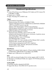
... USB 2.0/1.1 host controller and Fast Ethernet MAC controller - Integrated PCI to 3.06GHz. MS-7005 Micro ATX Mainboard Mainboard Specifications CPU h Socket 478 for P4 processors (Willamette 478 / Northwood 478 / Celeron 478) at 400 MHz/ 533 MHz h Supports up to LPCC bridge Main Memory h Supports two memory banks using two 184-pin unbuffered DDR 200/266 (for...
... USB 2.0/1.1 host controller and Fast Ethernet MAC controller - Integrated PCI to 3.06GHz. MS-7005 Micro ATX Mainboard Mainboard Specifications CPU h Socket 478 for P4 processors (Willamette 478 / Northwood 478 / Celeron 478) at 400 MHz/ 533 MHz h Supports up to LPCC bridge Main Memory h Supports two memory banks using two 184-pin unbuffered DDR 200/266 (for...
User Guide
Page 10
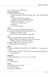
... PC2001 audio performance requirement LAN h SiS 962L integrated MAC + Realtek 8201BL PHY - Dimension h Micro-ATX Form Factor: 24.5 cm (L) x 20.0 cm (W). On-Board Peripherals h On-Board Peripherals include: - 1 floppy port supports 2 FDDs with PNP BIOS, ACPI, SMBIOS 2.3, Green and Boot Block. Others h Live BIOS...system management. BIOS h 2MB Award BIOS with 360K, 720K, 1.2M, 1.44M and 2.88 Mbytes. - 1 serial port (COMA) and 1 VGA port - 1 parallel port supports SPP/EPP/ECP mode - 6 USB 2.0/1.1 ports (Rear * 2 / Front * 4) - 1 Line-In/Line-Out/Mic-In port - 1 game port - 1 RJ...
... PC2001 audio performance requirement LAN h SiS 962L integrated MAC + Realtek 8201BL PHY - Dimension h Micro-ATX Form Factor: 24.5 cm (L) x 20.0 cm (W). On-Board Peripherals h On-Board Peripherals include: - 1 floppy port supports 2 FDDs with PNP BIOS, ACPI, SMBIOS 2.3, Green and Boot Block. Others h Live BIOS...system management. BIOS h 2MB Award BIOS with 360K, 720K, 1.2M, 1.44M and 2.88 Mbytes. - 1 serial port (COMA) and 1 VGA port - 1 parallel port supports SPP/EPP/ECP mode - 6 USB 2.0/1.1 ports (Rear * 2 / Front * 4) - 1 Line-In/Line-Out/Mic-In port - 1 game port - 1 RJ...
User Guide
Page 13
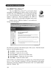
... drivers online. If the product you purchased does not support any of the screen. Updates the utilities online. z Live VGA BIOS - z Live VGA Driver - MS-7005 Micro ATX Mainboard Live BIOS™/Live Driver™ The Live BIOS™/Live Driver™ is displayed. Double click the "MSI Live Update 2" icon, and the following screen will...
... drivers online. If the product you purchased does not support any of the screen. Updates the utilities online. z Live VGA BIOS - z Live VGA Driver - MS-7005 Micro ATX Mainboard Live BIOS™/Live Driver™ The Live BIOS™/Live Driver™ is displayed. Double click the "MSI Live Update 2" icon, and the following screen will...

User Guide
Page 17
...on the top to purchase and install them before turning on the computer. Replacing the CPU While replacing the CPU, always turn off the ATX power supply or unplug the power supply's power cord from grounded outlet first to protect the CPU from overheating. The mainboard uses a ... x Core/Bus ratio = 100MHz x 17 = 1.7GHz Memory Speed/CPU FSB Support Matrix Memory FSB DDR 266 400 MHz OK 533 MHz OK DDR 333 OK OK MSI Reminds You... Hardware Setup Central Processing Unit: CPU The mainboard supports Intel® Pentium® 4 Willamette, Celeron, Northwood processor in the 478 pin...
...on the top to purchase and install them before turning on the computer. Replacing the CPU While replacing the CPU, always turn off the ATX power supply or unplug the power supply's power cord from grounded outlet first to protect the CPU from overheating. The mainboard uses a ... x Core/Bus ratio = 100MHz x 17 = 1.7GHz Memory Speed/CPU FSB Support Matrix Memory FSB DDR 266 400 MHz OK 533 MHz OK DDR 333 OK OK MSI Reminds You... Hardware Setup Central Processing Unit: CPU The mainboard supports Intel® Pentium® 4 Willamette, Celeron, Northwood processor in the 478 pin...

User Guide
Page 21
Hardware Setup Memory The mainboard provides two 184-pin unbuffered DDR200/DDR266/ DDR333 DDR SDRAM, and supports the memory size up to 3.3 volts used in SDR SDRAM, and requires 184-pin DIMM modules rather than 168-pin DIMM modules used by transferring data twice per cycle. It uses 2.5 volts as opposed to 2GB. To operate properly, at least one DIMM module must be installed. + DDR DIMM Slots (DDR 1~2) Introduction to DDR SDRAM DDR (Double Data Rate) SDRAM is similar to conventional SDRAM, but doubles the rate by SDR SDRAM. 2-7
Hardware Setup Memory The mainboard provides two 184-pin unbuffered DDR200/DDR266/ DDR333 DDR SDRAM, and supports the memory size up to 3.3 volts used in SDR SDRAM, and requires 184-pin DIMM modules rather than 168-pin DIMM modules used by transferring data twice per cycle. It uses 2.5 volts as opposed to 2GB. To operate properly, at least one DIMM module must be installed. + DDR DIMM Slots (DDR 1~2) Introduction to DDR SDRAM DDR (Double Data Rate) SDRAM is similar to conventional SDRAM, but doubles the rate by SDR SDRAM. 2-7
User Guide
Page 22
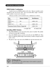
... finger if the module is deeply inserted in any order. You can be installed in the socket. 3. Volt Notch MSI Reminds You... MS-7005 Micro ATX Mainboard DDR Module Combination Install at each side of module. Insert the DIMM memory module vertically into the DIMM slot. ... follows: Slot DDR 1 (Bank 0 & 1) DDR 2 (Bank 2 & 3) Memory Module S/D S/D Total Memory 64MB~1GB 64MB~1GB Maximum System Memory Supported 64MB~2GB Installing DDR Modules S: Single Side D: Double Side 1. The DDR DIMM has only one DIMM module on the slots in the right orientation. 2. ...
... finger if the module is deeply inserted in any order. You can be installed in the socket. 3. Volt Notch MSI Reminds You... MS-7005 Micro ATX Mainboard DDR Module Combination Install at each side of module. Insert the DIMM memory module vertically into the DIMM slot. ... follows: Slot DDR 1 (Bank 0 & 1) DDR 2 (Bank 2 & 3) Memory Module S/D S/D Total Memory 64MB~1GB 64MB~1GB Maximum System Memory Supported 64MB~2GB Installing DDR Modules S: Single Side D: Double Side 1. The DDR DIMM has only one DIMM module on the slots in the right orientation. 2. ...
User Guide
Page 23
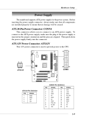
... supply, make sure that all components are aligned. Then push down the power supply firmly into the connector. ATX 20-Pin Power Connector: CONN1 This connector allows you to connect to the CPU. 11 1 42 31 ATX12V 20 10 CONN1 + ATX12V Pin Definition PIN ... 5V 20 5V 2-9 Before inserting the power supply connector, always make sure the plug of the power supply is used to provide power to an ATX power supply. Hardware Setup Power Supply The mainboard supports ATX power supply for the power system.
... supply, make sure that all components are aligned. Then push down the power supply firmly into the connector. ATX 20-Pin Power Connector: CONN1 This connector allows you to connect to the CPU. 11 1 42 31 ATX12V 20 10 CONN1 + ATX12V Pin Definition PIN ... 5V 20 5V 2-9 Before inserting the power supply connector, always make sure the plug of the power supply is used to provide power to an ATX power supply. Hardware Setup Power Supply The mainboard supports ATX power supply for the power system.

User Guide
Page 27
... audio operation, please refer to the LAN jack. Line In is a connector for microphones. 1/8" Stereo Audio Connectors Line Out Line In MIC MSI Reminds You... You can turn rear audio connectors from 2-channel to Local Area Network (LAN). Mic is used for external CD player, Tape ...Differential Pair Receive Differential Pair Not Used Not Used Receive Differential Pair Not Used Not Used Audio Port Connectors Line Out is provided to offer support for 6-channel audio operation and can connect a network cable to Appendix. For advanced audio application, Realtek ALC 655 is a connector for...
... audio operation, please refer to the LAN jack. Line In is a connector for microphones. 1/8" Stereo Audio Connectors Line Out Line In MIC MSI Reminds You... You can turn rear audio connectors from 2-channel to Local Area Network (LAN). Mic is used for external CD player, Tape ...Differential Pair Receive Differential Pair Not Used Not Used Receive Differential Pair Not Used Not Used Audio Port Connectors Line Out is provided to offer support for 6-channel audio operation and can connect a network cable to Appendix. For advanced audio application, Realtek ALC 655 is a connector for...
User Guide
Page 28
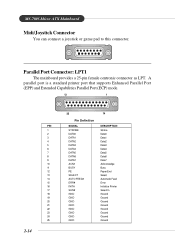
MS-7005 Micro ATX Mainboard Midi/Joystick Connector You can connect a joystick or game pad to this connector. Parallel Port Connector: LPT1 The mainboard provides a 25-pin female centronic connector as LPT. A parallel port is a standard printer port that supports Enhanced Parallel Port (EPP) and Extended Capabilities Parallel Port (ECP) mode. 13 1 25 14 Pin Definition...
MS-7005 Micro ATX Mainboard Midi/Joystick Connector You can connect a joystick or game pad to this connector. Parallel Port Connector: LPT1 The mainboard provides a 25-pin female centronic connector as LPT. A parallel port is a standard printer port that supports Enhanced Parallel Port (EPP) and Extended Capabilities Parallel Port (ECP) mode. 13 1 25 14 Pin Definition...
User Guide
Page 29
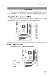
FDD1 + CD-In Connector: JCD1 The connector is for CD-ROM audio connector. L GND R JCD1 + 2-15 Floppy Disk Drive Connector: FDD1 The mainboard provides a standard floppy disk drive connector that supports 360K, 720K, 1.2M, 1.44M and 2.88M floppy disk types. Hardware Setup Connectors The mainboard provides connectors to connect to FDD, IDE HDD, case, LAN, USB Ports, IR module and CPU/System/Power Supply FAN.
FDD1 + CD-In Connector: JCD1 The connector is for CD-ROM audio connector. L GND R JCD1 + 2-15 Floppy Disk Drive Connector: FDD1 The mainboard provides a standard floppy disk drive connector that supports 360K, 720K, 1.2M, 1.44M and 2.88M floppy disk types. Hardware Setup Connectors The mainboard provides connectors to connect to FDD, IDE HDD, case, LAN, USB Ports, IR module and CPU/System/Power Supply FAN.

User Guide
Page 31
...System Hardware Monitor chipset on-board, you must use a specially designed fan with +12V. GND +12V SENSOR CPUFAN1 GND +12V SENSOR SYSFAN1 + MSI Reminds You... 1. Always consult the vendors for proper CPU cooling fan. 2. Hardware Setup Fan Power Connectors: CPUFAN1/SYSFAN1 The CPUFAN1 (processor fan)... and SYSFAN1 (system fan) support system cooling fan with speed sensor to take note that will automatically control the CPU fan speed according to the actual CPU temperature. 2-17...
...System Hardware Monitor chipset on-board, you must use a specially designed fan with +12V. GND +12V SENSOR CPUFAN1 GND +12V SENSOR SYSFAN1 + MSI Reminds You... 1. Always consult the vendors for proper CPU cooling fan. 2. Hardware Setup Fan Power Connectors: CPUFAN1/SYSFAN1 The CPUFAN1 (processor fan)... and SYSFAN1 (system fan) support system cooling fan with speed sensor to take note that will automatically control the CPU fan speed according to the actual CPU temperature. 2-17...

User Guide
Page 35
Connected to an external SPDIF Bracket for digital audio transmission. JSP1 Pin Definition PIN SIGNAL 1 VCCS 2 SPDIF0 3 GND + 3 1 JSP1 The JSP1 supports SPDIF output only and can be connected to JSP1 SPDIF Bracket 2-21 Hardware Setup SPDIF Connector: JSP1 (Optional) The connector is used to connect SPDIF (Sony & Philips Digital Interconnect Format) interface for digital audio transmission.
Connected to an external SPDIF Bracket for digital audio transmission. JSP1 Pin Definition PIN SIGNAL 1 VCCS 2 SPDIF0 3 GND + 3 1 JSP1 The JSP1 supports SPDIF output only and can be connected to JSP1 SPDIF Bracket 2-21 Hardware Setup SPDIF Connector: JSP1 (Optional) The connector is used to connect SPDIF (Sony & Philips Digital Interconnect Format) interface for digital audio transmission.

User Guide
Page 43
PC Health Status This entry shows your system supports PnP/PCI. MS-7005 Micro ATX Mainboard The Main Menu Once you to accept or enter the sub-menu. Advanced BIOS Features Use this menu to specify your settings for power ...
PC Health Status This entry shows your system supports PnP/PCI. MS-7005 Micro ATX Mainboard The Main Menu Once you to accept or enter the sub-menu. Advanced BIOS Features Use this menu to specify your settings for power ...
User Guide
Page 46
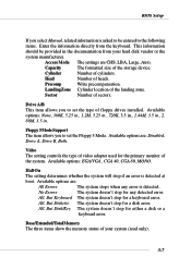
.... Drive A/B This item allows you to set the type of the landing zone. All, But Keyboard The system doesn't stop for a keyboard error. Floppy 3 Mode Support The item allows you to set the Floppy 3 Mode. Head Number of sectors. This information should be entered to the following items. Enter the information...
.... Drive A/B This item allows you to set the type of the landing zone. All, But Keyboard The system doesn't stop for a keyboard error. Floppy 3 Mode Support The item allows you to set the Floppy 3 Mode. Head Number of sectors. This information should be entered to the following items. Enter the information...
User Guide
Page 48
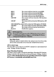
... system to try to boot from the 1st/2nd/3rd boot device. USB-CDROM The system will boot from the USB-interface ZIP drive. MSI Reminds You... USB-ZIP The system will boot from the USB-interface CD-ROM. Disabled Disable this item if your operating system doesn... The system will boot from the second HDD. HDD-2 The system will boot from any of the USB-interface devices, please set USB Keyboard/Mouse Support in SiS OnChip PCI Device of Integrated Peripherals to enable or disable the Intel Hyper Threading CPU function. LAN The system will boot from the...
... system to try to boot from the 1st/2nd/3rd boot device. USB-CDROM The system will boot from the USB-interface ZIP drive. MSI Reminds You... USB-ZIP The system will boot from the USB-interface CD-ROM. Disabled Disable this item if your operating system doesn... The system will boot from the second HDD. HDD-2 The system will boot from any of the USB-interface devices, please set USB Keyboard/Mouse Support in SiS OnChip PCI Device of Integrated Peripherals to enable or disable the Intel Hyper Threading CPU function. LAN The system will boot from the...
User Guide
Page 49
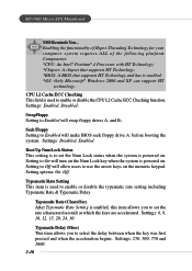
... has it enabled; *OS: Only Microsoft® Windows 2000 and XP can support HT technology. Boot Up NumLock Status This setting is to select the delay between when the key was first pressed and when the acceleration begins. MS-7005 Micro ATX Mainboard MSI Reminds You... Settings: 250, 500, 750 and 1000. 3-10 Swap Floppy Setting...
... has it enabled; *OS: Only Microsoft® Windows 2000 and XP can support HT technology. Boot Up NumLock Status This setting is to select the delay between when the key was first pressed and when the acceleration begins. MS-7005 Micro ATX Mainboard MSI Reminds You... Settings: 250, 500, 750 and 1000. 3-10 Swap Floppy Setting...
User Guide
Page 50
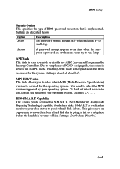
... your operating system. APIC Mode This field is able to a safe place before the hard disk becomes offline. You need to select the MPS version supported by your disk status to run Setup. Settings are described below: Option Setup Description The password prompt appears only when end users try to predict...
... your operating system. APIC Mode This field is able to a safe place before the hard disk becomes offline. You need to select the MPS version supported by your disk status to run Setup. Settings are described below: Option Setup Description The password prompt appears only when end users try to predict...
User Guide
Page 51
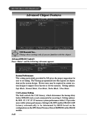
... suggestion for user to support loose layouts or slower memory. Setting options: Safe Mode, Normal Mode, Fast Mode, Turbo Mode, Ultra Mode. CAS Latency Setting The field controls the CAS latency, which determines the timing delay before SDRAM starts a read command after receiving it. MS-7005 Micro ATX Mainboard Advanced Chipset Features MSI Reminds You... The...
... suggestion for user to support loose layouts or slower memory. Setting options: Safe Mode, Normal Mode, Fast Mode, Turbo Mode, Ultra Mode. CAS Latency Setting The field controls the CAS latency, which determines the timing delay before SDRAM starts a read command after receiving it. MS-7005 Micro ATX Mainboard Advanced Chipset Features MSI Reminds You... The...
User Guide
Page 53
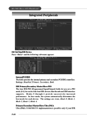
... the four IDE devices that the onboard IDE interface supports. The settings are: Auto, Mode 0, Mode 1, Mode 2, Mode 3, Mode 4. Settings: Disabled, Primary, Secondary, Both. In Auto mode, the system automatically determines the best mode for each device. Modes 0 through 4 provide successively increased performance. MS-7005 Micro ATX Mainboard Integrated Peripherals SiS OnChip IDE Device Press...
... the four IDE devices that the onboard IDE interface supports. The settings are: Auto, Mode 0, Mode 1, Mode 2, Mode 3, Mode 4. Settings: Disabled, Primary, Secondary, Both. In Auto mode, the system automatically determines the best mode for each device. Modes 0 through 4 provide successively increased performance. MS-7005 Micro ATX Mainboard Integrated Peripherals SiS OnChip IDE Device Press...


