
User Guide
Page 6
...Setup 3-2 Control Keys 3-2 Getting Help 3-3 The Main Menu 3-4 Standard CMOS Features 3-6 vi VGA Connector 2-12 RJ-45 LAN Jack 2-13 Audio Port Connectors 2-13 Midi/Joystick Connector 2-14 Parallel Port Connectors: LPT1 2-14 Connectors 2-15 Front Disk Drive Connector: FDD1 2-15 CD-In...15 Hard Disk Connectors: IDE1 & IDE2 2-16 Fan Power Connectors: CPUFAN1/SYSFAN1 2-17 Front Panel Connectors: JFP1 & JFP2 2-18 Front Panel Audio Connector: JAUD1 2-19 Front USB Connectors: JUSB1/JUSB2 2-20 SPDIF Connector: JSP1(Optional 2-21 Chassis intrusion Switch Connector: JCI1 2-22 Jumpers 2-...
...Setup 3-2 Control Keys 3-2 Getting Help 3-3 The Main Menu 3-4 Standard CMOS Features 3-6 vi VGA Connector 2-12 RJ-45 LAN Jack 2-13 Audio Port Connectors 2-13 Midi/Joystick Connector 2-14 Parallel Port Connectors: LPT1 2-14 Connectors 2-15 Front Disk Drive Connector: FDD1 2-15 CD-In...15 Hard Disk Connectors: IDE1 & IDE2 2-16 Fan Power Connectors: CPUFAN1/SYSFAN1 2-17 Front Panel Connectors: JFP1 & JFP2 2-18 Front Panel Audio Connector: JAUD1 2-19 Front USB Connectors: JUSB1/JUSB2 2-20 SPDIF Connector: JSP1(Optional 2-21 Chassis intrusion Switch Connector: JCI1 2-22 Jumpers 2-...
User Guide
Page 7
or 6-Channel Audio Function A-4 Testing the Connected Speakers A-8 Playing KaraOK A-10 Trouble shooting T-1 Glossary ...G-1 vii Advanced BIOS Features 3-8 Advanced Chipset Features 3-12 Integrated Peripherals 3-14 Power Management Setup 3-18 PNP/PCI Configurations 3-22 PC Health Status 3-24 Frequency/Voltage Control 3-25 Load Fail-Safe/Optimized Defaults 3-27 Set Supervisor/User Password 3-28 Appendix: Using 4- or 6-Channel Audio Function A-1 Installing the Audio Driver A-2 Using 4-
or 6-Channel Audio Function A-4 Testing the Connected Speakers A-8 Playing KaraOK A-10 Trouble shooting T-1 Glossary ...G-1 vii Advanced BIOS Features 3-8 Advanced Chipset Features 3-12 Integrated Peripherals 3-14 Power Management Setup 3-18 PNP/PCI Configurations 3-22 PC Health Status 3-24 Frequency/Voltage Control 3-25 Load Fail-Safe/Optimized Defaults 3-27 Set Supervisor/User Password 3-28 Appendix: Using 4- or 6-Channel Audio Function A-1 Installing the Audio Driver A-2 Using 4-
User Guide
Page 9
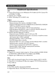
... without ECC. Integrated audio controller with fast write transaction - Slots h One AGP (Accelerated Graphics Port) slot that supports AGP 2.0 4X/2X. High performance 2D/3D and Video Accelerator h SiS962L MuTIOL Media I /O link ensures concurrency of up/down stream data transfer with 1.2GB/s bandwidth - Integrated PCI to 3.06GHz. MS-7005 Micro ATX Mainboard Mainboard Specifications CPU...
... without ECC. Integrated audio controller with fast write transaction - Slots h One AGP (Accelerated Graphics Port) slot that supports AGP 2.0 4X/2X. High performance 2D/3D and Video Accelerator h SiS962L MuTIOL Media I /O link ensures concurrency of up/down stream data transfer with 1.2GB/s bandwidth - Integrated PCI to 3.06GHz. MS-7005 Micro ATX Mainboard Mainboard Specifications CPU...
User Guide
Page 10
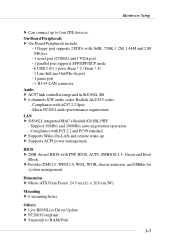
... devices. BIOS h 2MB Award BIOS with AC97 2.2 Spec - h Provides DMI 2.0, WFM 2.0, WOL, WOR, chassis intrusion, and SMBus for system management. Dimension h Micro-ATX Form Factor: 24.5 cm (L) x 20.0 cm (W). h 6 channels S/W audio codec Realtek ALC655 codec - On-Board Peripherals h On-Board Peripherals include: - 1 floppy port supports 2 FDDs with PCI 2.2 and PC99 standard. Support 10Mb...
... devices. BIOS h 2MB Award BIOS with AC97 2.2 Spec - h Provides DMI 2.0, WFM 2.0, WOL, WOR, chassis intrusion, and SMBus for system management. Dimension h Micro-ATX Form Factor: 24.5 cm (L) x 20.0 cm (W). h 6 channels S/W audio codec Realtek ALC655 codec - On-Board Peripherals h On-Board Peripherals include: - 1 floppy port supports 2 FDDs with PCI 2.2 and PC99 standard. Support 10Mb...

User Guide
Page 27
... mainboard provides one standard RJ-45 jack for microphones. 1/8" Stereo Audio Connectors Line Out Line In MIC MSI Reminds You... Using 4- Mic is provided to offer support for 6-channel audio operation and can connect a network cable to Local Area Network (LAN). For advanced audio application, Realtek ALC 655 is a connector for connection to the...
... mainboard provides one standard RJ-45 jack for microphones. 1/8" Stereo Audio Connectors Line Out Line In MIC MSI Reminds You... Using 4- Mic is provided to offer support for 6-channel audio operation and can connect a network cable to Local Area Network (LAN). For advanced audio application, Realtek ALC 655 is a connector for connection to the...
User Guide
Page 29
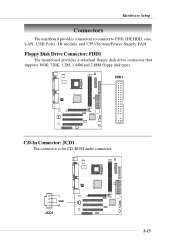
Floppy Disk Drive Connector: FDD1 The mainboard provides a standard floppy disk drive connector that supports 360K, 720K, 1.2M, 1.44M and 2.88M floppy disk types. FDD1 + CD-In Connector: JCD1 The connector is for CD-ROM audio connector. L GND R JCD1 + 2-15 Hardware Setup Connectors The mainboard provides connectors to connect to FDD, IDE HDD, case, LAN, USB Ports, IR module and CPU/System/Power Supply FAN.
Floppy Disk Drive Connector: FDD1 The mainboard provides a standard floppy disk drive connector that supports 360K, 720K, 1.2M, 1.44M and 2.88M floppy disk types. FDD1 + CD-In Connector: JCD1 The connector is for CD-ROM audio connector. L GND R JCD1 + 2-15 Hardware Setup Connectors The mainboard provides connectors to connect to FDD, IDE HDD, case, LAN, USB Ports, IR module and CPU/System/Power Supply FAN.

User Guide
Page 33
... DESCRIPTION 1 AUD_MIC Front panel microphone input signal 2 AUD_GND Ground used by analog audio circuits 3 AUD_MIC_BIAS Microphone power 4 AUD_VCC Filtered +5V used by analog audio circuits 5 AUD_FPOUT_R Right channel audio signal to front panel 6 AUD_RET_R Right channel audio signal return from front panel MSI Reminds You... Otherwise, the Line-Out connector on the back panel will...
... DESCRIPTION 1 AUD_MIC Front panel microphone input signal 2 AUD_GND Ground used by analog audio circuits 3 AUD_MIC_BIAS Microphone power 4 AUD_VCC Filtered +5V used by analog audio circuits 5 AUD_FPOUT_R Right channel audio signal to front panel 6 AUD_RET_R Right channel audio signal return from front panel MSI Reminds You... Otherwise, the Line-Out connector on the back panel will...

User Guide
Page 35
Connected to an external SPDIF Bracket for digital audio transmission. Hardware Setup SPDIF Connector: JSP1 (Optional) The connector is used to connect SPDIF (Sony & Philips Digital Interconnect Format) interface for digital audio transmission. JSP1 Pin Definition PIN SIGNAL 1 VCCS 2 SPDIF0 3 GND + 3 1 JSP1 The JSP1 supports SPDIF output only and can be connected to JSP1 SPDIF Bracket 2-21
Connected to an external SPDIF Bracket for digital audio transmission. Hardware Setup SPDIF Connector: JSP1 (Optional) The connector is used to connect SPDIF (Sony & Philips Digital Interconnect Format) interface for digital audio transmission. JSP1 Pin Definition PIN SIGNAL 1 VCCS 2 SPDIF0 3 GND + 3 1 JSP1 The JSP1 supports SPDIF output only and can be connected to JSP1 SPDIF Bracket 2-21
User Guide
Page 38
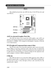
...settings for the expansion card, such as jumpers, switches or BIOS configuration. Meanwhile, read the documentation for ATX family motherboards. MS-7005 Micro ATX Mainboard Slots The motherboard provides one AGP slot, three 32-bit PCI bus slots and one CNR slot. PCI (Peripheral Component Interconnect...) Slots The PCI slots allow you unplug the power supply first. Its main processing is a specially designed audio,...
...settings for the expansion card, such as jumpers, switches or BIOS configuration. Meanwhile, read the documentation for ATX family motherboards. MS-7005 Micro ATX Mainboard Slots The motherboard provides one AGP slot, three 32-bit PCI bus slots and one CNR slot. PCI (Peripheral Component Interconnect...) Slots The PCI slots allow you unplug the power supply first. Its main processing is a specially designed audio,...

User Guide
Page 54
BIOS Setup hard drive supports it is detected, the onboard AC97 (Audio Codec'97) controller will be enabled; Disable the controller if you want to use other controller cards to use a USB keyboard/mouse in DOS, which ... system software both support Ultra DMA/33, Ultra DMA/66, Ultra DMA/100 and Ultra DMA/133, select Auto to detect whether an audio device is used . SiS AC97 Audio Auto allows the mainboard to enable BIOS support. If your hard drive and your system contains a Universal Serial Bus (USB) controller and...
BIOS Setup hard drive supports it is detected, the onboard AC97 (Audio Codec'97) controller will be enabled; Disable the controller if you want to use other controller cards to use a USB keyboard/mouse in DOS, which ... system software both support Ultra DMA/33, Ultra DMA/66, Ultra DMA/100 and Ultra DMA/133, select Auto to detect whether an audio device is used . SiS AC97 Audio Auto allows the mainboard to enable BIOS support. If your hard drive and your system contains a Universal Serial Bus (USB) controller and...
User Guide
Page 68
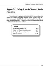
Using 4- ALC655 allows the board to install and use 4-/6-channel audio function on the board. or 6-Channel Audio Function The motherboard is equipped with Realtek ALC655 chip, which provides support for better surround sound effect. The section will tell you how to attach 4 or 6 speakers for 6-channel audio output, including 2 Front, 2 Rear, 1 Center and 1 Subwoofer channel. TOPICS Installing the Audio Driver A-2 Using 4-/6-Channel Audio Function A-4 Testing the Connected Speakers A-8 Playing KaraOK A-10 A-1 or 6-Channel Audio Function Appendix: Using 4-
Using 4- ALC655 allows the board to install and use 4-/6-channel audio function on the board. or 6-Channel Audio Function The motherboard is equipped with Realtek ALC655 chip, which provides support for better surround sound effect. The section will tell you how to attach 4 or 6 speakers for 6-channel audio output, including 2 Front, 2 Rear, 1 Center and 1 Subwoofer channel. TOPICS Installing the Audio Driver A-2 Using 4-/6-Channel Audio Function A-4 Testing the Connected Speakers A-8 Playing KaraOK A-10 A-1 or 6-Channel Audio Function Appendix: Using 4-
User Guide
Page 69
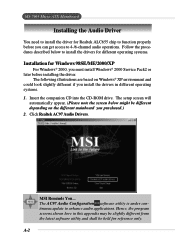
The following illustrations are based on the different mainboard you purchased.) 2. Click Realtek AC97 Audio Drivers. MSI Reminds You... Hence, the program screens shown here in this appendix may be slightly different from the latest software utility and ...; 2000, you must install Windows® 2000 Service Pack2 or later before you install the drivers in different operating systems. 1. MS-7005 Micro ATX Mainboard Installing the Audio Driver You need to install the driver for Realtek ALC655 chip to function properly before installing the driver. Follow the procedures described below...
The following illustrations are based on the different mainboard you purchased.) 2. Click Realtek AC97 Audio Drivers. MSI Reminds You... Hence, the program screens shown here in this appendix may be slightly different from the latest software utility and ...; 2000, you must install Windows® 2000 Service Pack2 or later before you install the drivers in different operating systems. 1. MS-7005 Micro ATX Mainboard Installing the Audio Driver You need to install the driver for Realtek ALC655 chip to function properly before installing the driver. Follow the procedures described below...

User Guide
Page 70
or 6-Channel Audio Function 3. Click Next to restart the system. Using 4- Click Finish to start installing files into the system. 4. Select this option A-3
or 6-Channel Audio Function 3. Click Next to restart the system. Using 4- Click Finish to start installing files into the system. 4. Select this option A-3
User Guide
Page 71
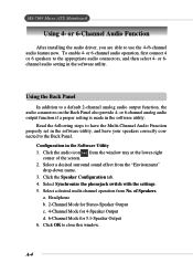
... Stereo-Speaker Output c. 4-Channel Mode for 4-Speaker Output d. 6-Channel Mode for 5.1-Speaker Output 6. Click OK to the appropriate audio connectors, and then select 4- To enable 4- Select a desired surround sound effect from No. A-4 Configuration in the software utility, and ...correctly connected to use the 4-/6-channel audio feature now. Select a desired multi-channel operation from the "Environment" drop-down menu. 3. or 6-Channel Audio Function After installing the audio driver, you are able to the Back Panel. MS-7005 Micro ATX Mainboard Using 4- Using the Back ...
... Stereo-Speaker Output c. 4-Channel Mode for 4-Speaker Output d. 6-Channel Mode for 5.1-Speaker Output 6. Click OK to the appropriate audio connectors, and then select 4- To enable 4- Select a desired surround sound effect from No. A-4 Configuration in the software utility, and ...correctly connected to use the 4-/6-channel audio feature now. Select a desired multi-channel operation from the "Environment" drop-down menu. 3. or 6-Channel Audio Function After installing the audio driver, you are able to the Back Panel. MS-7005 Micro ATX Mainboard Using 4- Using the Back ...

User Guide
Page 72
or 6-Channel Audio Function A-5 Using 4-
or 6-Channel Audio Function A-5 Using 4-

User Guide
Page 73
... 4-Channel Mode for 4-Speaker Output The audio jacks on the back panel when 4-Channel Mode is selected. 1 MIC 2 * Line Out (Rear channels) 3 Line Out (Front channels) Back Panel * Line In function is selected. MS-7005 Micro ATX Mainboard Connecting the Speakers When you have ...set the Multi-Channel Audio Function mode properly in the software utility, connect your speakers to the correct phone jacks in accordance with ...
... 4-Channel Mode for 4-Speaker Output The audio jacks on the back panel when 4-Channel Mode is selected. 1 MIC 2 * Line Out (Rear channels) 3 Line Out (Front channels) Back Panel * Line In function is selected. MS-7005 Micro ATX Mainboard Connecting the Speakers When you have ...set the Multi-Channel Audio Function mode properly in the software utility, connect your speakers to the correct phone jacks in accordance with ...

User Guide
Page 74
You can purchase the converter from a speaker store. or 6-Channel Audio Function „ 6-Channel Mode for 6-Speaker Output Refer to the following diagram and caption for 6-Speaker Output is selected. 1 Line Out (Center and Back Panel ... Out (Rear channels) 3 * Line Out (Front channels) * Both Line In and MIC function are converted to exchange center and subwoofer audio signals. A-7 If the Center and Subwoofer speaker exchange their audio channels when you play video or music on the computer, a converter may be required to Line Out function when 4-Channel Mode...
You can purchase the converter from a speaker store. or 6-Channel Audio Function „ 6-Channel Mode for 6-Speaker Output Refer to the following diagram and caption for 6-Speaker Output is selected. 1 Line Out (Center and Back Panel ... Out (Rear channels) 3 * Line Out (Front channels) * Both Line In and MIC function are converted to exchange center and subwoofer audio signals. A-7 If the Center and Subwoofer speaker exchange their audio channels when you play video or music on the computer, a converter may be required to Line Out function when 4-Channel Mode...

User Guide
Page 75
...speaker to make sound, then check whether the cable is inserted firmly to test by clicking it. A-8 MS-7005 Micro ATX Mainboard Testing the Connected Speakers To ensure that 4- Click the audio icon from the window tray at the lower-right corner of Speakers" column. Click the Speaker Test tab.... 3. Center Front Right Front Left Rear Right Rear Left Subwoofer MSI Reminds You... 6 speakers appear on the window. If any speaker fails to make sure every speaker work properly. or 6-channel audio operation works properly, you select "6-Channel Mode" in the "No. The ...
...speaker to make sound, then check whether the cable is inserted firmly to test by clicking it. A-8 MS-7005 Micro ATX Mainboard Testing the Connected Speakers To ensure that 4- Click the audio icon from the window tray at the lower-right corner of Speakers" column. Click the Speaker Test tab.... 3. Center Front Right Front Left Rear Right Rear Left Subwoofer MSI Reminds You... 6 speakers appear on the window. If any speaker fails to make sure every speaker work properly. or 6-channel audio operation works properly, you select "6-Channel Mode" in the "No. The ...

User Guide
Page 76
ing from the center speaker and subwoofer is swapped, you are testing the speakers in 6-Channel Mode, if the sound com- Using 4- While you should select Swap Center/Subwoofer Output to readjust these two channels. Select this function A-9 or 6-Channel Audio Function 4.
ing from the center speaker and subwoofer is swapped, you are testing the speakers in 6-Channel Mode, if the sound com- Using 4- While you should select Swap Center/Subwoofer Output to readjust these two channels. Select this function A-9 or 6-Channel Audio Function 4.

User Guide
Page 77
Playing KaraOK 1. Click the audio icon from the window tray at the lower-right corner of the screen. 2. A-10 Note that this function applies only for you to close this window. In the Sound Effect tab, select Voice Cancellation under "KaraOK." 3. Click OK to sing the song. MS-7005 Micro ATX Mainboard Playing KaraOK The KaraOK function will automatically remove human voice (lyrics) and leave melody for 2-channel audio operation.
Playing KaraOK 1. Click the audio icon from the window tray at the lower-right corner of the screen. 2. A-10 Note that this function applies only for you to close this window. In the Sound Effect tab, select Voice Cancellation under "KaraOK." 3. Click OK to sing the song. MS-7005 Micro ATX Mainboard Playing KaraOK The KaraOK function will automatically remove human voice (lyrics) and leave melody for 2-channel audio operation.
