User Guide
Page 5
... Fan 2-5 Memory 2-7 DDR Module Combination 2-8 Installing DDR Modules 2-8 Power Supply 2-9 ATX 20-Pin Power Connector: CONN1 2-9 ATX 12V Power Connector: ATX12V 2-9 Back Panel 2-10 Mouse Connector 2-10 Keyboard Connector 2-11 USB Connector 2-11 Serial Port Connectors: COMA 2-12 v Getting Started 1-1 Mainboard Specifications 1-2 Mainboard Layout 1-4 MSI Special Features 1-5 PC Alert™ 4 1-5 Live BIOS™/Live Driver...
... Fan 2-5 Memory 2-7 DDR Module Combination 2-8 Installing DDR Modules 2-8 Power Supply 2-9 ATX 20-Pin Power Connector: CONN1 2-9 ATX 12V Power Connector: ATX12V 2-9 Back Panel 2-10 Mouse Connector 2-10 Keyboard Connector 2-11 USB Connector 2-11 Serial Port Connectors: COMA 2-12 v Getting Started 1-1 Mainboard Specifications 1-2 Mainboard Layout 1-4 MSI Special Features 1-5 PC Alert™ 4 1-5 Live BIOS™/Live Driver...

User Guide
Page 8
Hardware Setup Getting Started Thank you for high-speed data transmission. The 651M-L/650GM-L series is based on SiS® 651/650GX (702 pin BGA) & SiS® 962L MuTIOL Media I/O (371 BGA) chipsets and provides 6 USB 2.0 ports for purchasing 651M-L/650GM-L Series (MS-7005) v1.X Micro ATX mainboard. With all these special designs, the 651M-L/650GM-L series delivers a high performance and professional desktop platform solution. 1-1
Hardware Setup Getting Started Thank you for high-speed data transmission. The 651M-L/650GM-L series is based on SiS® 651/650GX (702 pin BGA) & SiS® 962L MuTIOL Media I/O (371 BGA) chipsets and provides 6 USB 2.0 ports for purchasing 651M-L/650GM-L Series (MS-7005) v1.X Micro ATX mainboard. With all these special designs, the 651M-L/650GM-L series delivers a high performance and professional desktop platform solution. 1-1
User Guide
Page 9
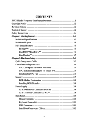
... interface with AC97 interface - Integrated MuTIOL connect to SiS962L MuTIOL Media I/O - h Hyper-Threading CPU for SiS 651) memory controller - Integrated PCI to SiS series NB - MS-7005 Micro ATX Mainboard Mainboard Specifications CPU h Socket 478 for P4 processors (Willamette 478 / Northwood 478 / Celeron 478) at 400 MHz/ 533 MHz h Supports up to 2GB memory size without...
... interface with AC97 interface - Integrated MuTIOL connect to SiS962L MuTIOL Media I/O - h Hyper-Threading CPU for SiS 651) memory controller - Integrated PCI to SiS series NB - MS-7005 Micro ATX Mainboard Mainboard Specifications CPU h Socket 478 for P4 processors (Willamette 478 / Northwood 478 / Celeron 478) at 400 MHz/ 533 MHz h Supports up to 2GB memory size without...

User Guide
Page 11
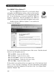
AT X Power Supply FDD1 DDR 1 DDR 2 S Y S FA N 1 IDE 2 IDE 1 MS-7005 Micro ATX Mainboard Mainboard Layout Top : mouse Bottom: keyboard BIOS Winbond W83697HF Top : Parallel Port Bottom: COM A VGA Port CPUFAN1 Top : Game port Bottom: Line-Out Line-In Mic AT X 1 2 V SiS 651/650GX T: LAN jack B: USB ports Realtek 8201BL JSP1 JCD1 AGP Slot PCI Slot 1 PCI Slot 2 JUSB2 Codec CNR PCI Slot 3 JAUD1 JUSB1 BATT + SiS 962L J BAT 1 JCI1 JFP1 JFP2 651M-L/650GM-L Series (MS-7005) v1.X Micro ATX Mainboard 1-4
AT X Power Supply FDD1 DDR 1 DDR 2 S Y S FA N 1 IDE 2 IDE 1 MS-7005 Micro ATX Mainboard Mainboard Layout Top : mouse Bottom: keyboard BIOS Winbond W83697HF Top : Parallel Port Bottom: COM A VGA Port CPUFAN1 Top : Game port Bottom: Line-Out Line-In Mic AT X 1 2 V SiS 651/650GX T: LAN jack B: USB ports Realtek 8201BL JSP1 JCD1 AGP Slot PCI Slot 1 PCI Slot 2 JUSB2 Codec CNR PCI Slot 3 JAUD1 JUSB1 BATT + SiS 962L J BAT 1 JCI1 JFP1 JFP2 651M-L/650GM-L Series (MS-7005) v1.X Micro ATX Mainboard 1-4
User Guide
Page 13
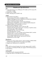
...VGA driver online. Updates the utilities online. z Live BIOS - z Live Driver - MS-7005 Micro ATX Mainboard Live BIOS™/Live Driver™ The Live BIOS™/Live Driver™ is displayed. After the installation, the "MSI Live Update 2" icon (as shown on the right) will appear: Five buttons are ...the screen. For more information on the update instructions, insert the companion CD and refer to start the update process. Double click the "MSI Live Update 2" icon, and the following screen will appear on the leftmost pane of the functions listed above, a "sorry" message ...
...VGA driver online. Updates the utilities online. z Live BIOS - z Live Driver - MS-7005 Micro ATX Mainboard Live BIOS™/Live Driver™ The Live BIOS™/Live Driver™ is displayed. After the installation, the "MSI Live Update 2" icon (as shown on the right) will appear: Five buttons are ...the screen. For more information on the update instructions, insert the companion CD and refer to start the update process. Double click the "MSI Live Update 2" icon, and the following screen will appear on the leftmost pane of the functions listed above, a "sorry" message ...

User Guide
Page 15
Hardware Setup Hardware Setup This chapter tells you how to install the CPU, memory modules, and expansion cards, as well as the mouse, keyboard, etc. It also provides the instructions on connecting the peripheral devices, such as how to setup the jumpers on the mainboard. Hardware Setup Chapter 2. While doing the installation, be careful in holding the components and follow the installation procedures. 2-1
Hardware Setup Hardware Setup This chapter tells you how to install the CPU, memory modules, and expansion cards, as well as the mouse, keyboard, etc. It also provides the instructions on connecting the peripheral devices, such as how to setup the jumpers on the mainboard. Hardware Setup Chapter 2. While doing the installation, be careful in holding the components and follow the installation procedures. 2-1

User Guide
Page 17
... attached on the computer. Replacing the CPU While replacing the CPU, always turn off the ATX power supply or unplug the power supply's power cord from overheating. Hardware Setup Central Processing Unit: CPU The mainboard supports Intel® Pentium® 4 Willamette, Celeron, Northwood processor in the 478 pin package...100MHz x 17 = 1.7GHz Memory Speed/CPU FSB Support Matrix Memory FSB DDR 266 400 MHz OK 533 MHz OK DDR 333 OK OK MSI Reminds You... When you do not find the heat sink and cooling fan, contact your dealer to protect the CPU from grounded outlet first to...
... attached on the computer. Replacing the CPU While replacing the CPU, always turn off the ATX power supply or unplug the power supply's power cord from overheating. Hardware Setup Central Processing Unit: CPU The mainboard supports Intel® Pentium® 4 Willamette, Celeron, Northwood processor in the 478 pin package...100MHz x 17 = 1.7GHz Memory Speed/CPU FSB Support Matrix Memory FSB DDR 266 400 MHz OK 533 MHz OK DDR 333 OK OK MSI Reminds You... When you do not find the heat sink and cooling fan, contact your dealer to protect the CPU from grounded outlet first to...
User Guide
Page 18
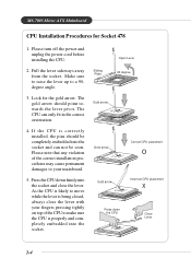
MS-7005 Micro ATX Mainboard CPU Installation Procedures for the gold arrow. Pull the lever sideways away from the socket. Look for Socket 478 1. As the CPU is likely to your mainboard. 5. Press the CPU down the CPU Close Lever 2-4 Sliding Plate Open Lever 90 degree Gold arrow Gold arrow Correct CPU placement O Gold arrow Incorrect CPU...
MS-7005 Micro ATX Mainboard CPU Installation Procedures for the gold arrow. Pull the lever sideways away from the socket. Look for Socket 478 1. As the CPU is likely to your mainboard. 5. Press the CPU down the CPU Close Lever 2-4 Sliding Plate Open Lever 90 degree Gold arrow Gold arrow Correct CPU placement O Gold arrow Incorrect CPU...
User Guide
Page 20
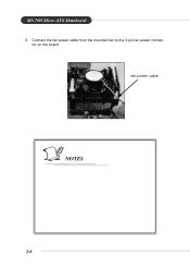
fan power cable NOTES 2-6 tor on the board. MS-7005 Micro ATX Mainboard 5. Connect the fan power cable from the mounted fan to the 3-pin fan power connec-
fan power cable NOTES 2-6 tor on the board. MS-7005 Micro ATX Mainboard 5. Connect the fan power cable from the mounted fan to the 3-pin fan power connec-

User Guide
Page 21
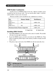
To operate properly, at least one DIMM module must be installed. + DDR DIMM Slots (DDR 1~2) Introduction to DDR SDRAM DDR (Double Data Rate) SDRAM is similar to 3.3 volts used in SDR SDRAM, and requires 184-pin DIMM modules rather than 168-pin DIMM modules used by transferring data twice per cycle. It uses 2.5 volts as opposed to conventional SDRAM, but doubles the rate by SDR SDRAM. 2-7 Hardware Setup Memory The mainboard provides two 184-pin unbuffered DDR200/DDR266/ DDR333 DDR SDRAM, and supports the memory size up to 2GB.
To operate properly, at least one DIMM module must be installed. + DDR DIMM Slots (DDR 1~2) Introduction to DDR SDRAM DDR (Double Data Rate) SDRAM is similar to 3.3 volts used in SDR SDRAM, and requires 184-pin DIMM modules rather than 168-pin DIMM modules used by transferring data twice per cycle. It uses 2.5 volts as opposed to conventional SDRAM, but doubles the rate by SDR SDRAM. 2-7 Hardware Setup Memory The mainboard provides two 184-pin unbuffered DDR200/DDR266/ DDR333 DDR SDRAM, and supports the memory size up to 2GB.
User Guide
Page 22
... of the DIMM slot will only fit in the right orientation. 2. Volt Notch MSI Reminds You... Insert the DIMM memory module vertically into the DIMM slot. You can install either single- Then push it in until the golden finger on the slots. MS-7005 Micro ATX Mainboard DDR Module Combination Install at each side of module.
... of the DIMM slot will only fit in the right orientation. 2. Volt Notch MSI Reminds You... Insert the DIMM memory module vertically into the DIMM slot. You can install either single- Then push it in until the golden finger on the slots. MS-7005 Micro ATX Mainboard DDR Module Combination Install at each side of module.
User Guide
Page 23
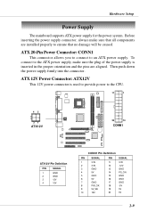
...supply, make sure that no damage will be caused. Then push down the power supply firmly into the connector. Hardware Setup Power Supply The mainboard supports ATX power supply for the power system. Before inserting the power supply connector, always make sure the plug of the power supply is used to ...provide power to an ATX power supply. ATX 20-Pin Power Connector: CONN1 This connector allows you to connect to the CPU. 11 1 42 31 ATX12V 20 10 CONN1 + ATX12V Pin...
...supply, make sure that no damage will be caused. Then push down the power supply firmly into the connector. Hardware Setup Power Supply The mainboard supports ATX power supply for the power system. Before inserting the power supply connector, always make sure the plug of the power supply is used to ...provide power to an ATX power supply. ATX 20-Pin Power Connector: CONN1 This connector allows you to connect to the CPU. 11 1 42 31 ATX12V 20 10 CONN1 + ATX12V Pin...
User Guide
Page 24
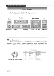
MS-7005 Micro ATX Mainboard Back Panel The back panel provides the following connectors: Mouse Parallel Midi/Joystick LAN Keyboard COMA VGA Port L-out L-in MIC USB Ports Mouse Connector The mainboard provides a standard PS/2® mouse mini DIN connector for attaching a PS/2® mouse. The connector location and pin assignments are as follows: 6 5 4 3 2 1 PS/2 Mouse (6-pin...
MS-7005 Micro ATX Mainboard Back Panel The back panel provides the following connectors: Mouse Parallel Midi/Joystick LAN Keyboard COMA VGA Port L-out L-in MIC USB Ports Mouse Connector The mainboard provides a standard PS/2® mouse mini DIN connector for attaching a PS/2® mouse. The connector location and pin assignments are as follows: 6 5 4 3 2 1 PS/2 Mouse (6-pin...

User Guide
Page 25
...(6-pin Female) 5 6 Keyboard DATA NC GND VCC Keyboard Clock NC Keyboard DATA No connection Ground +5V Keyboard clock No connection USB Connectors The mainboard provides a UHCI (Universal Host Controller Interface) Universal Serial Bus root for attaching a PS/2® keyboard. You can plug a PS/2® keyboard ... Channel 0 Ground +5V Negative Data Channel 1 Positive Data Channel 1 Ground 2-11 Hardware Setup Keyboard Connector The mainboard provides a standard PS/2® keyboard mini DIN connector for attaching USB devices such as keyboard, mouse or other USB-compatible devices.
...(6-pin Female) 5 6 Keyboard DATA NC GND VCC Keyboard Clock NC Keyboard DATA No connection Ground +5V Keyboard clock No connection USB Connectors The mainboard provides a UHCI (Universal Host Controller Interface) Universal Serial Bus root for attaching a PS/2® keyboard. You can plug a PS/2® keyboard ... Channel 0 Ground +5V Negative Data Channel 1 Positive Data Channel 1 Ground 2-11 Hardware Setup Keyboard Connector The mainboard provides a standard PS/2® keyboard mini DIN connector for attaching USB devices such as keyboard, mouse or other USB-compatible devices.
User Guide
Page 26
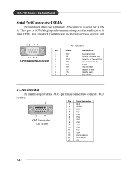
... 1 RED 2 GREEN 3 BLUE 4 N/C 5 GND 6 GND 7 GND 8 GND 9 +5V 10 GND 11 N/C 12 SDA 13 Horizontal Sync 14 Vertical Sync 15 SCL 2-12 MS-7005 Micro ATX Mainboard Serial Port Connectors: COMA The mainboard offers one 9-pin male DIN connector as serial port COM A. This port is 16550A high speed communication ports that send/receive 16 bytes...
... 1 RED 2 GREEN 3 BLUE 4 N/C 5 GND 6 GND 7 GND 8 GND 9 +5V 10 GND 11 N/C 12 SDA 13 Horizontal Sync 14 Vertical Sync 15 SCL 2-12 MS-7005 Micro ATX Mainboard Serial Port Connectors: COMA The mainboard offers one 9-pin male DIN connector as serial port COM A. This port is 16550A high speed communication ports that send/receive 16 bytes...

User Guide
Page 27
... connector for Speakers or Headphones. or 6-Channel Audio Function. 2-13 Line In is a connector for microphones. 1/8" Stereo Audio Connectors Line Out Line In MIC MSI Reminds You... Pin Definition RJ-45 LAN Jack PIN SIGNAL 1 TDP 2 TDN 3 RDP 4 NC 5 NC 6 RDN 7 NC 8 NC DESCRIPTION Transmit...offer support for 6-channel audio operation and can connect a network cable to 4-/6-channel audio. Hardware Setup RJ-45 LAN Jack The mainboard provides one standard RJ-45 jack for connection to Appendix. For more information on 6-channel audio operation, please refer to Local Area Network...
... connector for Speakers or Headphones. or 6-Channel Audio Function. 2-13 Line In is a connector for microphones. 1/8" Stereo Audio Connectors Line Out Line In MIC MSI Reminds You... Pin Definition RJ-45 LAN Jack PIN SIGNAL 1 TDP 2 TDN 3 RDP 4 NC 5 NC 6 RDN 7 NC 8 NC DESCRIPTION Transmit...offer support for 6-channel audio operation and can connect a network cable to 4-/6-channel audio. Hardware Setup RJ-45 LAN Jack The mainboard provides one standard RJ-45 jack for connection to Appendix. For more information on 6-channel audio operation, please refer to Local Area Network...
User Guide
Page 28
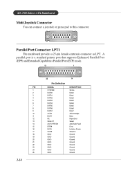
... Ground 20 GND Ground 21 GND Ground 22 GND Ground 23 GND Ground 24 GND Ground 25 GND Ground 2-14 Parallel Port Connector: LPT1 The mainboard provides a 25-pin female centronic connector as LPT. MS-7005 Micro ATX Mainboard Midi/Joystick Connector You can connect a joystick or game pad to this connector.
... Ground 20 GND Ground 21 GND Ground 22 GND Ground 23 GND Ground 24 GND Ground 25 GND Ground 2-14 Parallel Port Connector: LPT1 The mainboard provides a 25-pin female centronic connector as LPT. MS-7005 Micro ATX Mainboard Midi/Joystick Connector You can connect a joystick or game pad to this connector.
User Guide
Page 29
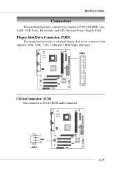
Floppy Disk Drive Connector: FDD1 The mainboard provides a standard floppy disk drive connector that supports 360K, 720K, 1.2M, 1.44M and 2.88M floppy disk types. L GND R JCD1 + 2-15 FDD1 + CD-In Connector: JCD1 The connector is for CD-ROM audio connector. Hardware Setup Connectors The mainboard provides connectors to connect to FDD, IDE HDD, case, LAN, USB Ports, IR module and CPU/System/Power Supply FAN.
Floppy Disk Drive Connector: FDD1 The mainboard provides a standard floppy disk drive connector that supports 360K, 720K, 1.2M, 1.44M and 2.88M floppy disk types. L GND R JCD1 + 2-15 FDD1 + CD-In Connector: JCD1 The connector is for CD-ROM audio connector. Hardware Setup Connectors The mainboard provides connectors to connect to FDD, IDE HDD, case, LAN, USB Ports, IR module and CPU/System/Power Supply FAN.
User Guide
Page 30
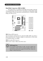
... to Slave mode by setting the jumper accordingly. Refer to IDE1. IDE2 (Secondary IDE Connector) IDE2 can connect a Master and a Slave drive. MSI Reminds You... You can connect up to four hard disk drives, CD-ROM, 120MB Floppy and other devices. + IDE2 IDE1 IDE1 (Primary IDE ... on cable, you must configure second hard drive to Slave mode by hard disk vendors for jumper setting instructions. 2-16 MS-7005 Micro ATX Mainboard Hard Disk Connectors: IDE1 & IDE2 The mainboard has a 32-bit Enhanced PCI IDE and Ultra DMA 33/66/100/ 133 controller that provides PIO mode 0~4, Bus Master...
... to Slave mode by setting the jumper accordingly. Refer to IDE1. IDE2 (Secondary IDE Connector) IDE2 can connect a Master and a Slave drive. MSI Reminds You... You can connect up to four hard disk drives, CD-ROM, 120MB Floppy and other devices. + IDE2 IDE1 IDE1 (Primary IDE ... on cable, you must configure second hard drive to Slave mode by hard disk vendors for jumper setting instructions. 2-16 MS-7005 Micro ATX Mainboard Hard Disk Connectors: IDE1 & IDE2 The mainboard has a 32-bit Enhanced PCI IDE and Ultra DMA 33/66/100/ 133 controller that provides PIO mode 0~4, Bus Master...

User Guide
Page 31
... the actual CPU temperature. 2-17 When connecting the wire to the connectors, always take advantage of the CPU fan control. If the mainboard has a System Hardware Monitor chipset on-board, you must use a specially designed fan with +12V. GND +12V SENSOR CPUFAN1 GND +12V SENSOR... SYSFAN1 + MSI Reminds You... 1. CPUFAN1 supports the fan control. Hardware Setup Fan Power Connectors: CPUFAN1/SYSFAN1 The CPUFAN1 (processor fan) and SYSFAN1 (system fan) ...
... the actual CPU temperature. 2-17 When connecting the wire to the connectors, always take advantage of the CPU fan control. If the mainboard has a System Hardware Monitor chipset on-board, you must use a specially designed fan with +12V. GND +12V SENSOR CPUFAN1 GND +12V SENSOR... SYSFAN1 + MSI Reminds You... 1. CPUFAN1 supports the fan control. Hardware Setup Fan Power Connectors: CPUFAN1/SYSFAN1 The CPUFAN1 (processor fan) and SYSFAN1 (system fan) ...


