User Guide
Page 4
... setting it work well or you can not step on the enclosure are for further guidance. Technical Support If a problem arises with the same or equivalent type recommended by a service personnel: l The power cord or plug is incorrectly replaced. Keep this User's Manual for FAQ, technical guide, BIOS updates, driver updates, and other information: http://www.msi.com.tw/ Contact our technical staff at: support@msi.com.tw Safety Instructions...
... setting it work well or you can not step on the enclosure are for further guidance. Technical Support If a problem arises with the same or equivalent type recommended by a service personnel: l The power cord or plug is incorrectly replaced. Keep this User's Manual for FAQ, technical guide, BIOS updates, driver updates, and other information: http://www.msi.com.tw/ Contact our technical staff at: support@msi.com.tw Safety Instructions...

User Guide
Page 5
... Technical Support iv Safety Instructions iv Chapter 1.Getting Started 1-1 Mainboard Specifications 1-2 Mainboard Layout 1-4 MSI Special Features 1-5 FuzzyLogic™ 4 1-5 LiveBIOS™/LiveDriver 1-6 Live Monitor 1-7 D-Bracket™ 2 (Optional 1-8 PCAlert™ 4 1-10 MSI DVD5.1 Channel (Optional 1-12 CPU Thermal Protection 1-14 S-Bracket (Optional 1-14 Chapter 2. Hardware Setup 2-1 Quick Components Guide 2-2 Central Processing Unit: CPU 2-3 CPU Core Speed Derivation Procedure 2-3 Thermal Issue for CPU 2-3 CPU Installation Procedures for Socket 462 2-4 Installing...
... Technical Support iv Safety Instructions iv Chapter 1.Getting Started 1-1 Mainboard Specifications 1-2 Mainboard Layout 1-4 MSI Special Features 1-5 FuzzyLogic™ 4 1-5 LiveBIOS™/LiveDriver 1-6 Live Monitor 1-7 D-Bracket™ 2 (Optional 1-8 PCAlert™ 4 1-10 MSI DVD5.1 Channel (Optional 1-12 CPU Thermal Protection 1-14 S-Bracket (Optional 1-14 Chapter 2. Hardware Setup 2-1 Quick Components Guide 2-2 Central Processing Unit: CPU 2-3 CPU Core Speed Derivation Procedure 2-3 Thermal Issue for CPU 2-3 CPU Installation Procedures for Socket 462 2-4 Installing...
User Guide
Page 7
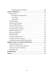
...Channel Audio Function A-1 Installing the Audio Driver A-2 Using 4- BIOS Setup 3-1 Entering Setup 3-2 Selecting the First Boot Device 3-2 Control Keys 3-3 Getting Help 3-3 The Main Menu 3-4 Standard CMOS Features 3-6 Advanced BIOS Features 3-8 Advanced Chipset Features 3-13 Power Management Features 3-17 PNP/PCI Configurations 3-21 Integrated Peripherals 3-23 PC Health Status 3-26 Frequency/Voltage Control 3-27 Set Supervisor/User Password 3-29 Load High Performance/BIOS Setup Defaults 3-30 Appendix: Using 4- or 6-Channel Audio Function A-4 Testing the Connected Speakers...
...Channel Audio Function A-1 Installing the Audio Driver A-2 Using 4- BIOS Setup 3-1 Entering Setup 3-2 Selecting the First Boot Device 3-2 Control Keys 3-3 Getting Help 3-3 The Main Menu 3-4 Standard CMOS Features 3-6 Advanced BIOS Features 3-8 Advanced Chipset Features 3-13 Power Management Features 3-17 PNP/PCI Configurations 3-21 Integrated Peripherals 3-23 PC Health Status 3-26 Frequency/Voltage Control 3-27 Set Supervisor/User Password 3-29 Load High Performance/BIOS Setup Defaults 3-30 Appendix: Using 4- or 6-Channel Audio Function A-4 Testing the Connected Speakers...
User Guide
Page 9
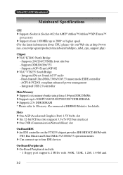
... bus - Dual channel Ultra DMA 33/66/100/133 master mode EIDE controller - ACPI & PC2001 compliant enhanced power management - Slots † One AGP (Accelerated Graphics Port) 1.5V 8x/4x slot † Six 32-bit PCI bus slots (support 3.3v/5v PCI bus interface) † One CNR (Communication Network Riser) slot On-Board IDE † An IDE controller on the VT8235 chipset provides IDE HDD/CD-ROM with PIO, Bus Master and Ultra DMA133/100/66/33 operation modes † Can connect...
... bus - Dual channel Ultra DMA 33/66/100/133 master mode EIDE controller - ACPI & PC2001 compliant enhanced power management - Slots † One AGP (Accelerated Graphics Port) 1.5V 8x/4x slot † Six 32-bit PCI bus slots (support 3.3v/5v PCI bus interface) † One CNR (Communication Network Riser) slot On-Board IDE † An IDE controller on the VT8235 chipset provides IDE HDD/CD-ROM with PIO, Bus Master and Ultra DMA133/100/66/33 operation modes † Can connect...
User Guide
Page 26
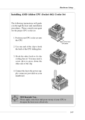
... fan set onto the CPU. 2. Connect the fan to the power supply connector provided on top of the clip to press down the other latch to dissipate the heat more effectively. 2-5 Apply some heat sink paste on your agent for the proper CPU cooler set. 1. Use one end of your CPU cooler set . Please consult your mainboard. Hardware Setup Installing AMD Athlon CPU (Socket 462) Cooler Set The following instructions will guide...
... fan set onto the CPU. 2. Connect the fan to the power supply connector provided on top of the clip to press down the other latch to dissipate the heat more effectively. 2-5 Apply some heat sink paste on your agent for the proper CPU cooler set. 1. Use one end of your CPU cooler set . Please consult your mainboard. Hardware Setup Installing AMD Athlon CPU (Socket 462) Cooler Set The following instructions will guide...
User Guide
Page 27
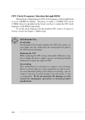
... the CPU clock frequency in Chapter 3. MS-6712 ATX Mainboard CPU Clock Frequency Selection through BIOS The hardware configuration for the installed CPU, refer to support overclocking. We do not guarantee the damages or risks caused by default. BIOS Setup. Therefore, to make sure your components are able to 100MHz by inadequate operation or beyond product specifications is set the clock frequency for CPU clock frequency of CPU. Replacing the CPU While replacing the CPU, always turn off the ATX power supply or...
... the CPU clock frequency in Chapter 3. MS-6712 ATX Mainboard CPU Clock Frequency Selection through BIOS The hardware configuration for the installed CPU, refer to support overclocking. We do not guarantee the damages or risks caused by default. BIOS Setup. Therefore, to make sure your components are able to 100MHz by inadequate operation or beyond product specifications is set the clock frequency for CPU clock frequency of CPU. Replacing the CPU While replacing the CPU, always turn off the ATX power supply or...
User Guide
Page 48
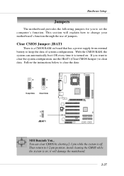
... how to change your motherboard's function through the use the JBAT1 (Clear CMOS Jumper ) to clear data. With the CMOS RAM, the system can clear CMOS by shorting 2-3 pin while the system is a CMOS RAM on ; Then return to clear the data: 3 3 1 Keep Data 1 Clear Data 3 1 JBAT1 MSI Reminds You... Clear CMOS Jumper: JBAT1 There is off. Follow the instructions below to 1-2 pin position. it is on board that has a power supply from external battery to set the...
... how to change your motherboard's function through the use the JBAT1 (Clear CMOS Jumper ) to clear data. With the CMOS RAM, the system can clear CMOS by shorting 2-3 pin while the system is a CMOS RAM on ; Then return to clear the data: 3 3 1 Keep Data 1 Clear Data 3 1 JBAT1 MSI Reminds You... Clear CMOS Jumper: JBAT1 There is off. Follow the instructions below to 1-2 pin position. it is on board that has a power supply from external battery to set the...

User Guide
Page 49
...) Slots The PCI slots allow you to insert the AGP graphics card. CNR is a specially designed network, audio, or modem riser card for the expansion card, such as jumpers, switches or BIOS configuration. AGP Slot PCI Slots CNR Slot AGP (Accelerated Graphics Port) Slot The AGP slot allows you to insert the expansion cards to make sure that you to directly access main memory. CNR (Communication Network Riser) Slot The CNR slot allows you unplug the power supply first. The mainboard supports...
...) Slots The PCI slots allow you to insert the AGP graphics card. CNR is a specially designed network, audio, or modem riser card for the expansion card, such as jumpers, switches or BIOS configuration. AGP Slot PCI Slots CNR Slot AGP (Accelerated Graphics Port) Slot The AGP slot allows you to insert the expansion cards to make sure that you to directly access main memory. CNR (Communication Network Riser) Slot The CNR slot allows you unplug the power supply first. The mainboard supports...
User Guide
Page 60
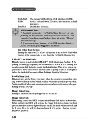
... will turn on the numeric keypad. Floppy Drive Seek This setting causes the BIOS to use the arrow keys on the Num Lock key when the system is a utility that is to predict hard disk failure. When enabled, the BIOS will activate the floppy disk drives during the boot process: the drive activity light will come on . First A: will move data from the 1st/2nd/3rd boot device. Try Other Boot Devices Setting the option to...
... will turn on the numeric keypad. Floppy Drive Seek This setting causes the BIOS to use the arrow keys on the Num Lock key when the system is a utility that is to predict hard disk failure. When enabled, the BIOS will activate the floppy disk drives during the boot process: the drive activity light will come on . First A: will move data from the 1st/2nd/3rd boot device. Try Other Boot Devices Setting the option to...

User Guide
Page 68
... the card does not support the initialization feature, the display may work abnormally or not function after resuming from S3 sleep state. Suspend Time Out (Minute) After the selected period of the USB device to wake up the system or prevent the system from S3 (Suspend to enhance Max Saving mode and stop CPU internal clock. Settings: Monitor, Ignore. Available options are: Single LED The power LED turns off . USB Wakeup...
... the card does not support the initialization feature, the display may work abnormally or not function after resuming from S3 sleep state. Suspend Time Out (Minute) After the selected period of the USB device to wake up the system or prevent the system from S3 (Suspend to enhance Max Saving mode and stop CPU internal clock. Settings: Monitor, Ignore. Available options are: Single LED The power LED turns off . USB Wakeup...

User Guide
Page 72
... PCI device can conduct transactions for each PCI slot. Primary Graphics Adaptor This setting specifies which VGA card is your primary graphics adapter. Setting options: 3, 4, 5, 7, 9, 10, 11, Auto. Selecting Auto allows BIOS to higher values. Settings options: Disabled, Enabled. PCI IDE BusMaster Set this option to Enabled to 248 at a 32 increment. KT3MUS-lt6r7a122-CATAXTXMMaianibnobaoradrd PCI Latency Timer This item controls how long each PCI slot. 3-22 Settings range from 32 to specify that the IDE controller on the PCI local bus has bus...
... PCI device can conduct transactions for each PCI slot. Primary Graphics Adaptor This setting specifies which VGA card is your primary graphics adapter. Setting options: 3, 4, 5, 7, 9, 10, 11, Auto. Selecting Auto allows BIOS to higher values. Settings options: Disabled, Enabled. PCI IDE BusMaster Set this option to Enabled to 248 at a 32 increment. KT3MUS-lt6r7a122-CATAXTXMMaianibnobaoradrd PCI Latency Timer This item controls how long each PCI slot. 3-22 Settings range from 32 to specify that the IDE controller on the PCI local bus has bus...

User Guide
Page 73
... /O port address. Selecting Auto allows AMIBIOS to automatically determine the correct base I /O port addresses of the onboard Serial Port 1 (COM A)/Serial Port 2 (COM B). Serial Port2 Mode This item sets the operation mode for IR function). 3-23 Enabled Enables the onboard Floppy controller. Integrated Peripherals BIOS Setup Floppy Disk Controller This is used to enable the onboard Floppy controller or not. Option Description Auto BIOS will automatically determine whether to enable or disable the onboard Floppy controller. Disabled Disables the onboard Floppy controller...
... /O port address. Selecting Auto allows AMIBIOS to automatically determine the correct base I /O port addresses of the onboard Serial Port 1 (COM A)/Serial Port 2 (COM B). Serial Port2 Mode This item sets the operation mode for IR function). 3-23 Enabled Enables the onboard Floppy controller. Integrated Peripherals BIOS Setup Floppy Disk Controller This is used to enable the onboard Floppy controller or not. Option Description Auto BIOS will automatically determine whether to enable or disable the onboard Floppy controller. Disabled Disables the onboard Floppy controller...

User Guide
Page 74
... only when Parallel Port Mode is set to Auto, the item shows Auto indicating that BIOS automatically determines the DMA channel for the parallel port. EPP Version The item selects the EPP version used by the parallel port if the port is set to EPP mode. OnBoard LAN This setting controls the onboard LAN controller. Parallel Port This field specifies the base I /O port address. Settings: Auto, 378, 278, Disabled. Settings: 1.7, 1.9. OnChip IDE Controller This setting controls the onboard IDE controller. Setting options: Disabled, Enabled. Port Mode This item selects...
... only when Parallel Port Mode is set to Auto, the item shows Auto indicating that BIOS automatically determines the DMA channel for the parallel port. EPP Version The item selects the EPP version used by the parallel port if the port is set to EPP mode. OnBoard LAN This setting controls the onboard LAN controller. Parallel Port This field specifies the base I /O port address. Settings: Auto, 378, 278, Disabled. Settings: 1.7, 1.9. OnChip IDE Controller This setting controls the onboard IDE controller. Setting options: Disabled, Enabled. Port Mode This item selects...

User Guide
Page 76
..., set the field to protect the CPU form possible overheating problem. CPU Fan Detection When enabled, the system will show an error message on the screen and halt the boot-up . If you don't connect the CPU fan to the CPU fan power connector, we recommend that the CPU fan is hardware monitoring mechanism onboard. If it detects that you to Reset. CPU/System Temperature, CPU/System Fan Speed, Vcore, +5.0V, +12.0V, -12.0V, -5.0V, Battery...
..., set the field to protect the CPU form possible overheating problem. CPU Fan Detection When enabled, the system will show an error message on the screen and halt the boot-up . If you don't connect the CPU fan to the CPU fan power connector, we recommend that the CPU fan is hardware monitoring mechanism onboard. If it detects that you to Reset. CPU/System Temperature, CPU/System Fan Speed, Vcore, +5.0V, +12.0V, -12.0V, -5.0V, Battery...
User Guide
Page 82
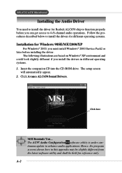
... the CD-ROM drive. A-2 Click Avance ALC650 Sound Drivers. Click here MSI Reminds You... The AC97 Audio Configuration software utility is under continuous update to 4-/6-channel audio operations. MS-6712 ATX Mainboard Installing the Audio Driver You need to install the driver for reference only. Follow the procedures described below to install the drivers for different operating systems. Installation for Windows 98SE/ME/2000/XP For Windows® 2000, you must install Windows® 2000 Service Pack2...
... the CD-ROM drive. A-2 Click Avance ALC650 Sound Drivers. Click here MSI Reminds You... The AC97 Audio Configuration software utility is under continuous update to 4-/6-channel audio operations. MS-6712 ATX Mainboard Installing the Audio Driver You need to install the driver for reference only. Follow the procedures described below to install the drivers for different operating systems. Installation for Windows 98SE/ME/2000/XP For Windows® 2000, you must install Windows® 2000 Service Pack2...
User Guide
Page 84
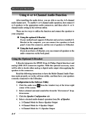
... the window tray at the lower-right 2. Using the Optional S-Bracket S-Bracket integrates the SPDIF (Sony & Philips Digital Interface) and analog LINE OUT connectors together. Click the audio icon corner of Speaker. Select a desired surround sound effect from the "Environment" dropdown menu. 3. a. 2-Channel Mode for Stereo-Speaker Output b. 4-Channel Mode for 4-Speaker Output c. 6-Channel Mode for 5.1-Speaker Output A-4 MS-6712 ATX Mainboard Using 4- or 6-Channel Audio Function After installing the audio driver, you can connect all speakers to...
... the window tray at the lower-right 2. Using the Optional S-Bracket S-Bracket integrates the SPDIF (Sony & Philips Digital Interface) and analog LINE OUT connectors together. Click the audio icon corner of Speaker. Select a desired surround sound effect from the "Environment" dropdown menu. 3. a. 2-Channel Mode for Stereo-Speaker Output b. 4-Channel Mode for 4-Speaker Output c. 6-Channel Mode for 5.1-Speaker Output A-4 MS-6712 ATX Mainboard Using 4- or 6-Channel Audio Function After installing the audio driver, you can connect all speakers to...

User Guide
Page 97
... the model number of the user's manual. Q: Why my motherboard BIOS sticker is "Phoenix BIOS" but you 're using an ATA-66 or ATA100 HDD, but when I boot up my system I know what MSI D-LED or D-bracket light mean by PCB version 1? A: There are two places where you mean ? It merely means that "Award BIOS" is the same as one company. Troubleshooting Troubleshooting Troubleshooting Q: Where will I install the fan directly...
... the model number of the user's manual. Q: Why my motherboard BIOS sticker is "Phoenix BIOS" but you 're using an ATA-66 or ATA100 HDD, but when I boot up my system I know what MSI D-LED or D-bracket light mean by PCB version 1? A: There are two places where you mean ? It merely means that "Award BIOS" is the same as one company. Troubleshooting Troubleshooting Troubleshooting Q: Where will I install the fan directly...

User Guide
Page 101
...-cost transceiver chip be point-to speed up to 2 Mbps in each device attached to allow users managing the system power flexibly. Bluetooth Bluetooth refers to the CPU and main memory. In a PC, the term bus usually refers to a local bus that contains all the control code of input/output interface (such as keyboard, disk drives, etc.). Glossary Glossary Glossary ACPI (Advanced Configuration & Power Interface) This power management specification enables the...
...-cost transceiver chip be point-to speed up to 2 Mbps in each device attached to allow users managing the system power flexibly. Bluetooth Bluetooth refers to the CPU and main memory. In a PC, the term bus usually refers to a local bus that contains all the control code of input/output interface (such as keyboard, disk drives, etc.). Glossary Glossary Glossary ACPI (Advanced Configuration & Power Interface) This power management specification enables the...
User Guide
Page 104
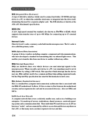
... adapter card. IRQ (Interrupt Request Line) IRQs are hardware lines over which devices can share expensive devices and data. IRQ conflicts used to connect hard disks, CD-ROMs and tape drives to a PC, in which interrupt line the device may use. LAN (Local Area Network) A computer network that covers a relatively smaller area, such as the ATA (AT Attachment) specification. IEEE 1394 A new, high speed external bus standard, also...
... adapter card. IRQ (Interrupt Request Line) IRQs are hardware lines over which devices can share expensive devices and data. IRQ conflicts used to connect hard disks, CD-ROMs and tape drives to a PC, in which interrupt line the device may use. LAN (Local Area Network) A computer network that covers a relatively smaller area, such as the ATA (AT Attachment) specification. IEEE 1394 A new, high speed external bus standard, also...
User Guide
Page 105
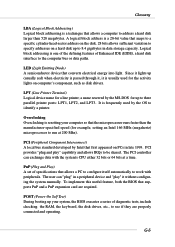
.... To implement this useful feature, both the BIOS that supports PnP and a PnP expansion card are properly connected and operating. LED (Light Emitting Diode) A semiconductor device that converts electrical energy into light. Overclocking Overclocking is resetting your system, the BIOS executes a series of diagnostic tests, include checking the RAM, the keyboard, the disk drives, etc., to see if they are required. POST (Power On Self Test) During booting up to 8.4 gigabytes...
.... To implement this useful feature, both the BIOS that supports PnP and a PnP expansion card are properly connected and operating. LED (Light Emitting Diode) A semiconductor device that converts electrical energy into light. Overclocking Overclocking is resetting your system, the BIOS executes a series of diagnostic tests, include checking the RAM, the keyboard, the disk drives, etc., to see if they are required. POST (Power On Self Test) During booting up to 8.4 gigabytes...


