User Guide
Page 4
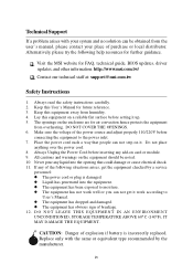
Visit the MSI website for future reference. 3. The openings on the equipment should be obtained from humidity. 4. Make sure the voltage of the power source and adjust properly ... ABOVE 600 C (1400F), IT MAY DAMAGE THE EQUIPMENT. Alternatively, please try the following situations arises, get it . Lay this User's Manual for FAQ, technical guide, BIOS updates, driver updates, and other information: http://www.msi.com.tw/ Contact our technical staff at: support...
Visit the MSI website for future reference. 3. The openings on the equipment should be obtained from humidity. 4. Make sure the voltage of the power source and adjust properly ... ABOVE 600 C (1400F), IT MAY DAMAGE THE EQUIPMENT. Alternatively, please try the following situations arises, get it . Lay this User's Manual for FAQ, technical guide, BIOS updates, driver updates, and other information: http://www.msi.com.tw/ Contact our technical staff at: support...
User Guide
Page 5
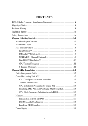
Getting Started 1-1 Mainboard Specifications 1-2 Mainboard Layout 1-4 MSI Special Features 1-5 Live Monitor 1-5 D-Bracket™ 2 (Optional 1-6 MSI DVD 5.1 Channel (Optional 1-8 LiveBIOS™/Live Driver 1-10 CPU Thermal Protection 1-11 S-Bracket (Optional 1-11 Chapter 2. CONTENTS FCC-B Radio ...for CPU 2-3 CPU Installation Procedures for Socket 462 2-4 Installing AMD Athlon CPU (Socket 462) Cooler Set 2-5 CPU Clock Frequency Selection through BIOS 2-6 Memory 2-7 Introduction to DDR SDRAM 2-7 DIMM Module Combination 2-8 Installing DDR Modules 2-8 Power Supply 2-9 v
Getting Started 1-1 Mainboard Specifications 1-2 Mainboard Layout 1-4 MSI Special Features 1-5 Live Monitor 1-5 D-Bracket™ 2 (Optional 1-6 MSI DVD 5.1 Channel (Optional 1-8 LiveBIOS™/Live Driver 1-10 CPU Thermal Protection 1-11 S-Bracket (Optional 1-11 Chapter 2. CONTENTS FCC-B Radio ...for CPU 2-3 CPU Installation Procedures for Socket 462 2-4 Installing AMD Athlon CPU (Socket 462) Cooler Set 2-5 CPU Clock Frequency Selection through BIOS 2-6 Memory 2-7 Introduction to DDR SDRAM 2-7 DIMM Module Combination 2-8 Installing DDR Modules 2-8 Power Supply 2-9 v

User Guide
Page 6
BIOS Setup 3-1 Entering Setup 3-2 vi ATX 20-Pin Power Connector: JWR1 2-9 Back Panel 2-10 Mouse Connector 2-10 Keyboard Connector 2-11 USB Connectors 2-11 Parallel Port Connector: LPT1 2-12 Audio Port Connectors 2-...
BIOS Setup 3-1 Entering Setup 3-2 vi ATX 20-Pin Power Connector: JWR1 2-9 Back Panel 2-10 Mouse Connector 2-10 Keyboard Connector 2-11 USB Connectors 2-11 Parallel Port Connector: LPT1 2-12 Audio Port Connectors 2-...
User Guide
Page 7
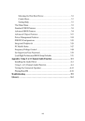
... Features 3-18 PNP/PCI Configurations 3-22 Integrated Peripherals 3-24 PC Health Status 3-27 Frequency/Voltage Control 3-28 Set Supervisor/User Password 3-30 Load High Performance/BIOS Setup Defaults 3-31 Appendix: Using 4- or 6-Channel Audio Function A-4 Testing the Connected Speakers A-14 Playing KaraOK A-16 Troubleshooting T-1 Glossary G-1 vii or 6-Channel Audio Function A-1 Installing...
... Features 3-18 PNP/PCI Configurations 3-22 Integrated Peripherals 3-24 PC Health Status 3-27 Frequency/Voltage Control 3-28 Set Supervisor/User Password 3-30 Load High Performance/BIOS Setup Defaults 3-31 Appendix: Using 4- or 6-Channel Audio Function A-4 Testing the Connected Speakers A-14 Playing KaraOK A-16 Troubleshooting T-1 Glossary G-1 vii or 6-Channel Audio Function A-1 Installing...

User Guide
Page 10
... (Rear * 4/ Front * 2) Audio † RealTek ALC650 6-channel audio LAN †VIA VT6103 LAN controller BIOS † The mainboard BIOS provides "Plug & Play" BIOS which detects the peripheral devices and expansion cards of the board automatically. † The mainboard provides a Desktop Management ...Interface (DMI) function which records your mainboard specifications. Dimension †ATX Form Factor: 30.5...
... (Rear * 4/ Front * 2) Audio † RealTek ALC650 6-channel audio LAN †VIA VT6103 LAN controller BIOS † The mainboard BIOS provides "Plug & Play" BIOS which detects the peripheral devices and expansion cards of the board automatically. † The mainboard provides a Desktop Management ...Interface (DMI) function which records your mainboard specifications. Dimension †ATX Form Factor: 30.5...

User Guide
Page 12
..., including the Search schedule. Provides a link to a database which contents various possible questions about MSI's products for the latest BIOS/drivers version on the screen. Double click the "MSI Live Monitor" icon at the lower-right corner of the taskbar, and the following dialog box will...Monitor™ application. Double click this icon to perform the functions z Auto Search - Getting Started MSI Special Features Live Monitor™ The Live Monitor™ is any. Searches for the BIOS/drivers version, or change the LAN settings right from the dialog box. z View Last Result -...
..., including the Search schedule. Provides a link to a database which contents various possible questions about MSI's products for the latest BIOS/drivers version on the screen. Double click the "MSI Live Monitor" icon at the lower-right corner of the taskbar, and the following dialog box will...Monitor™ application. Double click this icon to perform the functions z Auto Search - Getting Started MSI Special Features Live Monitor™ The Live Monitor™ is any. Searches for the BIOS/drivers version, or change the LAN settings right from the dialog box. z View Last Result -...

User Guide
Page 13
...the screen. 1-6 The D-LED will hang if the memory module is damaged or not installed properly. Initializing Keyboard Controller. Testing VGA BIOS - This will hang here if the processor is damaged or not installed properly. These users can detect all problems that fail the ...Chipset Initialization Memory Detection Test - The D-LED will start writing VGA sign-on message to debug the system. Testing onboard memory size. MS-6712 ATX Mainboard D-Bracket™ 2 (Optional) D-Bracket™ 2 is a USB bracket integrating four Diagnostic LEDs, which use the feature to help users...
...the screen. 1-6 The D-LED will hang if the memory module is damaged or not installed properly. Initializing Keyboard Controller. Testing VGA BIOS - This will hang here if the processor is damaged or not installed properly. These users can detect all problems that fail the ...Chipset Initialization Memory Detection Test - The D-LED will start writing VGA sign-on message to debug the system. Testing onboard memory size. MS-6712 ATX Mainboard D-Bracket™ 2 (Optional) D-Bracket™ 2 is a USB bracket integrating four Diagnostic LEDs, which use the feature to help users...

User Guide
Page 14
BIOS Sign On - Initializing Floppy Drive Controller - Operating System Booting 1-7 This will initialize IDE drive and controller. Testing Base and Extended Memory - This will show information ...
BIOS Sign On - Initializing Floppy Drive Controller - Operating System Booting 1-7 This will initialize IDE drive and controller. Testing Base and Extended Memory - This will show information ...
User Guide
Page 17
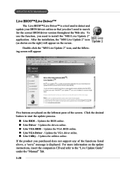
...of the functions listed above, a "sorry" message is a tool used to detect and update your BIOS/drivers online so that you don't need to start the update process. After the installation, the "MSI Live Update 2" icon (as shown on the right) will appear: Five buttons are placed on ...the update instructions, insert the companion CD and refer to search for the correct BIOS/driver version throughout the Web site. z Live Utility - MS-6712 ATX Mainboard Live BIOS™/Live Driver&#...
...of the functions listed above, a "sorry" message is a tool used to detect and update your BIOS/drivers online so that you don't need to start the update process. After the installation, the "MSI Live Update 2" icon (as shown on the right) will appear: Five buttons are placed on ...the update instructions, insert the companion CD and refer to search for the correct BIOS/driver version throughout the Web site. z Live Utility - MS-6712 ATX Mainboard Live BIOS™/Live Driver&#...
User Guide
Page 24
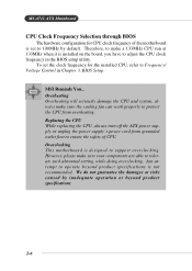
... We do not guarantee the damages or risks caused by default. BIOS Setup. Overclocking This motherboard is not recommended. Any attempt to operate beyond product specifications. 2-6 MS-6712 ATX Mainboard CPU Clock Frequency Selection through BIOS The hardware configuration for the installed CPU, refer to ensure the ...CPU and system, always make sure the cooling fan can work properly to tolerate such abnormal setting, while doing overclocking. MSI Reminds You... Therefore, to make sure your components are able to protect the CPU from grounded outlet first to Frequency/ Voltage ...
... We do not guarantee the damages or risks caused by default. BIOS Setup. Overclocking This motherboard is not recommended. Any attempt to operate beyond product specifications. 2-6 MS-6712 ATX Mainboard CPU Clock Frequency Selection through BIOS The hardware configuration for the installed CPU, refer to ensure the ...CPU and system, always make sure the cooling fan can work properly to tolerate such abnormal setting, while doing overclocking. MSI Reminds You... Therefore, to make sure your components are able to protect the CPU from grounded outlet first to Frequency/ Voltage ...

User Guide
Page 34
...you install two hard disks on cable, you must configure second hard drive to IDE1. IDE1 can also connect a Master and a Slave drive. MSI Reminds You... MS-6712 ATX Mainboard Hard Disk Connectors: IDE1 & IDE2 The mainboard has a 32-bit Enhanced PCI IDE and Ultra DMA 33/66/ 100/133 controller that... Master, and Ultra DMA 33/66/100/133 function. You can connect up to the hard disk documentation supplied by hard disk vendors for future BIOS) and other devices. You must configure the second drive to Slave mode by setting the jumper accordingly. Refer to four hard disk drives, CDROM,...
...you install two hard disks on cable, you must configure second hard drive to IDE1. IDE1 can also connect a Master and a Slave drive. MSI Reminds You... MS-6712 ATX Mainboard Hard Disk Connectors: IDE1 & IDE2 The mainboard has a 32-bit Enhanced PCI IDE and Ultra DMA 33/66/ 100/133 controller that... Master, and Ultra DMA 33/66/100/133 function. You can connect up to the hard disk documentation supplied by hard disk vendors for future BIOS) and other devices. You must configure the second drive to Slave mode by setting the jumper accordingly. Refer to four hard disk drives, CDROM,...

User Guide
Page 42
... a warning message on the screen. If the chassis is connected to a 2-pin chassis switch. You must enter the BIOS utility and clear the record. GND 2 CINTRU 1 JCI1 2-24 The system will be short. MS-6712 ATX Mainboard IrDA Infrared Module Header: JIR1 The connector allows you must configure the setting through the...
... a warning message on the screen. If the chassis is connected to a 2-pin chassis switch. You must enter the BIOS utility and clear the record. GND 2 CINTRU 1 JCI1 2-24 The system will be short. MS-6712 ATX Mainboard IrDA Infrared Module Header: JIR1 The connector allows you must configure the setting through the...

User Guide
Page 45
... The CNR slot allows you to insert the expansion cards to directly access main memory. It introduces a 66MHz, 32-bit channel for ATX family motherboards. PCI (Peripheral Component Interconnect) Slots The PCI slots allow you to insert the AGP graphics card. AGP is done through software and ... power supply first. Its main processing is an interface specification designed for the expansion card, such as jumpers, switches or BIOS configuration. Hardware Setup Slots The motherboard provides one AGP slot, six 32-bit PCI bus slots, and one CNR slot. Meanwhile, read the documentation for the...
... The CNR slot allows you to insert the expansion cards to directly access main memory. It introduces a 66MHz, 32-bit channel for ATX family motherboards. PCI (Peripheral Component Interconnect) Slots The PCI slots allow you to insert the AGP graphics card. AGP is done through software and ... power supply first. Its main processing is an interface specification designed for the expansion card, such as jumpers, switches or BIOS configuration. Hardware Setup Slots The motherboard provides one AGP slot, six 32-bit PCI bus slots, and one CNR slot. Meanwhile, read the documentation for the...

User Guide
Page 47
You may need to run the Setup program when: ” An error message appears on the BIOS Setup program and allows you to run SETUP. ” You want to configure the system for customized features. 3-1 BIOS Setup BIOS Setup This chapter provides information on the screen during the system booting up, and requests you to change the default settings for optimum use.
You may need to run the Setup program when: ” An error message appears on the BIOS Setup program and allows you to run SETUP. ” You want to configure the system for customized features. 3-1 BIOS Setup BIOS Setup This chapter provides information on the screen during the system booting up, and requests you to change the default settings for optimum use.
User Guide
Page 48
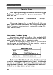
... Selecting the First Boot Device You are allowed to select the 1st boot device without entering the BIOS setup utility by turning it will still use the original first boot device to trigger the boot ...menu. The system will not make changes to the settings in time. MS-6712 ATX Mainboard Entering Setup Power on the computer and the system will list all the bootable devices. DEL...boot TAB:Logo If the message disappears before you respond and you still wish to respond in the BIOS setup utility, so next time when you to enter Setup, restart the system by pressing . The...
... Selecting the First Boot Device You are allowed to select the 1st boot device without entering the BIOS setup utility by turning it will still use the original first boot device to trigger the boot ...menu. The system will not make changes to the settings in time. MS-6712 ATX Mainboard Entering Setup Power on the computer and the system will list all the bootable devices. DEL...boot TAB:Logo If the message disappears before you respond and you still wish to respond in the BIOS setup utility, so next time when you to enter Setup, restart the system by pressing . The...

User Guide
Page 49
...the right-hand side Select the item Jumps to the Exit menu or returns to select the item. Default Settings The BIOS setup program contains two kinds of the screen. BIOS Setup defaults provide stable performance settings for the selected setup category is the Main Menu. You can use the arrow ... Load Optimized defaults Save all devices and the system, while High Performance defaults provide the best system performance but may affect the system stability. 3-3 BIOS Setup Control Keys Enter> Move to the previous item Move to the next item Move to the item on the left-hand side Move to...
...the right-hand side Select the item Jumps to the Exit menu or returns to select the item. Default Settings The BIOS setup program contains two kinds of the screen. BIOS Setup defaults provide stable performance settings for the selected setup category is the Main Menu. You can use the arrow ... Load Optimized defaults Save all devices and the system, while High Performance defaults provide the best system performance but may affect the system stability. 3-3 BIOS Setup Control Keys Enter> Move to the previous item Move to the next item Move to the item on the left-hand side Move to...
User Guide
Page 50
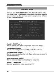
...Use this menu for power management. PNP/PCI Configurations This entry appears if your settings for basic system configurations, such as time, date etc. Advanced BIOS Features Use this menu to setup the items of AMI® special enhanced features. Advanced Chipset Features Use this menu to change the values in...performance. Standard CMOS Features Use this menu to enter the sub-menu. The Main Menu displays twelve configurable functions and two exit choices. MS-6712 ATX Mainboard The Main Menu Once you enter AMIBIOS NEW SETUP UTILITY, the Main Menu will appear on the screen.
...Use this menu for power management. PNP/PCI Configurations This entry appears if your settings for basic system configurations, such as time, date etc. Advanced BIOS Features Use this menu to setup the items of AMI® special enhanced features. Advanced Chipset Features Use this menu to change the values in...performance. Standard CMOS Features Use this menu to enter the sub-menu. The Main Menu displays twelve configurable functions and two exit choices. MS-6712 ATX Mainboard The Main Menu Once you enter AMIBIOS NEW SETUP UTILITY, the Main Menu will appear on the screen.

User Guide
Page 51
... Peripherals Use this menu to specify your settings for frequency/voltage control. Frequency/Voltage Control Use this menu to load the BIOS values for stable system performance operations. Set User Password Use this menu to specify your settings for integrated peripherals. Load High... to set User Password. Save & Exit Setup Save changes to load factory default settings into the BIOS for the best system performance, but the system stability may be affected. Load BIOS Setup Defaults Use this menu to set Supervisor Password. Exit Without Saving Abandon all changes and exit ...
... Peripherals Use this menu to specify your settings for frequency/voltage control. Frequency/Voltage Control Use this menu to load the BIOS values for stable system performance operations. Set User Password Use this menu to specify your settings for integrated peripherals. Load High... to set User Password. Save & Exit Setup Save changes to load factory default settings into the BIOS for the best system performance, but the system stability may be affected. Load BIOS Setup Defaults Use this menu to set Supervisor Password. Exit Without Saving Abandon all changes and exit ...

User Guide
Page 52
MS-6712 ATX Mainboard Standard CMOS Features The items inside STANDARD CMOS FEATURES menu are divided into 9 categories. Each category includes none, one or more setup items. Use ... time). date The date from 1 to the value you want to modify and use the or keys to switch to 31 can be keyed by BIOS. System Time This allows you to set the system to the date that you prefer. The specifi- 3-6 System Date This allows you want (usually the...
MS-6712 ATX Mainboard Standard CMOS Features The items inside STANDARD CMOS FEATURES menu are divided into 9 categories. Each category includes none, one or more setup items. Use ... time). date The date from 1 to the value you want to modify and use the or keys to switch to 31 can be keyed by BIOS. System Time This allows you to set the system to the date that you prefer. The specifi- 3-6 System Date This allows you want (usually the...

User Guide
Page 53
... of the HDD is to set the type of floppy drives installed. When Enabled, BIOS will issue a virus warning message and beep if a write to the boot sector or the partition table of hard disk drive will show up on ... write precomp cylinder Sectors Enter sector number Maximum Capacity Read the maximal HDD capacity LBA Mode Select Auto for IDE Hard Disk boot sector protection. MSI Reminds You... Modes mance by optimizing the hard disk timing 32 Bit Transfer Mode Enable 32 bit to maximize the IDE hard disk data transfer...
... of the HDD is to set the type of floppy drives installed. When Enabled, BIOS will issue a virus warning message and beep if a write to the boot sector or the partition table of hard disk drive will show up on ... write precomp cylinder Sectors Enter sector number Maximum Capacity Read the maximal HDD capacity LBA Mode Select Auto for IDE Hard Disk boot sector protection. MSI Reminds You... Modes mance by optimizing the hard disk timing 32 Bit Transfer Mode Enable 32 bit to maximize the IDE hard disk data transfer...


