User Guide
Page 4
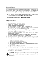
... following help resources for air convection hence protects the equipment from overheating. Always read the safety instructions carefully. 2. Technical Support If a problem arises with the same or equivalent type recommended by a service personnel: l The power cord or plug is incorrectly replaced. Keep this User's Manual for FAQ, technical guide, BIOS updates, driver updates, and other information: http://www.msi.com.tw/ Contact our technical staff at...
... following help resources for air convection hence protects the equipment from overheating. Always read the safety instructions carefully. 2. Technical Support If a problem arises with the same or equivalent type recommended by a service personnel: l The power cord or plug is incorrectly replaced. Keep this User's Manual for FAQ, technical guide, BIOS updates, driver updates, and other information: http://www.msi.com.tw/ Contact our technical staff at...
User Guide
Page 5
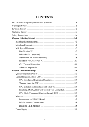
... Clock Frequency Selection through BIOS 2-6 Memory 2-7 Introduction to DDR SDRAM 2-7 DIMM Module Combination 2-8 Installing DDR Modules 2-8 Power Supply 2-9 v Getting Started 1-1 Mainboard Specifications 1-2 Mainboard Layout 1-4 MSI Special Features 1-5 Live Monitor 1-5 D-Bracket™ 2 (Optional 1-6 MSI DVD 5.1 Channel (Optional 1-8 LiveBIOS™/Live Driver 1-10 CPU Thermal Protection 1-11 S-Bracket (Optional 1-11 Chapter 2. CONTENTS FCC-B Radio Frequency Interference Statement ii Copyright Notice iii Revision History iii Technical Support iv Safety Instructions...
... Clock Frequency Selection through BIOS 2-6 Memory 2-7 Introduction to DDR SDRAM 2-7 DIMM Module Combination 2-8 Installing DDR Modules 2-8 Power Supply 2-9 v Getting Started 1-1 Mainboard Specifications 1-2 Mainboard Layout 1-4 MSI Special Features 1-5 Live Monitor 1-5 D-Bracket™ 2 (Optional 1-6 MSI DVD 5.1 Channel (Optional 1-8 LiveBIOS™/Live Driver 1-10 CPU Thermal Protection 1-11 S-Bracket (Optional 1-11 Chapter 2. CONTENTS FCC-B Radio Frequency Interference Statement ii Copyright Notice iii Revision History iii Technical Support iv Safety Instructions...
User Guide
Page 7
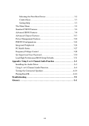
... Installing the Audio Driver A-2 Using 4- or 6-Channel Audio Function A-4 Testing the Connected Speakers A-14 Playing KaraOK A-16 Troubleshooting T-1 Glossary G-1 vii Selecting the First Boot Device 3-2 Control Keys 3-3 Getting Help 3-3 The Main Menu 3-4 Standard CMOS Features 3-6 Advanced BIOS Features 3-8 Advanced Chipset Features 3-13 Power Management Features 3-18 PNP/PCI Configurations 3-22 Integrated Peripherals 3-24 PC Health Status 3-27 Frequency/Voltage Control 3-28 Set Supervisor/User Password 3-30 Load High Performance/BIOS Setup Defaults 3-31 Appendix: Using...
... Installing the Audio Driver A-2 Using 4- or 6-Channel Audio Function A-4 Testing the Connected Speakers A-14 Playing KaraOK A-16 Troubleshooting T-1 Glossary G-1 vii Selecting the First Boot Device 3-2 Control Keys 3-3 Getting Help 3-3 The Main Menu 3-4 Standard CMOS Features 3-6 Advanced BIOS Features 3-8 Advanced Chipset Features 3-13 Power Management Features 3-18 PNP/PCI Configurations 3-22 Integrated Peripherals 3-24 PC Health Status 3-27 Frequency/Voltage Control 3-28 Set Supervisor/User Password 3-30 Load High Performance/BIOS Setup Defaults 3-31 Appendix: Using...
User Guide
Page 9
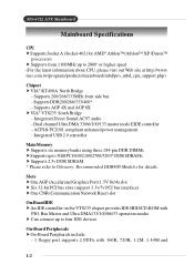
... USB 2.0 controller Main Memory † Supports six memory banks using three 184-pin DDR DIMMs † Supports up to four IDE devices On-Board Peripherals † On-Board Peripherals include: - 1 floppy port supports 2 FDDs with 360K, 720K, 1.2M, 1.44M and 1-2 Slots † One AGP (Accelerated Graphics Port) 1.5V 8x/4x slot † Six 32-bit PCI bus slots (support 3.3v/5v PCI bus interface) † One CNR (Communication Network Riser) slot On-Board IDE † An IDE controller on the VT8235 chipset provides IDE HDD/CD-ROM...
... USB 2.0 controller Main Memory † Supports six memory banks using three 184-pin DDR DIMMs † Supports up to four IDE devices On-Board Peripherals † On-Board Peripherals include: - 1 floppy port supports 2 FDDs with 360K, 720K, 1.2M, 1.44M and 1-2 Slots † One AGP (Accelerated Graphics Port) 1.5V 8x/4x slot † Six 32-bit PCI bus slots (support 3.3v/5v PCI bus interface) † One CNR (Communication Network Riser) slot On-Board IDE † An IDE controller on the VT8235 chipset provides IDE HDD/CD-ROM...
User Guide
Page 23
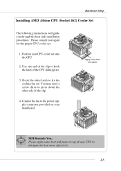
... Setup Installing AMD Athlon CPU (Socket 462) Cooler Set The following instructions will guide you through the heat sink installation procedures. Hook the other side of your mainboard. Apply some heat sink paste on your CPU to fix the cooling fan set. Please apply some heat sink paste MSI Reminds You... Connect the fan to hook the latch of the CPU sliding plate. 3. You may need a screw drive...
... Setup Installing AMD Athlon CPU (Socket 462) Cooler Set The following instructions will guide you through the heat sink installation procedures. Hook the other side of your mainboard. Apply some heat sink paste on your CPU to fix the cooling fan set. Please apply some heat sink paste MSI Reminds You... Connect the fan to hook the latch of the CPU sliding plate. 3. You may need a screw drive...
User Guide
Page 24
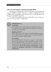
... make sure your components are able to support overclocking. Replacing the CPU While replacing the CPU, always turn off the ATX power supply or unplug the power supply's power cord from grounded outlet first to protect the CPU from overheating. MS-6712 ATX Mainboard CPU Clock Frequency Selection through BIOS The hardware configuration for the installed CPU, refer to 100MHz by inadequate operation or beyond product specifications is not recommended. To set to Frequency/ Voltage Control in the BIOS setup utility.
... make sure your components are able to support overclocking. Replacing the CPU While replacing the CPU, always turn off the ATX power supply or unplug the power supply's power cord from grounded outlet first to protect the CPU from overheating. MS-6712 ATX Mainboard CPU Clock Frequency Selection through BIOS The hardware configuration for the installed CPU, refer to 100MHz by inadequate operation or beyond product specifications is not recommended. To set to Frequency/ Voltage Control in the BIOS setup utility.

User Guide
Page 45
... directly access main memory. When adding or removing expansion cards, make any necessary hardware or software settings for the graphics controller to insert the AGP graphics card. Hardware Setup Slots The motherboard provides one AGP slot, six 32-bit PCI bus slots, and one CNR slot. AGP is an interface specification designed for ATX family motherboards. CNR (Communication Network Riser) Slot The CNR slot allows you unplug the power supply first. CNR is done through software and controlled by the motherboard's chipset...
... directly access main memory. When adding or removing expansion cards, make any necessary hardware or software settings for the graphics controller to insert the AGP graphics card. Hardware Setup Slots The motherboard provides one AGP slot, six 32-bit PCI bus slots, and one CNR slot. AGP is an interface specification designed for ATX family motherboards. CNR (Communication Network Riser) Slot The CNR slot allows you unplug the power supply first. CNR is done through software and controlled by the motherboard's chipset...
User Guide
Page 56
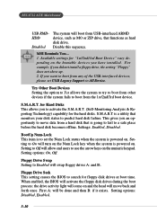
... set USB Legacy Support to boot from USB-interfaced ARMD device, such as MO or ZIP drive, that monitors your disk status to predict hard disk failure. Try Other Boot Devices Setting the option to Yes allows the system to try to boot from other devices if the system fails to All Device. Floppy Drive Swap Setting to search for "1st/2nd/3rd Boot Device" vary depending on . When enabled, the BIOS will activate the floppy disk drives during the boot...
... set USB Legacy Support to boot from USB-interfaced ARMD device, such as MO or ZIP drive, that monitors your disk status to predict hard disk failure. Try Other Boot Devices Setting the option to Yes allows the system to try to boot from other devices if the system fails to All Device. Floppy Drive Swap Setting to search for "1st/2nd/3rd Boot Device" vary depending on . When enabled, the BIOS will activate the floppy disk drives during the boot...
User Guide
Page 65
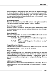
... you to indicate the sleep/suspend state. Power Management/APM Setting to RAM) sleep state. Settings: Disabled, Enabled. Available options are: Single LED The power LED turns off . Settings: Disabled, 1, 2, 4, 8, 10, 20, 30, 40, 50, 60. Therefore, if the AGP driver of the USB device to initialize the VGA card. USB Wakeup From S3 This item allows the activity of the card does not support the initialization feature, the display may work abnormally or not...
... you to indicate the sleep/suspend state. Power Management/APM Setting to RAM) sleep state. Settings: Disabled, Enabled. Available options are: Single LED The power LED turns off . Settings: Disabled, 1, 2, 4, 8, 10, 20, 30, 40, 50, 60. Therefore, if the AGP driver of the USB device to initialize the VGA card. USB Wakeup From S3 This item allows the activity of the card does not support the initialization feature, the display may work abnormally or not...

User Guide
Page 69
... IRQ line for each PCI slot. PCI IDE BusMaster Set this option to Enabled to 248 at a 32 increment. Primary Graphics Adaptor This setting specifies which VGA card is your primary graphics adapter. Settings options: Disabled, Enabled. Setting options: 3, 4, 5, 7, 9, 10, 11, Auto. Selecting Auto allows BIOS to higher values. Setting options: PCI, AGP. When set the item to automatically determine the IRQ line for each PCI slot. 3-23 BIOS Setup PCI Latency Timer This item controls how long each PCI device can conduct transactions...
... IRQ line for each PCI slot. PCI IDE BusMaster Set this option to Enabled to 248 at a 32 increment. Primary Graphics Adaptor This setting specifies which VGA card is your primary graphics adapter. Settings options: Disabled, Enabled. Setting options: 3, 4, 5, 7, 9, 10, 11, Auto. Selecting Auto allows BIOS to higher values. Setting options: PCI, AGP. When set the item to automatically determine the IRQ line for each PCI slot. 3-23 BIOS Setup PCI Latency Timer This item controls how long each PCI device can conduct transactions...

User Guide
Page 70
Option Description Auto BIOS will automatically determine whether to enable or disable the onboard Floppy controller. Enabled Enables the onboard Floppy controller. Settings: Auto, 3F8/ COM1, 2F8/COM2, 3E8/COM3, 2E8/COM4 and Disabled. Disabled Disables the onboard Floppy controller. Serial Port2 Mode This item sets the operation mode for IR function). 3-24 Serial Port 1/2 These items specify the base I /O port address. MS-6712 ATX Mainboard Integrated Peripherals Floppy Disk Controller This is used to enable the onboard Floppy controller or not. Settings: Normal, 1.6 ...
Option Description Auto BIOS will automatically determine whether to enable or disable the onboard Floppy controller. Enabled Enables the onboard Floppy controller. Settings: Auto, 3F8/ COM1, 2F8/COM2, 3E8/COM3, 2E8/COM4 and Disabled. Disabled Disables the onboard Floppy controller. Serial Port2 Mode This item sets the operation mode for IR function). 3-24 Serial Port 1/2 These items specify the base I /O port address. MS-6712 ATX Mainboard Integrated Peripherals Floppy Disk Controller This is used to enable the onboard Floppy controller or not. Settings: Normal, 1.6 ...

User Guide
Page 71
... the power saving modes through any event on PME (Power Management Event). OnBoard LAN This setting controls the onboard LAN controller. Setting options: Disabled, Enabled. 3-25 Set to automatically determine the correct base I /O port address of the onboard parallel port. Selecting Auto allows AMIBIOS to SINB/SOUTB. Port IRQ When OnBoard Parallel Port is set to the IR header. BIOS Setup IR Pin Select Set to IRRX/IRTX when using an internal IR module connected to Auto, the item shows Auto indicating that BIOS...
... the power saving modes through any event on PME (Power Management Event). OnBoard LAN This setting controls the onboard LAN controller. Setting options: Disabled, Enabled. 3-25 Set to automatically determine the correct base I /O port address of the onboard parallel port. Selecting Auto allows AMIBIOS to SINB/SOUTB. Port IRQ When OnBoard Parallel Port is set to the IR header. BIOS Setup IR Pin Select Set to IRRX/IRTX when using an internal IR module connected to Auto, the item shows Auto indicating that BIOS...

User Guide
Page 73
... CPU fan is built with CPU fan power connector (CFAN1) only and enables you disable the feature. The setting of the monitored hardware devices/components such as CPU voltages, temperatures and all of the field will show an error message on the screen and halt the boot-up . CPU/System Temperature, CPU/System Fan Speed, Vcore, +5.0V, +12.0V, -12.0V, -5.0V, Battery, +5V SB These items display the current status of all fans' speeds. 3-27 BIOS Setup...
... CPU fan is built with CPU fan power connector (CFAN1) only and enables you disable the feature. The setting of the monitored hardware devices/components such as CPU voltages, temperatures and all of the field will show an error message on the screen and halt the boot-up . CPU/System Temperature, CPU/System Fan Speed, Vcore, +5.0V, +12.0V, -12.0V, -5.0V, Battery, +5V SB These items display the current status of all fans' speeds. 3-27 BIOS Setup...
User Guide
Page 79
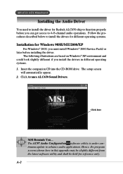
... be slightly different from the latest software utility and shall be held for reference only. Click Avance ALC650 Sound Drivers. Click here MSI Reminds You... MS-6712 ATX Mainboard Installing the Audio Driver You need to install the driver for Realtek ALC650 chip to function properly before installing the driver. The AC97 Audio Configuration software utility is under continuous update to enhance audio applications. The setup screen will automatically appear. 2. Hence, the program...
... be slightly different from the latest software utility and shall be held for reference only. Click Avance ALC650 Sound Drivers. Click here MSI Reminds You... MS-6712 ATX Mainboard Installing the Audio Driver You need to install the driver for Realtek ALC650 chip to function properly before installing the driver. The AC97 Audio Configuration software utility is under continuous update to enhance audio applications. The setup screen will automatically appear. 2. Hence, the program...
User Guide
Page 81
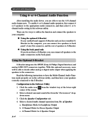
... audio icon corner of Speaker. Select a desired multi-channel operation from the "Environment" dropdown menu. 3. of the screen. To enable 4- or 6-channel audio operation, first connect 4 or 6 speakers to the connectors. Select a desired surround sound effect from No. a. Headphones Mode for headphone Output b. 2-Channel Mode for Stereo-Speaker Output c. 4-Channel Mode for 4-Speaker Output A-4 Read the following instructions to have the Multi-Channel Audio Function mode properly set in the software utility, and then have your motherboard supports...
... audio icon corner of Speaker. Select a desired multi-channel operation from the "Environment" dropdown menu. 3. of the screen. To enable 4- or 6-channel audio operation, first connect 4 or 6 speakers to the connectors. Select a desired surround sound effect from No. a. Headphones Mode for headphone Output b. 2-Channel Mode for Stereo-Speaker Output c. 4-Channel Mode for 4-Speaker Output A-4 Read the following instructions to have the Multi-Channel Audio Function mode properly set in the software utility, and then have your motherboard supports...
User Guide
Page 97
.../support/manual/mnu/spt_mnu_list.php? For Server motherboard, refer to chipset, on-board LAN, on-board VGA, on-board audio, on-board IDE, on-board SCSI & etc. 2. kind=2&CHIP=Archives&ID=4 & find your place for new BIOS chip http://www.msi.com.tw/contact/main.htm Q: Should I find your card under the Geforce4 area If in http://www.msi.com.tw/support/bios/boot.htm 2. For VGA card, refer to the chipset type 2. Try to clear the CMOS If problem...
.../support/manual/mnu/spt_mnu_list.php? For Server motherboard, refer to chipset, on-board LAN, on-board VGA, on-board audio, on-board IDE, on-board SCSI & etc. 2. kind=2&CHIP=Archives&ID=4 & find your place for new BIOS chip http://www.msi.com.tw/contact/main.htm Q: Should I find your card under the Geforce4 area If in http://www.msi.com.tw/support/bios/boot.htm 2. For VGA card, refer to the chipset type 2. Try to clear the CMOS If problem...

User Guide
Page 100
A: Suggestions Remove all the unnecessary devices & try to find the source of motherboard? Troubleshooting Q: What should I do if my MSI VGA card have compatibility issue with another brand of the problem Disable all on-board device like audio, RAID or others apply & see if it is due to resource conflict Move the PCI card to different PCI slots Update the card BIOS or drivers Update the motherboard BIOS Q: What should I do if my motherboard have compatibility issue with PCI cards? A: Update the video driver Update the motherboard driver or BIOS T-7
A: Suggestions Remove all the unnecessary devices & try to find the source of motherboard? Troubleshooting Q: What should I do if my MSI VGA card have compatibility issue with another brand of the problem Disable all on-board device like audio, RAID or others apply & see if it is due to resource conflict Move the PCI card to different PCI slots Update the card BIOS or drivers Update the motherboard BIOS Q: What should I do if my motherboard have compatibility issue with PCI cards? A: Update the video driver Update the motherboard driver or BIOS T-7

User Guide
Page 101
... Graphics Port) A new, high-speed graphics interface that a low-cost transceiver chip be exchanged at a rate of 1 megabit per second (up to 2 Mbps in the second generation of the technology). In addition to data, up the data transfer. Data can be included in a ROM chip. BIOS (Basic Input/Output System) On PCs, an essential software that connects the internal components to the CPU and main memory...
... Graphics Port) A new, high-speed graphics interface that a low-cost transceiver chip be exchanged at a rate of 1 megabit per second (up to 2 Mbps in the second generation of the technology). In addition to data, up the data transfer. Data can be included in a ROM chip. BIOS (Basic Input/Output System) On PCs, an essential software that connects the internal components to the CPU and main memory...

User Guide
Page 104
... microprocessor. When you add a new device to a PC, you to transfer data from one device to be a common problem when adding expansion boards, but the Plug-and-Play specification has removed this headache in most cases. MS-6712 ATX Mainboard IDE (Integrated Drive Electronics) A type of disk-drive interface widely used to another without any cables. Internal Cache Short for transmitting data via infrared light waves. Also see EISA and...
... microprocessor. When you add a new device to a PC, you to transfer data from one device to be a common problem when adding expansion boards, but the Plug-and-Play specification has removed this headache in most cases. MS-6712 ATX Mainboard IDE (Integrated Drive Electronics) A type of disk-drive interface widely used to another without any cables. Internal Cache Short for transmitting data via infrared light waves. Also see EISA and...
User Guide
Page 105
... device name for the activity lights on computer's component, such as disk drivers. a name reserved by Intel that allows a PC to configure itself automatically to work with the system's CPU either 32 bits or 64 bits at 200 Mhz). PnP (Plug and Play) A set of Enhanced IDE (EIDE), a hard disk interface to the computer bus or data paths. Overclocking Overclocking is one of the defining features of specifications...
... device name for the activity lights on computer's component, such as disk drivers. a name reserved by Intel that allows a PC to configure itself automatically to work with the system's CPU either 32 bits or 64 bits at 200 Mhz). PnP (Plug and Play) A set of Enhanced IDE (EIDE), a hard disk interface to the computer bus or data paths. Overclocking Overclocking is one of the defining features of specifications...


