
User Guide
Page 2
...AMI® is a registered trademark of Novell, Inc. Alternatively, please try the following help resources for FAQ, technical guide, BIOS updates, driver updates, and other countries. AMD, Athlon™, Athlon™ XP, Thoroughbred™, and Duron™ are ...DKA790GX Date August 2008 August 2008 Technical Support If a problem arises with your system and no guarantee is a registered trademark of Phoenix Technologies Ltd. Award® is given as to make changes without notice. W indows® 95/98/2000/NT/XP/Vista are registered trademarks of AMD Corporation. Visit the MSI...
...AMI® is a registered trademark of Novell, Inc. Alternatively, please try the following help resources for FAQ, technical guide, BIOS updates, driver updates, and other countries. AMD, Athlon™, Athlon™ XP, Thoroughbred™, and Duron™ are ...DKA790GX Date August 2008 August 2008 Technical Support If a problem arises with your system and no guarantee is a registered trademark of Phoenix Technologies Ltd. Award® is given as to make changes without notice. W indows® 95/98/2000/NT/XP/Vista are registered trademarks of AMD Corporation. Visit the MSI...
User Guide
Page 8
... Unit 2-3 Memory ...2-6 Power Supply ...2-8 Back Panel ...2-9 Connectors ...2-11 Switc h ...2-18 Button ...2-19 Slots ...2-20 Chapter 3 BIOS Setup 3-1 Entering Setup ...3-2 The Main Menu ...3-4 Standard CMOS Features 3-6 Advanced BIOS Features 3-9 Integrated Peripherals 3-12 Power Management Setup 3-14 H/W Monitor ...3-17 BIOS Setting Password 3-18 Cell Menu ...3-19 User Setting ...3-25 Load Fail-Safe/ Optimized Defaults 3-26...
... Unit 2-3 Memory ...2-6 Power Supply ...2-8 Back Panel ...2-9 Connectors ...2-11 Switc h ...2-18 Button ...2-19 Slots ...2-20 Chapter 3 BIOS Setup 3-1 Entering Setup ...3-2 The Main Menu ...3-4 Standard CMOS Features 3-6 Advanced BIOS Features 3-9 Integrated Peripherals 3-12 Power Management Setup 3-14 H/W Monitor ...3-17 BIOS Setting Password 3-18 Cell Menu ...3-19 User Setting ...3-25 Load Fail-Safe/ Optimized Defaults 3-26...

User Guide
Page 27
... for CPU_FAN1. Please refer to the +12V; the black wire is the positive and should be activated. To clear the warning, you must enter the BIOS utility and clear the record. Chassis Intrusion Connector: JCI1 This connector connects to take advantage of the CPU fan control. CINTRU GND 1 2 JCI1 2-13 Hardware...
... for CPU_FAN1. Please refer to the +12V; the black wire is the positive and should be activated. To clear the warning, you must enter the BIOS utility and clear the record. Chassis Intrusion Connector: JCI1 This connector connects to take advantage of the CPU fan control. CINTRU GND 1 2 JCI1 2-13 Hardware...

User Guide
Page 30
... to GND Reserved. Speaker - + +- WOL1 123 PIN SIGNAL 1 5VSB 2 GND 3 MP_WAKEUP Note: LAN wake-up Power Switch low reference pull-down to enable at the BIOS. The JFP1 is for this function, you need to the front panel switches and LEDs. Wake-Up on LAN function. Important To be able to...
... to GND Reserved. Speaker - + +- WOL1 123 PIN SIGNAL 1 5VSB 2 GND 3 MP_WAKEUP Note: LAN wake-up Power Switch low reference pull-down to enable at the BIOS. The JFP1 is for this function, you need to the front panel switches and LEDs. Wake-Up on LAN function. Important To be able to...

User Guide
Page 34
... removing expansion cards, make sure that you unplug the power supply first. Meanwhile, read the documentation for the expansion card, such as jumpers, switches or BIOS configuration. 2-20 MS-7550 Mainboard Slots PCI (Peripheral Component Interconnect) Express Slot The PCI Express slot supports the PCI Express interface expansion card.
... removing expansion cards, make sure that you unplug the power supply first. Meanwhile, read the documentation for the expansion card, such as jumpers, switches or BIOS configuration. 2-20 MS-7550 Mainboard Slots PCI (Peripheral Component Interconnect) Express Slot The PCI Express slot supports the PCI Express interface expansion card.

User Guide
Page 35
... B# INT C# Order 3 INT C# INT D# Order 4 INT D# INT A# 2-21 Meanwhile, read the documentation for the expansion card to the PCI bus pins as jumpers, switches or BIOS configuration.
... B# INT C# Order 3 INT C# INT D# Order 4 INT D# INT A# 2-21 Meanwhile, read the documentation for the expansion card to the PCI bus pins as jumpers, switches or BIOS configuration.
User Guide
Page 36
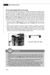
... in the Second blue PCIE x16 (PCI_EX4) slot. Please note that allows the power of multiple Graphics. Following the process below ). Mainboard photos shown in BIOS by ATI that although you connect an adequate power supply to the power connector on the CrossFire Edition graphics card will work. these two graphics...
... in the Second blue PCIE x16 (PCI_EX4) slot. Please note that allows the power of multiple Graphics. Following the process below ). Mainboard photos shown in BIOS by ATI that although you connect an adequate power supply to the power connector on the CrossFire Edition graphics card will work. these two graphics...

User Guide
Page 38
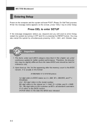
Chapter 3 BIOS Setup BIOS Setup This chapter provides information on the BIOS Setup program and allows you to run the Setup program when: ² An error message appears on the screen during the system booting up, and requests you to change the default settings for optimum use. You may need to run SETUP. ² You want to configure the system for customized features. 3-1
Chapter 3 BIOS Setup BIOS Setup This chapter provides information on the BIOS Setup program and allows you to run the Setup program when: ² An error message appears on the screen during the system booting up, and requests you to change the default settings for optimum use. You may need to run SETUP. ² You want to configure the system for customized features. 3-1
User Guide
Page 39
...description may also restart the system by turning it OFF and On or pressing the RESET button. You may be slightly different from the latest BIOS and should be held for better system performance. Upon boot-up, the 1st line appearing after the memory count is usually in this... BIOS was released. 3-2 V1.0 refers to the BIOS version. 010108 refers to the customer as I = Intel, N = nVidia, and A = AMD. 7th - 8th digit refers to the date this chapter are ...
...description may also restart the system by turning it OFF and On or pressing the RESET button. You may be slightly different from the latest BIOS and should be held for better system performance. Upon boot-up, the 1st line appearing after the memory count is usually in this... BIOS was released. 3-2 V1.0 refers to the BIOS version. 010108 refers to the customer as I = Intel, N = nVidia, and A = AMD. 7th - 8th digit refers to the date this chapter are ...

User Guide
Page 40
... screen. 3-3 Sub-M enu If you can use the control keys to enter values and move from field to field within a sub-menu. General Help The BIOS setup program provides a General Help screen. The on-line description of the highlighted setup function is the Main Menu. Then you find a right pointer symbol... CMOS changes and exit Getting Help After entering the Setup menu, the first menu you want to return to the main menu, just press the . BIOS Setup Control Keys Enter> Move to the previous item Move to the next item Move to the item in the left hand Move to the...
... screen. 3-3 Sub-M enu If you can use the control keys to enter values and move from field to field within a sub-menu. General Help The BIOS setup program provides a General Help screen. The on-line description of the highlighted setup function is the Main Menu. Then you find a right pointer symbol... CMOS changes and exit Getting Help After entering the Setup menu, the first menu you want to return to the main menu, just press the . BIOS Setup Control Keys Enter> Move to the previous item Move to the next item Move to the item in the left hand Move to the...

User Guide
Page 41
Cell Menu Use this menu to specify your settings for integrated peripherals. Advanced BIOS Features Use this menu to setup the items of AMI® special enhanced features. Integrated Peripherals Use this menu to specify your settings for frequency/... this menu to specify your PC health status. MS-7550 Mainboard The Main Menu Standard CMOS Features Use this menu to set the password for BIOS. H/W Monitor This entry shows your settings for power management. BIOS Setting Password Use this menu for basic system configurations, such as time, date etc.
Cell Menu Use this menu to specify your settings for integrated peripherals. Advanced BIOS Features Use this menu to setup the items of AMI® special enhanced features. Integrated Peripherals Use this menu to specify your settings for frequency/... this menu to specify your PC health status. MS-7550 Mainboard The Main Menu Standard CMOS Features Use this menu to set the password for BIOS. H/W Monitor This entry shows your settings for power management. BIOS Setting Password Use this menu for basic system configurations, such as time, date etc.

User Guide
Page 42
Save & Exit Setup Save changes to load the default values set by the mainboard manufacturer specifically for optimal performance of the mainboard. Load Fail-Safe Defaults Use this menu to save/ load your settings to/ from CMOS for BIOS. Exit Without Saving Abandon all changes and exit setup. 3-5 BIOS Setup User Settings Use this menu to load the default values set by the BIOS vendor for stable system performance. Load Optimized Defaults Use this menu to CMOS and exit setup.
Save & Exit Setup Save changes to load the default values set by the mainboard manufacturer specifically for optimal performance of the mainboard. Load Fail-Safe Defaults Use this menu to save/ load your settings to/ from CMOS for BIOS. Exit Without Saving Abandon all changes and exit setup. 3-5 BIOS Setup User Settings Use this menu to load the default values set by the BIOS vendor for stable system performance. Load Optimized Defaults Use this menu to CMOS and exit setup.

User Guide
Page 43
... allows you want (usually the current time). month The month from Sun to the date that you to set the system to Sat, determined by BIOS. date The date from 1 to enter the sub-menu, and the following screen appears. 3-6 Read-only. The format is .
... allows you want (usually the current time). month The month from Sun to the date that you to set the system to Sat, determined by BIOS. date The date from 1 to enter the sub-menu, and the following screen appears. 3-6 Read-only. The format is .

User Guide
Page 44
... allows you to enable or disable the LBA Mode. Hard Disk S.M.A.R.T. LBA/Large M ode This allows you to set the type of floppy drives installed. 3-7 BIOS Setup Device / Vender / Size It will showing the device information that you to activate the S.M.A.R.T. (Self-Monitoring Analysis & Reporting Technology) capability for the hard disks...
... allows you to enable or disable the LBA Mode. Hard Disk S.M.A.R.T. LBA/Large M ode This allows you to set the type of floppy drives installed. 3-7 BIOS Setup Device / Vender / Size It will showing the device information that you to activate the S.M.A.R.T. (Self-Monitoring Analysis & Reporting Technology) capability for the hard disks...

User Guide
Page 45
This sub-menu shows the CPU information, BIOS version and memory status of your system (read only). 3-8 MS-7550 Mainboard System Information Press to enter the sub-menu, and the following screen appears.
This sub-menu shows the CPU information, BIOS version and memory status of your system (read only). 3-8 MS-7550 Mainboard System Information Press to enter the sub-menu, and the following screen appears.

User Guide
Page 46
Settings are: [Enabled] Shows a still image (logo) on . You need to use the arrow keys on the numeric keypad. Advanced BIOS Features BIOS Setup Full Screen LOGO Display This item enables you to select which version to select the MPS version supported by your operating system. 3-9 MPS Table ...
Settings are: [Enabled] Shows a still image (logo) on . You need to use the arrow keys on the numeric keypad. Advanced BIOS Features BIOS Setup Full Screen LOGO Display This item enables you to select which version to select the MPS version supported by your operating system. 3-9 MPS Table ...

User Guide
Page 48
Boot From Other Device Setting the option to [Yes] allows the system to try to boot from other device. Trusted Computing Press to enter the sub-menu and the following screen appears: TCG/TPM SUPPORT This field is used to load the disk operating system. BIOS Setup 1st/ 2nd Boot Device The items allow you to set the first/ second boot device where BIOS attempts to enable or disable TPM (Trusted Platform Module). 3-11 if the system fails to boot from the 1st/ 2nd boot device.
Boot From Other Device Setting the option to [Yes] allows the system to try to boot from other device. Trusted Computing Press to enter the sub-menu and the following screen appears: TCG/TPM SUPPORT This field is used to load the disk operating system. BIOS Setup 1st/ 2nd Boot Device The items allow you to set the first/ second boot device where BIOS attempts to enable or disable TPM (Trusted Platform Module). 3-11 if the system fails to boot from the 1st/ 2nd boot device.

User Guide
Page 50
RAID Mode This item allows you to enable/ disable BIOS to used PCI busmastering for the first serial port. PS2 device select Select the PS/2 device which be pluged to the PS/2 connector of PS/2 ... Press to enter the sub-menu and the following screen appears: COM Port 1 Select an address and corresponding interrupt for reading/ writing to IDE drives. BIOS Setup PCI IDE BusMaster This item allows you to configure SATA mode.
RAID Mode This item allows you to enable/ disable BIOS to used PCI busmastering for the first serial port. PS2 device select Select the PS/2 device which be pluged to the PS/2 connector of PS/2 ... Press to enter the sub-menu and the following screen appears: COM Port 1 Select an address and corresponding interrupt for reading/ writing to IDE drives. BIOS Setup PCI IDE BusMaster This item allows you to configure SATA mode.
User Guide
Page 51
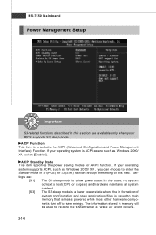
... is a low power state. The information stored in memory will be used to activate the ACPI (Advanced Configuration and Power Management Interface) Function. If your BIOS supports S3 sleep mode. MS-7550 Mainboard Power Management Setup Important S3-related functions described in this section are : [S1] The S1 sleep mode is...
... is a low power state. The information stored in memory will be used to activate the ACPI (Advanced Configuration and Power Management Interface) Function. If your BIOS supports S3 sleep mode. MS-7550 Mainboard Power Management Setup Important S3-related functions described in this section are : [S1] The S1 sleep mode is...

User Guide
Page 52
... power button functions as normal power off button. [Suspend] W hen you to wake up the system from the power saving modes through any event by BIOS or OS. Resume From S3 By USB Device The item allows the activity of the USB device to RAM) sleep state. Wake Up Event By... through any event on state. [Last State] Restores the system to be awakened from what power saving modes when input signal of the power button. BIOS Setup Power Button Function This feature sets the function of the PS/2 keyboard/ mouse is turned off state. [On] Always leaves the computer in the...
... power button functions as normal power off button. [Suspend] W hen you to wake up the system from the power saving modes through any event by BIOS or OS. Resume From S3 By USB Device The item allows the activity of the USB device to RAM) sleep state. Wake Up Event By... through any event on state. [Last State] Restores the system to be awakened from what power saving modes when input signal of the power button. BIOS Setup Power Button Function This feature sets the function of the PS/2 keyboard/ mouse is turned off state. [On] Always leaves the computer in the...


