
User Guide
Page 2
...DKA790GX Platinum For DKA790GX Date August 2008 August 2008 Technical Support If a problem arises with your place of purchase or local distributor. func=service Contact our technical staff at: http://ocss.msi.com.tw ii Copyright Notice The material in this document, but no solution can be obtained from the user's manual...trademark of Phoenix Technologies Ltd. Alternatively, please try the following help resources for FAQ, technical guide, BIOS updates, driver updates, and other countries. Intel® and Pentium® are registered trademarks of Intel Corporation. AMD, Athlon™...
...DKA790GX Platinum For DKA790GX Date August 2008 August 2008 Technical Support If a problem arises with your place of purchase or local distributor. func=service Contact our technical staff at: http://ocss.msi.com.tw ii Copyright Notice The material in this document, but no solution can be obtained from the user's manual...trademark of Phoenix Technologies Ltd. Alternatively, please try the following help resources for FAQ, technical guide, BIOS updates, driver updates, and other countries. Intel® and Pentium® are registered trademarks of Intel Corporation. AMD, Athlon™...
User Guide
Page 8
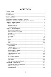
... Unit 2-3 Memory ...2-6 Power Supply ...2-8 Back Panel ...2-9 Connectors ...2-11 Switc h ...2-18 Button ...2-19 Slots ...2-20 Chapter 3 BIOS Setup 3-1 Entering Setup ...3-2 The Main Menu ...3-4 Standard CMOS Features 3-6 Advanced BIOS Features 3-9 Integrated Peripherals 3-12 Power Management Setup 3-14 H/W Monitor ...3-17 BIOS Setting Password 3-18 Cell Menu ...3-19 User Setting ...3-25 Load Fail-Safe/ Optimized Defaults 3-26 Appendix A Realtek Audio A-1 Installing the Realtek HD Audio Driver A-2 Software Configuration A-4 Hardware Setup A-19 viii Getting Started 1-1 Mainboard...
... Unit 2-3 Memory ...2-6 Power Supply ...2-8 Back Panel ...2-9 Connectors ...2-11 Switc h ...2-18 Button ...2-19 Slots ...2-20 Chapter 3 BIOS Setup 3-1 Entering Setup ...3-2 The Main Menu ...3-4 Standard CMOS Features 3-6 Advanced BIOS Features 3-9 Integrated Peripherals 3-12 Power Management Setup 3-14 H/W Monitor ...3-17 BIOS Setting Password 3-18 Cell Menu ...3-19 User Setting ...3-25 Load Fail-Safe/ Optimized Defaults 3-26 Appendix A Realtek Audio A-1 Installing the Realtek HD Audio Driver A-2 Software Configuration A-4 Hardware Setup A-19 viii Getting Started 1-1 Mainboard...
User Guide
Page 11
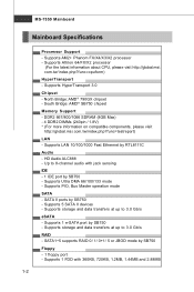
... Mainboard Specifications Processor Support - Supports Athlon 64/FX/X2 processor (For the latest information about CPU, please visit http://global.msi. Up to 8-channel audio with 360KB, 720KB, 1.2MB, 1.44MB and 2.88MB 1-2 Supports PIO, Bus Master operation mode SATA - Supports AM2+ Phenom FX/X4/X3/X2 processor - Supports HyperTransport 3.0 Chipset - Supports 5 SATA II devices - Supports storage and data transfers at up to 3.0 Gb/s RAID - SATA1~5 supports RAID 0/ 1/ 0+1/ 5 or JBOD mode by SB750 Floppy - 1 floppy port - Supports 1 FDD with jack sensing IDE - 1 IDE port...
... Mainboard Specifications Processor Support - Supports Athlon 64/FX/X2 processor (For the latest information about CPU, please visit http://global.msi. Up to 8-channel audio with 360KB, 720KB, 1.2MB, 1.44MB and 2.88MB 1-2 Supports PIO, Bus Master operation mode SATA - Supports AM2+ Phenom FX/X4/X3/X2 processor - Supports HyperTransport 3.0 Chipset - Supports 5 SATA II devices - Supports storage and data transfers at up to 3.0 Gb/s RAID - SATA1~5 supports RAID 0/ 1/ 0+1/ 5 or JBOD mode by SB750 Floppy - 1 floppy port - Supports 1 FDD with jack sensing IDE - 1 IDE port...

User Guide
Page 22
... +5V 24 GND pin 13 pin 12 ATX 12V Power Connector: JPWR2 This 12V power connector JPW 1 is highly recommended for system stability. 2-8 Then push down the power supply firmly into the connector. If you'd like . Power supply of the mainboard. 2. Maker sure that all the connectors are aligned. MS-7550 Mainboard Power Supply ATX 24-Pin Power Connector: JPWR1 This connector allows you like to use the 20-pin ATX power supply as you to connect an ATX 24-pin power supply.
... +5V 24 GND pin 13 pin 12 ATX 12V Power Connector: JPWR2 This 12V power connector JPW 1 is highly recommended for system stability. 2-8 Then push down the power supply firmly into the connector. If you'd like . Power supply of the mainboard. 2. Maker sure that all the connectors are aligned. MS-7550 Mainboard Power Supply ATX 24-Pin Power Connector: JPWR1 This connector allows you like to use the 20-pin ATX power supply as you to connect an ATX 24-pin power supply.
User Guide
Page 23
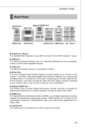
... high-definition video, plus multi-channel digital audio on a single cable. Back Panel Hardware Setup Keyboard/ Optical S/PDIF-Out Mouse VGA Port USB Ports LAN Line-In RS-Out HDMI Port Line-Out CS-Out USB Ports DVI-D Port eSATA Port USB Ports Mic SS-Out Keyboard / Mouse The standard PS/2® keyboard / mouse DIN connector is for attaching the eSATA external hard drive. 2-9 eSATA Port The eSATA port is for digital audio transmission to connect a LCD monitor. To connect an LCD monitor...
... high-definition video, plus multi-channel digital audio on a single cable. Back Panel Hardware Setup Keyboard/ Optical S/PDIF-Out Mouse VGA Port USB Ports LAN Line-In RS-Out HDMI Port Line-Out CS-Out USB Ports DVI-D Port eSATA Port USB Ports Mic SS-Out Keyboard / Mouse The standard PS/2® keyboard / mouse DIN connector is for attaching the eSATA external hard drive. 2-9 eSATA Port The eSATA port is for digital audio transmission to connect a LCD monitor. To connect an LCD monitor...
User Guide
Page 25
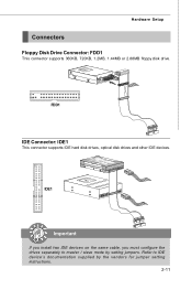
Hardware Setup Connectors Floppy Disk Drive Connector: FDD1 This connector supports 360KB, 720KB, 1.2MB, 1.44MB or 2.88MB floppy disk drive. Refer to master / slave mode by the vendors for jumper setting instructions. 2-11 IDE1 Important If you install two IDE devices on the same cable, you must configure the drives separately to IDE device's documentation supplied by setting jumpers. FDD1 IDE Connector: IDE1 This connector supports IDE hard disk drives, optical disk drives and other IDE devices.
Hardware Setup Connectors Floppy Disk Drive Connector: FDD1 This connector supports 360KB, 720KB, 1.2MB, 1.44MB or 2.88MB floppy disk drive. Refer to master / slave mode by the vendors for jumper setting instructions. 2-11 IDE1 Important If you install two IDE devices on the same cable, you must configure the drives separately to IDE device's documentation supplied by setting jumpers. FDD1 IDE Connector: IDE1 This connector supports IDE hard disk drives, optical disk drives and other IDE devices.

User Guide
Page 27
CPUFAN supports fan control. To clear the warning, you must enter the BIOS utility and clear the record. If the mainboard has a System Hardware Monitor chipset on the screen. the black wire is Ground and should be connected to the +12V; Please refer to the recommended CPU fans at processor's official website or consult the vendors for CPU_FAN1. You can install Dual Core Center utility that the red wire is opened, the chassis intrusion...
CPUFAN supports fan control. To clear the warning, you must enter the BIOS utility and clear the record. If the mainboard has a System Hardware Monitor chipset on the screen. the black wire is Ground and should be connected to the +12V; Please refer to the recommended CPU fans at processor's official website or consult the vendors for CPU_FAN1. You can install Dual Core Center utility that the red wire is opened, the chassis intrusion...

User Guide
Page 34
... speed (PCI_E1 & PCI_E4) White PCI Express x 1 Slot supports PCI Express x1 speed (PCI_E2 & PCI_E3) Important When adding or removing expansion cards, make sure that you unplug the power supply first. PCI Express x16 Slots support up to configure any necessary hardware or software settings for the expansion card to 250 MB/s transfer rate. The PCI Express x1 supports up to 4.0 GB/s transfer rate. Meanwhile, read the documentation for the expansion card, such as jumpers, switches or BIOS configuration...
... speed (PCI_E1 & PCI_E4) White PCI Express x 1 Slot supports PCI Express x1 speed (PCI_E2 & PCI_E3) Important When adding or removing expansion cards, make sure that you unplug the power supply first. PCI Express x16 Slots support up to configure any necessary hardware or software settings for the expansion card to 250 MB/s transfer rate. The PCI Express x1 supports up to 4.0 GB/s transfer rate. Meanwhile, read the documentation for the expansion card, such as jumpers, switches or BIOS configuration...

User Guide
Page 35
... typically connected to configure any necessary hardware or software settings for the expansion card to the PCI bus pins as jumpers, switches or BIOS configuration. Hardware Setup PCI (Peripheral Component Interconnect) Slot The PCI slot supports LAN card, SCSI card, USB card, and other add-on cards that comply with PCI specifications. 32-bit PCI Slot Important When adding or removing expansion cards, make sure that you unplug the power supply first. Meanwhile, read the documentation for the expansion card, such as follows: PCI Slot 1 PCI Slot 2 Order...
... typically connected to configure any necessary hardware or software settings for the expansion card to the PCI bus pins as jumpers, switches or BIOS configuration. Hardware Setup PCI (Peripheral Component Interconnect) Slot The PCI slot supports LAN card, SCSI card, USB card, and other add-on cards that comply with PCI specifications. 32-bit PCI Slot Important When adding or removing expansion cards, make sure that you unplug the power supply first. Meanwhile, read the documentation for the expansion card, such as follows: PCI Slot 1 PCI Slot 2 Order...
User Guide
Page 36
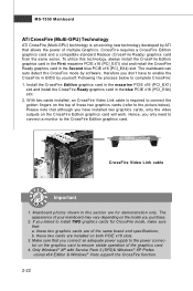
... Edition & Windows® Vista support the CrossFire function. 2-22 The mainboard can auto detect the CrossFire mode by software, therefore you don't have installed two graphics cards, only the video outputs on the CrossFire Edition graphics card will work. Install the CrossFire Edition graphics card in the mazarine PCIE x16 (PCI_EX1) slot and install the CrossFire Ready graphics card in BIOS by ATI that you connect an adequate power supply to the power connector on the graphics card to...
... Edition & Windows® Vista support the CrossFire function. 2-22 The mainboard can auto detect the CrossFire mode by software, therefore you don't have installed two graphics cards, only the video outputs on the CrossFire Edition graphics card will work. Install the CrossFire Edition graphics card in the mazarine PCIE x16 (PCI_EX1) slot and install the CrossFire Ready graphics card in BIOS by ATI that you connect an adequate power supply to the power connector on the graphics card to...

User Guide
Page 44
... the mainboard. Important IDE Primary Master/ Slave, SATA 1/2/3/4/5 Channel & E-SATA1 are appearing when you connect the HD devices to activate the S.M.A.R.T. (Self-Monitoring Analysis & Reporting Technology) capability for the hard disks. Floppy Drive A This item allows you to predict hard disk failure. DM A M ode Select DMA Mode. S.M.A.R.T is a utility that monitors your disk status to set the type of floppy drives installed. 3-7 Setting to the SATA connector. BIOS Setup Device / Vender / Size It will showing the device information that you connected to Auto enables LBA mode...
... the mainboard. Important IDE Primary Master/ Slave, SATA 1/2/3/4/5 Channel & E-SATA1 are appearing when you connect the HD devices to activate the S.M.A.R.T. (Self-Monitoring Analysis & Reporting Technology) capability for the hard disks. Floppy Drive A This item allows you to predict hard disk failure. DM A M ode Select DMA Mode. S.M.A.R.T is a utility that monitors your disk status to set the type of floppy drives installed. 3-7 Setting to the SATA connector. BIOS Setup Device / Vender / Size It will showing the device information that you connected to Auto enables LBA mode...

User Guide
Page 46
... enable or disable the APIC (Advanced Programmable Interrupt Controller). Due to compliance with PC2001 design guide, the system is powered on. MPS Table Version This field allows you to run in APIC mode. To find out which MPS (Multi-Processor Specification) version to select the MPS version supported by your operating system. 3-9 Settings are: [Enabled] Shows a still image (logo) on . Advanced BIOS Features BIOS Setup Full Screen LOGO Display...
... enable or disable the APIC (Advanced Programmable Interrupt Controller). Due to compliance with PC2001 design guide, the system is powered on. MPS Table Version This field allows you to run in APIC mode. To find out which MPS (Multi-Processor Specification) version to select the MPS version supported by your operating system. 3-9 Settings are: [Enabled] Shows a still image (logo) on . Advanced BIOS Features BIOS Setup Full Screen LOGO Display...

User Guide
Page 47
... to enter the sub-menu and the following screen appears: 3-10 MS-7550 Mainboard Primary Graphic's Adapter This setting specifies which graphic card is part of the chipset. CPU Feature Press to it via the various ACPI methods. VGA Share Memory The system shares memory to the onboard VGA. Boot Sequence Press to enter the sub-menu and the following screen appears: SVM Support This item is used to higher values, every PCI device can...
... to enter the sub-menu and the following screen appears: 3-10 MS-7550 Mainboard Primary Graphic's Adapter This setting specifies which graphic card is part of the chipset. CPU Feature Press to it via the various ACPI methods. VGA Share Memory The system shares memory to the onboard VGA. Boot Sequence Press to enter the sub-menu and the following screen appears: SVM Support This item is used to higher values, every PCI device can...

User Guide
Page 49
LAN Option ROM This item is used to enable/disable the onboard LAN controller. USB Device Legacy Support Select [Enabled] if you to enable/disable the onboard USB controller. Onboard LAN Controller This item is used to enable/disable the onboard audio controller. On-Chip ATA Devices Press to enter the sub-menu and the following screen appears: 3-12 Onboard Audio Controller This setting is used to decide whether to invoke the Boot ROM of the LAN controller. MS-7550 Mainboard Integrated Peripherals USB Controller This setting allows you need to use a USB-interfaced device in the...
LAN Option ROM This item is used to enable/disable the onboard LAN controller. USB Device Legacy Support Select [Enabled] if you to enable/disable the onboard USB controller. Onboard LAN Controller This item is used to enable/disable the onboard audio controller. On-Chip ATA Devices Press to enter the sub-menu and the following screen appears: 3-12 Onboard Audio Controller This setting is used to decide whether to invoke the Boot ROM of the LAN controller. MS-7550 Mainboard Integrated Peripherals USB Controller This setting allows you need to use a USB-interfaced device in the...

User Guide
Page 50
RAID Mode This item allows you to enable/ disable BIOS to used PCI busmastering for the first serial port. I/O Device Configuration Press to configure SATA mode. Set to the PS/2 connector of PS/2 device. 3-13 PS2 device select Select the PS/2 device which be pluged to [Auto], the system will auto detect the type of mainbaord. BIOS Setup PCI IDE BusMaster This item allows you to enter the sub-menu and the following screen appears: COM Port 1 Select an address and...
RAID Mode This item allows you to enable/ disable BIOS to used PCI busmastering for the first serial port. I/O Device Configuration Press to configure SATA mode. Set to the PS/2 connector of PS/2 device. 3-13 PS2 device select Select the PS/2 device which be pluged to [Auto], the system will auto detect the type of mainbaord. BIOS Setup PCI IDE BusMaster This item allows you to enter the sub-menu and the following screen appears: COM Port 1 Select an address and...

User Guide
Page 54
... opened. CPU Smart FAN Target The mainboard provides the Smart Fan function which can select a fan target value here. SYS FAN1 Control This item allows users to select how percentage of the monitored hardware devices/ components such as CPU voltage, temperatures and all of speed for cooling down automaticlly. H/W Monitor BIOS Setup Chassis Intrusion The field enables or disables the feature of the field will be activated. You can control the CPU fan speed automatically...
... opened. CPU Smart FAN Target The mainboard provides the Smart Fan function which can select a fan target value here. SYS FAN1 Control This item allows users to select how percentage of the monitored hardware devices/ components such as CPU voltage, temperatures and all of speed for cooling down automaticlly. H/W Monitor BIOS Setup Chassis Intrusion The field enables or disables the feature of the field will be activated. You can control the CPU fan speed automatically...
User Guide
Page 59
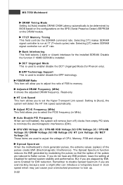
...] makes SDRAM signal controller run at 1T (T=clock cycles) rate. FSB/DRAM Ratio This item will allow you are overclocking because even a slight jitter can introduce a temporary boost in MHz). Spread Spectrum W hen the motherboard's clock generator pulses, the extreme values (spikes) of CPU, Memory, FSB and chipset. EPP Technology Support This is installed. Read-only. Auto Disable PCI Frequency W hen set to Enabled for Phenom only). The...
...] makes SDRAM signal controller run at 1T (T=clock cycles) rate. FSB/DRAM Ratio This item will allow you are overclocking because even a slight jitter can introduce a temporary boost in MHz). Spread Spectrum W hen the motherboard's clock generator pulses, the extreme values (spikes) of CPU, Memory, FSB and chipset. EPP Technology Support This is installed. Read-only. Auto Disable PCI Frequency W hen set to Enabled for Phenom only). The...

User Guide
Page 88
... clock and memory clock of this utility, we have to remind you install a graphics card of other brand, only hardware status of mainboard will show below . Dual Core Center Main Before using this utility. DOT Click DOT button to read current CPU temperature, FSB and CPU clock of the MSI mainboard would be available. B-3 E Click E button to enable or disable the Dynamic Overclocking Technology. If you : only when installing the MSI V044 (V044 has to install with the version...
... clock and memory clock of this utility, we have to remind you install a graphics card of other brand, only hardware status of mainboard will show below . Dual Core Center Main Before using this utility. DOT Click DOT button to read current CPU temperature, FSB and CPU clock of the MSI mainboard would be available. B-3 E Click E button to enable or disable the Dynamic Overclocking Technology. If you : only when installing the MSI V044 (V044 has to install with the version...
User Guide
Page 105
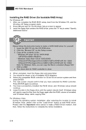
... SATA RAID: \\ATI\ATIDrv\SBDrv\RAID7xx * Windows Vista driver CD for SATA RAID: \\Chipset\ATI\Packages\Drivers\SBDrv\SB7xx\RAID\x86 (for 32bit) \\Chipset\ATI\Packages\Drivers\SBDrv\SB7xx\RAID\x64 (for 64bit) Note: for 32-bit/ 64-bit version system and then press ENTER. 7. Press ENTER again to install W indows Vista, please click on the Setup screen. 3. You have selected the RAID controller. Important Please follow the instructions to a medium (floppy/ CD/ DVD or USB...
... SATA RAID: \\ATI\ATIDrv\SBDrv\RAID7xx * Windows Vista driver CD for SATA RAID: \\Chipset\ATI\Packages\Drivers\SBDrv\SB7xx\RAID\x86 (for 32bit) \\Chipset\ATI\Packages\Drivers\SBDrv\SB7xx\RAID\x64 (for 64bit) Note: for 32-bit/ 64-bit version system and then press ENTER. 7. Press ENTER again to install W indows Vista, please click on the Setup screen. 3. You have selected the RAID controller. Important Please follow the instructions to a medium (floppy/ CD/ DVD or USB...
User Guide
Page 106
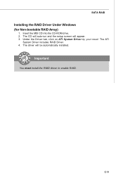
SATA RAID Installing the RAID Driver Under Windows (for Non-bootable RAID Array) 1. Under the Driver tab, click on ATI System Driver by your need. The driver will appear. 3. C-9 Insert the MSI CD into the CD-ROM drive. 2. The ATI System Driver includes RAID Driver. 4. The CD will auto-run and the setup screen will be automatically installed. Important You must install the RAID driver to enable RAID.
SATA RAID Installing the RAID Driver Under Windows (for Non-bootable RAID Array) 1. Under the Driver tab, click on ATI System Driver by your need. The driver will appear. 3. C-9 Insert the MSI CD into the CD-ROM drive. 2. The ATI System Driver includes RAID Driver. 4. The CD will auto-run and the setup screen will be automatically installed. Important You must install the RAID driver to enable RAID.


