LM21XP Manual
Page 1
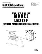
The Chamberlain Group, Inc. 845 Larch Avenue Elmhurst, Illinois 60126-1196 www.liftmaster.com OWNER'S MANUAL MODEL LM21XP EXTENDED PERFORMANCE RELEASE DEVICE
The Chamberlain Group, Inc. 845 Larch Avenue Elmhurst, Illinois 60126-1196 www.liftmaster.com OWNER'S MANUAL MODEL LM21XP EXTENDED PERFORMANCE RELEASE DEVICE
LM21XP Manual
Page 2
... all safety instructions. • DO NOT attempt repair or service of -the-art electronic control circuitry. Read the warnings carefully. INTRODUCTION GENERAL DESCRIPTION The LiftMaster® LM21XP Release Device is designated to be powered from 24Vdc received from an approved UL 1481 regulated power supply with the warnings that accompany it will alert...
... all safety instructions. • DO NOT attempt repair or service of -the-art electronic control circuitry. Read the warnings carefully. INTRODUCTION GENERAL DESCRIPTION The LiftMaster® LM21XP Release Device is designated to be powered from 24Vdc received from an approved UL 1481 regulated power supply with the warnings that accompany it will alert...
LM21XP Manual
Page 3
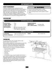
... possible SERIOUS INJURY or DEATH: CAUTION • DO NOT use of electrical power to the door manufacturer's recommendations for the release device. SPECIFICATIONS ELECTRICAL SPECIFICATIONS VOLTAGE RATING: STANDBY CURRENT: ALARM CURRENT: INITIATING DEVICE: 24Vdc .100A .15A Maximum line impedance 20...and/or other applicable building and fire standards, guidelines, regulations and codes including, but not limited to assure proper operation of release device. When using 4-wire smoke detectors with the installation of -line relay. CONTACT RATING) 1A 24Vdc Resistive LOAD RATING: PHYSICAL...
... possible SERIOUS INJURY or DEATH: CAUTION • DO NOT use of electrical power to the door manufacturer's recommendations for the release device. SPECIFICATIONS ELECTRICAL SPECIFICATIONS VOLTAGE RATING: STANDBY CURRENT: ALARM CURRENT: INITIATING DEVICE: 24Vdc .100A .15A Maximum line impedance 20...and/or other applicable building and fire standards, guidelines, regulations and codes including, but not limited to assure proper operation of release device. When using 4-wire smoke detectors with the installation of -line relay. CONTACT RATING) 1A 24Vdc Resistive LOAD RATING: PHYSICAL...
LM21XP Manual
Page 4
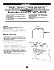
...) according to adequately redirect sash chain pull. 4. Install end link by Underwriters Laboratories. Smoke Detector Eyebolt Fuse Links Turnbuckle Releasing Unit Chain End Link Chain Fire Door 4 WARNING I N S TA L L AT I O N IMPORTANT INSTALLATION INSTRUCTIONS... WARNING To reduce the risk of 40 lbs. Concrete anchors MUST be perpendicular to do so. 3. Mount the release device on releasing device. Install an eyebolt a minimum distance of NFPA 72 - READ AND FOLLOW ALL INSTALLATION WARNINGS AND INSTRUCTIONS. 2. Installation Requirements...
...) according to adequately redirect sash chain pull. 4. Install end link by Underwriters Laboratories. Smoke Detector Eyebolt Fuse Links Turnbuckle Releasing Unit Chain End Link Chain Fire Door 4 WARNING I N S TA L L AT I O N IMPORTANT INSTALLATION INSTRUCTIONS... WARNING To reduce the risk of 40 lbs. Concrete anchors MUST be perpendicular to do so. 3. Mount the release device on releasing device. Install an eyebolt a minimum distance of NFPA 72 - READ AND FOLLOW ALL INSTALLATION WARNINGS AND INSTRUCTIONS. 2. Installation Requirements...
LM21XP Manual
Page 5
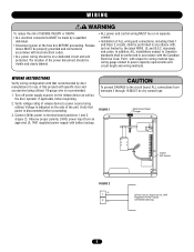
...beginning. 2. The location of the power disconnect should be on the side of the unit. standards and codes. Verify voltage rating of release device to power source being utilized. 18-gauge wire is indicated on a dedicated circuit and well protected. Verify that recommended by a.... • Disconnect power at the fuse box BEFORE proceeding. In addition, ALL installations subject to , the latest NFPA, UL and N.E.C. Release device MUST be properly grounded and connected in accordance with local electrical codes. • ALL power wiring should be visible and clearly labeled....
...beginning. 2. The location of the power disconnect should be on the side of the unit. standards and codes. Verify voltage rating of release device to power source being utilized. 18-gauge wire is indicated on a dedicated circuit and well protected. Verify that recommended by a.... • Disconnect power at the fuse box BEFORE proceeding. In addition, ALL installations subject to , the latest NFPA, UL and N.E.C. Release device MUST be properly grounded and connected in accordance with local electrical codes. • ALL power wiring should be visible and clearly labeled....
LM21XP Manual
Page 7
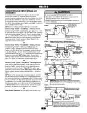
...installed as an approved UL 1481 regulated power supply providing battery backup support. (-) Power from N/O initiating device loop to the release device's terminal board. NOTE: Make certain that the factory-installed jumper between devices may be installed with other alarm equipment. ...FIGURE 3 10k Ohm @1/2 watt Supervisory Resistor (LMEOLRES-10) - IN/OUT + OUT + IN COM NO - Power from a source other than the release device, such as shown in place. This option is a supervised, current-limited circuit. Observe proper polarity, 3 (+), 4 (-) when attaching to positions...
...installed as an approved UL 1481 regulated power supply providing battery backup support. (-) Power from N/O initiating device loop to the release device's terminal board. NOTE: Make certain that the factory-installed jumper between devices may be installed with other alarm equipment. ...FIGURE 3 10k Ohm @1/2 watt Supervisory Resistor (LMEOLRES-10) - IN/OUT + OUT + IN COM NO - Power from a source other than the release device, such as shown in place. This option is a supervised, current-limited circuit. Observe proper polarity, 3 (+), 4 (-) when attaching to positions...
LM21XP Manual
Page 8
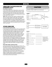
...Proximity Switch Part No. WIRING WARNING CONNECTIONS OF INITIATING DEVICES AND ACCESSORIES (cont'd) Relay Module Installation In lieu of smoke detectors, the release device may damage the device's terminals and/or circuit board. NOTE: When choosing a relay module to N/O Position on alarm, ...thereby eliminating nuisance gravity drops through such a relay module into the release device will be dry contact type. Black + Fire Alarm Control Panel OPTIONAL CONNECTIONS CLOSE DOOR DETECTION OPTION Connect wiring from the Alarm...
...Proximity Switch Part No. WIRING WARNING CONNECTIONS OF INITIATING DEVICES AND ACCESSORIES (cont'd) Relay Module Installation In lieu of smoke detectors, the release device may damage the device's terminals and/or circuit board. NOTE: When choosing a relay module to N/O Position on alarm, ...thereby eliminating nuisance gravity drops through such a relay module into the release device will be dry contact type. Black + Fire Alarm Control Panel OPTIONAL CONNECTIONS CLOSE DOOR DETECTION OPTION Connect wiring from the Alarm...
LM21XP Manual
Page 9
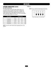
WIRING OPTIONAL CONNECTIONS (cont'd) DIP SWITCH SELECTION The release device will provide a factory default delay of 10 seconds shown. ON 1 2 3 4 Factory default setting of ... 3 is unused and should remain in the OFF position. A 4-position DIP Switch found on the PC board within the release device can be used to minimize nuisance alarms) before applying power to one of four preset delays. The optional delay settings ... adjust the length of the delay to the system. 9 NOTE: Set all DIP switch options before releasing the fusible link chain upon alarm or power loss.
WIRING OPTIONAL CONNECTIONS (cont'd) DIP SWITCH SELECTION The release device will provide a factory default delay of 10 seconds shown. ON 1 2 3 4 Factory default setting of ... 3 is unused and should remain in the OFF position. A 4-position DIP Switch found on the PC board within the release device can be used to minimize nuisance alarms) before applying power to one of four preset delays. The optional delay settings ... adjust the length of the delay to the system. 9 NOTE: Set all DIP switch options before releasing the fusible link chain upon alarm or power loss.
LM21XP Manual
Page 10
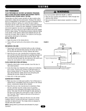
...OPENING WHILE TESTING! Verify options ordered and installed with power applied. Depress and continue to hold test button on the device and release the reset button in order to unit. TESTING TEST PROCEDURES TO BE PERFORMED BY FACTORY AUTHORIZED PERSONNEL ONLY! All tests may not... position. Verify that Close Door Detection LED (yellow) is in no way be performed and witnessed for normal operation is independent of release device. Reset the door per door manufacturer's instructions. Turn off all options. Using the chain hoist or motor operator, lower the ...
...OPENING WHILE TESTING! Verify options ordered and installed with power applied. Depress and continue to hold test button on the device and release the reset button in order to unit. TESTING TEST PROCEDURES TO BE PERFORMED BY FACTORY AUTHORIZED PERSONNEL ONLY! All tests may not... position. Verify that Close Door Detection LED (yellow) is in no way be performed and witnessed for normal operation is independent of release device. Reset the door per door manufacturer's instructions. Turn off all options. Using the chain hoist or motor operator, lower the ...
LM21XP Manual
Page 11
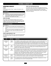
... the proximity switch. TROUBLESHOOTING OPERATIONAL CHECKLIST POWER Is the red LED, labeled "Power," located on . Check voltage; Conversely, the release device will not release the fusible link assembly in the closed and activating the proximity switch. Yes Move on the bottom of an alarm panel. CIRCUIT BOARD...loop is in alarm, cycle power off and then on the circuit board located behind the terminal board. If not, the release device will always release the fusible link assembly when powered or reset. There should be picked up from an approved UL 1481 regulated power supply....
... the proximity switch. TROUBLESHOOTING OPERATIONAL CHECKLIST POWER Is the red LED, labeled "Power," located on . Check voltage; Conversely, the release device will not release the fusible link assembly in the closed and activating the proximity switch. Yes Move on the bottom of an alarm panel. CIRCUIT BOARD...loop is in alarm, cycle power off and then on the circuit board located behind the terminal board. If not, the release device will always release the fusible link assembly when powered or reset. There should be picked up from an approved UL 1481 regulated power supply....
LM21XP Manual
Page 12
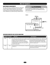
... unit has been designed and tested for use in a constant closed position. FIGURE 1 Mechanical Reset Plunger Front of Release Device End Link Bottom of the unit at least once every 90 days is connected as described in the installation manual...BEFORE performing ANY maintenance. that the switch is applied, check switched "on the release device. Testing of Release Device Electronic Reset Button Test Button Red LED (Line Power Present) Yellow LED (Close Door Detection Release Disabled) ENCLOSURE MOUNTED LEDS STATUS INDICATORS LED Label LED Color Description Action Required ...
... unit has been designed and tested for use in a constant closed position. FIGURE 1 Mechanical Reset Plunger Front of Release Device End Link Bottom of the unit at least once every 90 days is connected as described in the installation manual...BEFORE performing ANY maintenance. that the switch is applied, check switched "on the release device. Testing of Release Device Electronic Reset Button Test Button Red LED (Line Power Present) Yellow LED (Close Door Detection Release Disabled) ENCLOSURE MOUNTED LEDS STATUS INDICATORS LED Label LED Color Description Action Required ...


