LM21XP Manual
Page 1
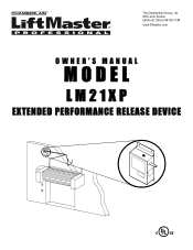
The Chamberlain Group, Inc. 845 Larch Avenue Elmhurst, Illinois 60126-1196 www.liftmaster.com OWNER'S MANUAL MODEL LM21XP EXTENDED PERFORMANCE RELEASE DEVICE
The Chamberlain Group, Inc. 845 Larch Avenue Elmhurst, Illinois 60126-1196 www.liftmaster.com OWNER'S MANUAL MODEL LM21XP EXTENDED PERFORMANCE RELEASE DEVICE
LM21XP Manual
Page 2
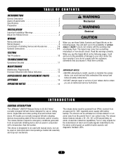
... Release Device 4 WIRING Wiring Instructions 5 Wiring Diagram 6 Connections of Initiating Devices and Accessories 7-8 Optional Connections 8-9 TESTING Test Procedures 10 TROUBLESHOOTING Operational Checklist 11 MAINTENANCE Maintenance Requirements 12 Enclosure Mounted LEDs Status Indicators 12 ACCESSORIES AND REPLACEMENT PARTS 13 APPENDIX 14 OPERATOR NOTES 15 WARNING Mechanical CAUTION WARNING WAEleRctrNicaINl G WARNING CAUTION When you see this manual and follow all safety instructions. • DO NOT attempt repair or service of your door and/or the door operator...
... Release Device 4 WIRING Wiring Instructions 5 Wiring Diagram 6 Connections of Initiating Devices and Accessories 7-8 Optional Connections 8-9 TESTING Test Procedures 10 TROUBLESHOOTING Operational Checklist 11 MAINTENANCE Maintenance Requirements 12 Enclosure Mounted LEDs Status Indicators 12 ACCESSORIES AND REPLACEMENT PARTS 13 APPENDIX 14 OPERATOR NOTES 15 WARNING Mechanical CAUTION WARNING WAEleRctrNicaINl G WARNING CAUTION When you see this manual and follow all safety instructions. • DO NOT attempt repair or service of your door and/or the door operator...
LM21XP Manual
Page 3
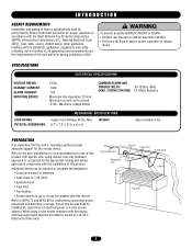
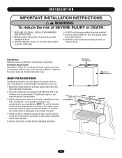
... shall be installed for supervision of electrical power to exceed .010A.; Smoke Detector Eyebolt Fuse Links Turnbuckle Releasing Unit Chain End Link Chain Fire Door 3 PREPARATION It is imperative that the wall or mounting surface provide adequate support for the release device. Use only hardware approved or recognized by means of a UL/ULC listed end-of release device. Refer to the door manufacturer's recommendations for use this device without fuse links installed. • Test...
... shall be installed for supervision of electrical power to exceed .010A.; Smoke Detector Eyebolt Fuse Links Turnbuckle Releasing Unit Chain End Link Chain Fire Door 3 PREPARATION It is imperative that the wall or mounting surface provide adequate support for the release device. Use only hardware approved or recognized by means of a UL/ULC listed end-of release device. Refer to the door manufacturer's recommendations for use this device without fuse links installed. • Test...
LM21XP Manual
Page 4
...-hook, fuse links, turnbuckles-not provided) according to door types. all wiring must be used if mounting release device into masonry. 6. Install an eyebolt a minimum distance of pull must be performed in and release mechanical reset to adequately redirect sash chain pull. 4. Smoke Detector Eyebolt Fuse Links Turnbuckle Releasing Unit Chain End Link Chain Fire Door 4 READ AND FOLLOW ALL INSTALLATION WARNINGS AND INSTRUCTIONS. 2. Installation Requirements: Intended for "Indoor Dry" locations; Secure the release device enclosure...
...-hook, fuse links, turnbuckles-not provided) according to door types. all wiring must be used if mounting release device into masonry. 6. Install an eyebolt a minimum distance of pull must be performed in and release mechanical reset to adequately redirect sash chain pull. 4. Smoke Detector Eyebolt Fuse Links Turnbuckle Releasing Unit Chain End Link Chain Fire Door 4 READ AND FOLLOW ALL INSTALLATION WARNINGS AND INSTRUCTIONS. 2. Installation Requirements: Intended for "Indoor Dry" locations; Secure the release device enclosure...
LM21XP Manual
Page 5
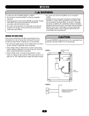
... fuse box BEFORE proceeding. standards and codes. FIGURE 1 Mechanical Reset Plunger Option DIP Switch FIGURE 2 + 1 2- 24Vdc from an approved UL 1481 regulated power supply with specific door and accessories being utilized. The location of the power disconnect should be dry contact type. Turn off power supply sources for use of ALL wiring and connections, including Class 1 and Class 2 circuits, shall be performed in separate conduit. • Installation...
... fuse box BEFORE proceeding. standards and codes. FIGURE 1 Mechanical Reset Plunger Option DIP Switch FIGURE 2 + 1 2- 24Vdc from an approved UL 1481 regulated power supply with specific door and accessories being utilized. The location of the power disconnect should be dry contact type. Turn off power supply sources for use of ALL wiring and connections, including Class 1 and Class 2 circuits, shall be performed in separate conduit. • Installation...
LM21XP Manual
Page 6
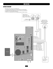
... NO Trouble NC Trouble Com Trouble NO K3 K1 (YE) (GY) P1 + SW2 SW3 POWER ON LED 1 DISABLE LED 3 N.O. Supervised, power limited circuit, 20 Ohm maximum line impedance. 2. In/Out Normally Closed Initiation Loop (1) (3) Keep jumper between 5 & 6 if unused. Close Door Proximity Switch (2) 6 Maximum of 22-18 AWG wiring. 1. Power from an approved UL1481 regulated supply with battery backup. 2-Wire Detector Initiation Loop (1) (3) Keep 10k Ohm resister between 3 & 4 if unused. WIRING WIRING DIAGRAM Field Wiring...
... NO Trouble NC Trouble Com Trouble NO K3 K1 (YE) (GY) P1 + SW2 SW3 POWER ON LED 1 DISABLE LED 3 N.O. Supervised, power limited circuit, 20 Ohm maximum line impedance. 2. In/Out Normally Closed Initiation Loop (1) (3) Keep jumper between 5 & 6 if unused. Close Door Proximity Switch (2) 6 Maximum of 22-18 AWG wiring. 1. Power from an approved UL1481 regulated supply with battery backup. 2-Wire Detector Initiation Loop (1) (3) Keep 10k Ohm resister between 3 & 4 if unused. WIRING WIRING DIAGRAM Field Wiring...
LM21XP Manual
Page 7
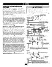
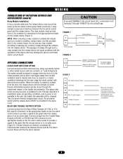
... loop to the release control circuit and void warranty. Incorrect wiring between terminal positions 5 and 6, connect wiring from a source other alarm equipment. OR Relay Module Installation as an approved UL 1481 regulated power supply providing battery backup support. This option is a supervised, current-limited circuit. OR Normally Closed "4-Wire," Class B Style A Initiating Devices After removing the factory-installed jumper between devices may be installed for supervision of electrical power to 4-wire smoke detector. Power from Control Panel...
... loop to the release control circuit and void warranty. Incorrect wiring between terminal positions 5 and 6, connect wiring from a source other alarm equipment. OR Relay Module Installation as an approved UL 1481 regulated power supply providing battery backup support. This option is a supervised, current-limited circuit. OR Normally Closed "4-Wire," Class B Style A Initiating Devices After removing the factory-installed jumper between devices may be installed for supervision of electrical power to 4-wire smoke detector. Power from Control Panel...
LM21XP Manual
Page 8
... fire alarm control panel and the release device. RELAY AND TROUBLE OUTPUTS OPTION Connect wiring from the Trouble Relay Outputs (#14 N/C or #16 N/O and #15 Common) to the appropriate inputs on the fire alarm control panel to N/O Position on the release device (Figure 7). CAUTION To prevent DAMAGE to the circuit board, ALL connections from N/O electrical loop, using a proximity switch or other similar device with the fire alarm installer. 7 Attach to...
... fire alarm control panel and the release device. RELAY AND TROUBLE OUTPUTS OPTION Connect wiring from the Trouble Relay Outputs (#14 N/C or #16 N/O and #15 Common) to the appropriate inputs on the fire alarm control panel to N/O Position on the release device (Figure 7). CAUTION To prevent DAMAGE to the circuit board, ALL connections from N/O electrical loop, using a proximity switch or other similar device with the fire alarm installer. 7 Attach to...
LM21XP Manual
Page 9
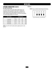
.... NOTE: Set all DIP switch options before releasing the fusible link chain upon alarm or power loss. WIRING OPTIONAL CONNECTIONS (cont'd) DIP SWITCH SELECTION The release device will provide a factory default delay of 10 seconds (to one of the two available voice messages. ON 1 2 3 4 Factory default setting of four ... FIGURE 10 NOTE: Position 4 is used to adjust the length of the delay to minimize nuisance alarms) before applying power to select one of 10 seconds shown. A 4-position DIP Switch found on the PC board within the release device can be used to the system. 9
.... NOTE: Set all DIP switch options before releasing the fusible link chain upon alarm or power loss. WIRING OPTIONAL CONNECTIONS (cont'd) DIP SWITCH SELECTION The release device will provide a factory default delay of 10 seconds (to one of the two available voice messages. ON 1 2 3 4 Factory default setting of four ... FIGURE 10 NOTE: Position 4 is used to adjust the length of the delay to minimize nuisance alarms) before applying power to select one of 10 seconds shown. A 4-position DIP Switch found on the PC board within the release device can be used to the system. 9
LM21XP Manual
Page 10
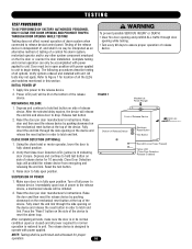
... power applied to unit to unit. Raise the door and then reset the release device by pushing downward on the fire door or counter fire door installation. Testing does not affect normal operation of release device for proper operation. 10 Apply line power to drop. Reset the door per door manufacturer's instructions. Depress and continue to hold test button on the bottom of power to operate with unit. Red LED (Line Power Present) Yellow LED (Close Door Detection Release...
... power applied to unit to unit. Raise the door and then reset the release device by pushing downward on the fire door or counter fire door installation. Testing does not affect normal operation of release device for proper operation. 10 Apply line power to drop. Reset the door per door manufacturer's instructions. Depress and continue to hold test button on the bottom of power to operate with unit. Red LED (Line Power Present) Yellow LED (Close Door Detection Release...
LM21XP Manual
Page 11
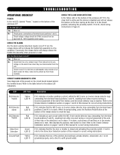
..., and the smoke detector loop is in alarm. Conversely, the release device will not release the fusible link assembly in Figure 8. If not lit, refer to the Close Door Detection section of the release device to reset. Is the Red LED Lit? When lit during testing, press the Auxiliary Reset Button at terminal board positions 1 and 2. At times, noise can be 24Vdc received from the unit. Refer to...
..., and the smoke detector loop is in alarm. Conversely, the release device will not release the fusible link assembly in Figure 8. If not lit, refer to the Close Door Detection section of the release device to reset. Is the Red LED Lit? When lit during testing, press the Auxiliary Reset Button at terminal board positions 1 and 2. At times, noise can be 24Vdc received from the unit. Refer to...
LM21XP Manual
Page 12
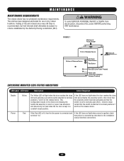
... power BEFORE performing ANY maintenance. If the LED does not light when the door reaches the close limit and activates a proximity switch attached to normally open (N.O.). FIGURE 1 Mechanical Reset Plunger Front of Release Device End Link Bottom of the unit at least once every 90 days is kept in dry, indoor locations. WARNING MAINTENANCE WARNING CAUTION MAINTENANCE REQUIREMENTS The release device has no scheduled maintenance requirements. Power Red If the Red LED...
... power BEFORE performing ANY maintenance. If the LED does not light when the door reaches the close limit and activates a proximity switch attached to normally open (N.O.). FIGURE 1 Mechanical Reset Plunger Front of Release Device End Link Bottom of the unit at least once every 90 days is kept in dry, indoor locations. WARNING MAINTENANCE WARNING CAUTION MAINTENANCE REQUIREMENTS The release device has no scheduled maintenance requirements. Power Red If the Red LED...
LM21XP Manual
Page 13
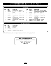
... 12 13 PART # DESCRIPTION LM4WT-B Smoke Detector - 12/24Vdc 4-Wire Photo with Thermal and Form C Relay LM1424 Smoke Detector - 24Vdc Ion LM1412 Smoke Detector - 12Vdc Ion LMTH135 Heat Detector - 135 Degree Fixed Temperature LMTH194 Heat Detector - 194 Degree Fixed Temperature LMEOLR1224 End-of-Line Relay - 12/24Vdc LMEOLR120 End-of-Line Relay - 120Vac REPLACEMENT PARTS ITEM 1 2 3 4 PART # DESCRIPTION LMRK Reset Knob LMELH End Link 01-32046 Owner's Manual LMEOLRES-10...
... 12 13 PART # DESCRIPTION LM4WT-B Smoke Detector - 12/24Vdc 4-Wire Photo with Thermal and Form C Relay LM1424 Smoke Detector - 24Vdc Ion LM1412 Smoke Detector - 12Vdc Ion LMTH135 Heat Detector - 135 Degree Fixed Temperature LMTH194 Heat Detector - 194 Degree Fixed Temperature LMEOLR1224 End-of-Line Relay - 12/24Vdc LMEOLR120 End-of-Line Relay - 120Vac REPLACEMENT PARTS ITEM 1 2 3 4 PART # DESCRIPTION LMRK Reset Knob LMELH End Link 01-32046 Owner's Manual LMEOLRES-10...
LM21XP Manual
Page 14
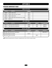
... above will require a separate power source. Refer to product manual. 14 DESCRIPTION LM2W-B LM2WT-B LM4W-B LM4WT-B LM1424 24Vdc 2-Wire Photo 24Vdc 2-Wire Photo with Thermal 24Vdc 4-Wire Photo 24Vdc 4-Wire Photo with Thermal & Form C Relay 24Vdc Ion SYSTEM SENSOR MODEL NO. 2W-B 2WT-B 4W-B 4WT-B #1424 HEAT DETECTORS MODEL NO. PAM-1 LIFTMASTER NO. DESCRIPTION LMTH135 135 Degree Fixed Temperature LMTH194 194 Degree Fixed Temperature SYSTEM SENSOR MODEL NO. #5603 #5604...
... above will require a separate power source. Refer to product manual. 14 DESCRIPTION LM2W-B LM2WT-B LM4W-B LM4WT-B LM1424 24Vdc 2-Wire Photo 24Vdc 2-Wire Photo with Thermal 24Vdc 4-Wire Photo 24Vdc 4-Wire Photo with Thermal & Form C Relay 24Vdc Ion SYSTEM SENSOR MODEL NO. 2W-B 2WT-B 4W-B 4WT-B #1424 HEAT DETECTORS MODEL NO. PAM-1 LIFTMASTER NO. DESCRIPTION LMTH135 135 Degree Fixed Temperature LMTH194 194 Degree Fixed Temperature SYSTEM SENSOR MODEL NO. #5603 #5604...

LM21XP Manual
Page 16
All Rights Reserved 01-32046B Issue Date 7/27/2006 © 2006, The Chamberlain Group, Inc.
All Rights Reserved 01-32046B Issue Date 7/27/2006 © 2006, The Chamberlain Group, Inc.


