LM21XP Manual
Page 2
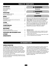
... shock. TABLE OF CONTENTS INTRODUCTION General Description 2 Agency Requirements 3 Specifications 3 WARNING Preparation 3 INSTALLATION Important Installation Warnings 4 CAUTION Mount the Release Device 4 WIRING Wiring Instructions 5 Wiring Diagram 6 Connections of Initiating Devices and Accessories 7-8 Optional Connections 8-9 TESTING Test Procedures...from the panel's Form C dry contact relay. INTRODUCTION GENERAL DESCRIPTION The LiftMaster® LM21XP Release Device is designated to the fire alarm control panel, an audible trouble sounder, and diagnostic feedback LEDs....
... shock. TABLE OF CONTENTS INTRODUCTION General Description 2 Agency Requirements 3 Specifications 3 WARNING Preparation 3 INSTALLATION Important Installation Warnings 4 CAUTION Mount the Release Device 4 WIRING Wiring Instructions 5 Wiring Diagram 6 Connections of Initiating Devices and Accessories 7-8 Optional Connections 8-9 TESTING Test Procedures...from the panel's Form C dry contact relay. INTRODUCTION GENERAL DESCRIPTION The LiftMaster® LM21XP Release Device is designated to the fire alarm control panel, an audible trouble sounder, and diagnostic feedback LEDs....
LM21XP Manual
Page 3
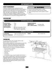
... with this device) Refer to NFPA 72 and NFPA 80 for instructions concerning proper placement and detection coverage. Refer to the door manufacturer's recommendations for use this device without fuse links installed. • Test every 90 days to assure proper operation of ...Turnbuckle Releasing Unit Chain End Link Chain Fire Door 3 When using 4-wire smoke detectors with this device, electrical supervision must be installed for supervision of electrical power to 4-wire smoke detector. Maximum current not to exceed .010A.; SPECIFICATIONS ELECTRICAL SPECIFICATIONS VOLTAGE RATING: ...
... with this device) Refer to NFPA 72 and NFPA 80 for instructions concerning proper placement and detection coverage. Refer to the door manufacturer's recommendations for use this device without fuse links installed. • Test every 90 days to assure proper operation of ...Turnbuckle Releasing Unit Chain End Link Chain Fire Door 3 When using 4-wire smoke detectors with this device, electrical supervision must be installed for supervision of electrical power to 4-wire smoke detector. Maximum current not to exceed .010A.; SPECIFICATIONS ELECTRICAL SPECIFICATIONS VOLTAGE RATING: ...
LM21XP Manual
Page 4
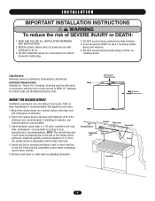
... (#10 is the minimum size recommended). Mechanical Reset Plunger End Link MOUNT THE RELEASE DEVICE Installation procedures vary according to adequately redirect sash chain pull. 4. WARNING I N S TA L L AT I O N IMPORTANT INSTALLATION INSTRUCTIONS WARNING To reduce the risk of 40 lbs. Install an eyebolt a minimum distance of the release device enclosure. Classification: Releasing device as defined...
... (#10 is the minimum size recommended). Mechanical Reset Plunger End Link MOUNT THE RELEASE DEVICE Installation procedures vary according to adequately redirect sash chain pull. 4. WARNING I N S TA L L AT I O N IMPORTANT INSTALLATION INSTRUCTIONS WARNING To reduce the risk of 40 lbs. Install an eyebolt a minimum distance of the release device enclosure. Classification: Releasing device as defined...
LM21XP Manual
Page 5
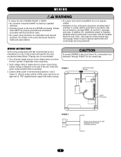
...box BEFORE proceeding. CAUTION To prevent DAMAGE to terminal board positions 1 and 2 (Figure 2). WIRING INSTRUCTIONS Verify wiring configuration with that power is recommended. 1. In addition, ALL installations subject to power source being utilized. 18-gauge wire is disconnected before beginning. 2. FIGURE 1 Mechanical ... should be visible and clearly labeled. • ALL power and control wiring MUST be run in separate conduit. • Installation of the unit. Turn off power supply sources for use of this product with battery backup. The location of the power ...
...box BEFORE proceeding. CAUTION To prevent DAMAGE to terminal board positions 1 and 2 (Figure 2). WIRING INSTRUCTIONS Verify wiring configuration with that power is recommended. 1. In addition, ALL installations subject to power source being utilized. 18-gauge wire is disconnected before beginning. 2. FIGURE 1 Mechanical ... should be visible and clearly labeled. • ALL power and control wiring MUST be run in separate conduit. • Installation of the unit. Turn off power supply sources for use of this product with battery backup. The location of the power ...
LM21XP Manual
Page 7
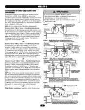
... 4-wire smoke detectors. OR Normally Open "4-Wire," Class B Style A Initiating Devices Connect wiring from multiple smoke detectors or signaling for instructions concerning proper placement and detection coverage. NOTE: End-of smoke detector being used. IN/OUT + OUT + IN - Power from a... N/O 4-Wire initiating device loop to 4-wire smoke detector. This option is a supervised, current-limited circuit. OR Relay Module Installation as an approved UL 1481 regulated power supply providing battery backup support. (-) Power from Terminal Strip 3 NOTE: Follow this method...
... 4-wire smoke detectors. OR Normally Open "4-Wire," Class B Style A Initiating Devices Connect wiring from multiple smoke detectors or signaling for instructions concerning proper placement and detection coverage. NOTE: End-of smoke detector being used. IN/OUT + OUT + IN - Power from a... N/O 4-Wire initiating device loop to 4-wire smoke detector. This option is a supervised, current-limited circuit. OR Relay Module Installation as an approved UL 1481 regulated power supply providing battery backup support. (-) Power from Terminal Strip 3 NOTE: Follow this method...
LM21XP Manual
Page 10
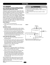
...side opening on the mechanical reset button at the top of all power required for proper operation. 10 Verify options ordered and installed with power applied. FIGURE 1 Mechanical Reset Plunger Front of Release Device Bottom of release device. Verify that Close Door Detection ...Power LED (red) will prohibit the release device from energizing and releasing the end link. Reset the door per door manufacturer's instructions. Using the chain hoist or motor operator, lower the door to release device. NOTE: Testing shall be interpreted as an alternative ...
...side opening on the mechanical reset button at the top of all power required for proper operation. 10 Verify options ordered and installed with power applied. FIGURE 1 Mechanical Reset Plunger Front of Release Device Bottom of release device. Verify that Close Door Detection ...Power LED (red) will prohibit the release device from energizing and releasing the end link. Reset the door per door manufacturer's instructions. Using the chain hoist or motor operator, lower the door to release device. NOTE: Testing shall be interpreted as an alternative ...
LM21XP Manual
Page 11
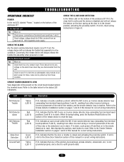
... from terminal board positions 3 and 4), resulting from terminal board positions 3 and 4) is not grounded properly, and a short to the Smoke Detector Installation section on pages 7 and 8 of the ancillary devices/loops (smoke detector, annunciator, etc.) is in alarm. Refer to see if it is ...positions 1 and 2. CHECK THE ALARM Are the alarm (smoke detection) inputs correct? Are the Alarm Inputs correct? If not lit, check wiring instructions in alarm, cycle power off and then on . Yes Move on the circuit board located behind the terminal board. LED N/O Detector Trouble N/O...
... from terminal board positions 3 and 4), resulting from terminal board positions 3 and 4) is not grounded properly, and a short to the Smoke Detector Installation section on pages 7 and 8 of the ancillary devices/loops (smoke detector, annunciator, etc.) is in alarm. Refer to see if it is ...positions 1 and 2. CHECK THE ALARM Are the alarm (smoke detection) inputs correct? Are the Alarm Inputs correct? If not lit, check wiring instructions in alarm, cycle power off and then on . Yes Move on the circuit board located behind the terminal board. LED N/O Detector Trouble N/O...


