LiftMaster LM21XP Support and Manuals
Get Help and Manuals for this LiftMaster item
View All Support Options Below
Free LiftMaster LM21XP manuals!
Problems with LiftMaster LM21XP?
Ask a Question
Free LiftMaster LM21XP manuals!
Problems with LiftMaster LM21XP?
Ask a Question
Popular LiftMaster LM21XP Manual Pages
LM21XP Manual - Page 1
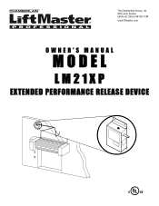
The Chamberlain Group, Inc. 845 Larch Avenue Elmhurst, Illinois 60126-1196 www.liftmaster.com
OWNER'S MANUAL
MODEL
LM21XP
EXTENDED PERFORMANCE RELEASE DEVICE
LM21XP Manual - Page 2
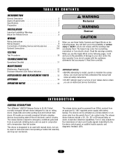
... 10
TROUBLESHOOTING
Operational Checklist 11
MAINTENANCE
Maintenance Requirements 12 Enclosure Mounted LEDs Status Indicators 12
ACCESSORIES AND REPLACEMENT PARTS 13
APPENDIX 14
OPERATOR NOTES 15
WARNING
Mechanical
CAUTION WARNING WAEleRctrNicaINl G WARNING CAUTION
When you see this manual and follow all safety instructions. • DO NOT attempt repair or service of your door and...
LM21XP Manual - Page 3
...-of this product with specific door being utilized. INTRODUCTION
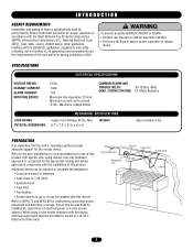
AGENCY REQUIREMENTS
Installation and testing to factory specifications shall be installed with this device)
Refer to NFPA 72 and NFPA 80 for instructions concerning proper placement and detection coverage. CONTACT RATING) 1A 24Vdc Resistive
LOAD RATING: PHYSICAL DIMENSIONS:
MECHANICAL SPECIFICATIONS
Support and Release 40 lbs...
LM21XP Manual - Page 4
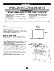
... must be performed in masonry, use this device on a motorized door without fuse links installed.
5. Mount the release device on releasing device. Installation Requirements: Intended for "Indoor Dry" locations; all wiring must be used if mounting release device into masonry.
6. WARNING
I N S TA L L AT I O N
IMPORTANT INSTALLATION INSTRUCTIONS
WARNING To reduce the risk of 40 lbs.
LM21XP Manual - Page 5
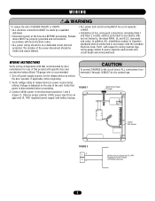
...Verify voltage rating of release device to , the latest NFPA, UL and N.E.C. Observe proper polarity. 24Vdc power input from an approved UL 1481 regulated power supply with Battery Backup
5
standards and codes.
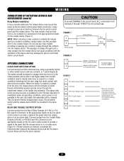
The location of the power disconnect should be dry contact type. WIRING INSTRUCTIONS
Verify wiring configuration with specific door and accessories being utilized...
LM21XP Manual - Page 6
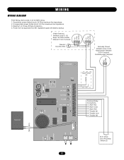
... LED6 LED2 LED7
2W_OP 2W_FAULT NC_FAULT
CL_LIMIT
GND_FAULT
Common Relay Connections
Alarm NC Alarm Com Alarm NO Trouble NC Trouble Com Trouble NO
K3 K1
(YE) (GY)
P1
+
SW2 SW3
POWER ON
LED 1 DISABLE
LED 3
N.O. Close Door Proximity Switch (2)
6 Supervised, power limited circuit, 20 Ohm maximum line impedance. 2. Unsupervised, power limited circuit, 20 Ohm...
LM21XP Manual - Page 7
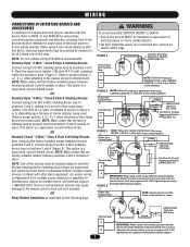
... removing the factory-installed jumper between terminal positions 5 and 6 remains in place. OR
Relay Module Installation as described on multiple doors, call technical support, 1-888-528-...+ IN
COM NO - Normally Open "2-Wire," Class B Style A Initiating Devices
Connect wiring from multiple smoke detectors or signaling for instructions concerning proper placement and detection coverage...
LM21XP Manual - Page 8
... Output 12 Common 13 N/O Alarm Relay Output 14 N/C Trouble Output 15 Trouble Common 16 N/O Trouble Output
Proximity Switch Part No. Fail-safe operation is maintained under all necessary connections to engage when the door is in the same room. NOTE: When choosing a relay module to activate the release device in an alarm condition, always select one...
LM21XP Manual - Page 9
... 3 is unused and should remain in the OFF position. WIRING
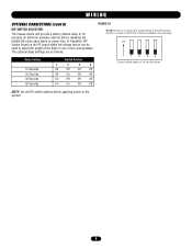
OPTIONAL CONNECTIONS (cont'd)
DIP SWITCH SELECTION
The release device will provide a factory default delay of 10 seconds shown. The optional delay settings are as follows:
Delay Setting
10 Seconds 20 Seconds 30 Seconds 60 Seconds
Switch Position
1
2
3
4
Off
Off
Off
Off
Off
On...
LM21XP Manual - Page 10
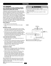
...motor operator, lower the door to fully open or closed position.
2. Reset the test button.
3. Reset the door per door manufacturer's instructions. CLEAR FIRE DOOR OPENING AND PROHIBIT TRAFFIC THROUGH DOOR OPENING WHILE TESTING! Press the "Reset" button on the fire door or counter fire door installation. All tests may not apply. Release test button.
2. Make sure door is in order to...
LM21XP Manual - Page 11
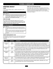
... fire door or shutter is not grounded properly, and a short to the table below for correct wiring instructions. If not lit, refer to the Smoke Detector Installation section on pages 7 and 8 of the ancillary devices/loops (smoke detector, annunciator, etc.) is closed position, activating the proximity switch. Conversely, the release device will not release the...
LM21XP Manual - Page 12
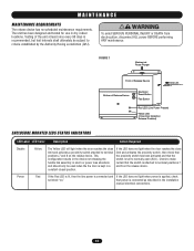
... least once every 90 days is attached to normally open (N.O.). that power is set to terminal positions 7 and 8 on the release device.
The unit has been designed and tested for use in the installation
manual electrical connections.
12
If the LED does not light when the door reaches the close limit and activates a proximity switch attached...
LM21XP Manual - Page 13
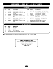
HOW TO ORDER REPAIR PARTS
OUR LARGE SERVICE ORGANIZATION SPANS AMERICA Installation and service information call our TOLL FREE number: 1-888-528-7870
13 ACCESSORIES AND REPLACEMENT PARTS
ITEM 1 2
PART # LM8100 LM8100T
... End-of-Line Relay - 120Vac
REPLACEMENT PARTS
ITEM 1 2 3 4
PART #
DESCRIPTION
LMRK
Reset Knob
LMELH
End Link
01-32046 Owner's Manual
LMEOLRES-10 End-of-Line Resistor,...
LM21XP Manual - Page 14
...-B
4WT-B
#1424
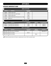
HEAT DETECTORS
MODEL NO. PAM-1
LIFTMASTER NO. DESCRIPTION
LMEOLRES-10 10 kOhm End-of-Line Resistor LMEOLR1224 End-of-Line Relay LMEOLR120 End-of-Line Relay
SYSTEM SENSOR MODEL NO. LMEOLRES-10
NOTE: Certain accessories above will require a separate power source. Refer to product manual.
14
APPENDIX
ACCESSORY COMPATIBILITY GUIDE
SMOKE DETECTORS
MODEL NO.
LiftMaster LM21XP Reviews
We have not received any reviews for LiftMaster yet.