LM21XP Manual
Page 2
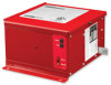
... on rolling doors, single-slide and center-parting level and inclined track doors. INTRODUCTION GENERAL DESCRIPTION The LiftMaster® LM21XP Release Device is designated to the possibility of serious injury or death if you do not comply with the...WIRING Wiring Instructions 5 Wiring Diagram 6 Connections of Initiating Devices and Accessories 7-8 Optional Connections 8-9 TESTING Test Procedures 10 TROUBLESHOOTING Operational Checklist 11 MAINTENANCE Maintenance Requirements 12 Enclosure Mounted LEDs Status Indicators 12 ACCESSORIES AND REPLACEMENT PARTS 13 APPENDIX 14 OPERATOR...
... on rolling doors, single-slide and center-parting level and inclined track doors. INTRODUCTION GENERAL DESCRIPTION The LiftMaster® LM21XP Release Device is designated to the possibility of serious injury or death if you do not comply with the...WIRING Wiring Instructions 5 Wiring Diagram 6 Connections of Initiating Devices and Accessories 7-8 Optional Connections 8-9 TESTING Test Procedures 10 TROUBLESHOOTING Operational Checklist 11 MAINTENANCE Maintenance Requirements 12 Enclosure Mounted LEDs Status Indicators 12 ACCESSORIES AND REPLACEMENT PARTS 13 APPENDIX 14 OPERATOR...
LM21XP Manual
Page 11
... 8. voltage should not be picked up from terminal board positions 3 and 4) is disabled and will always release the fusible link assembly when powered or reset. TROUBLESHOOTING OPERATIONAL CHECKLIST POWER Is the red LED, labeled "Power," located on to the smoke detectors to reset, then depress the auxiliary reset button to reset...
... 8. voltage should not be picked up from terminal board positions 3 and 4) is disabled and will always release the fusible link assembly when powered or reset. TROUBLESHOOTING OPERATIONAL CHECKLIST POWER Is the red LED, labeled "Power," located on to the smoke detectors to reset, then depress the auxiliary reset button to reset...

