LM21XP Manual
Page 7
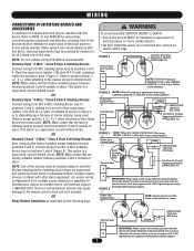
... @ 1/2 watt Supervisory Resistor (LMEOLRES-10) 4 (-) FIGURE 6 IMPORTANT: When using 4-wire smoke detectors with other 2-wire 24Vdc smoke detectors. OR Normally Open "4-Wire," Class B Style A Initiating Devices Connect wiring from N/O initiating device loop to positions 3 and 4. Power from N/C 4-Wire initiating device loop to...wire smoke detector. • DO NOT install this device, electrical supervision must be installed with this device on multiple doors, call technical support, 1-888-528-7870. NOTE: Make certain that the factory-installed resistor between devices may be ...
... @ 1/2 watt Supervisory Resistor (LMEOLRES-10) 4 (-) FIGURE 6 IMPORTANT: When using 4-wire smoke detectors with other 2-wire 24Vdc smoke detectors. OR Normally Open "4-Wire," Class B Style A Initiating Devices Connect wiring from N/O initiating device loop to positions 3 and 4. Power from N/C 4-Wire initiating device loop to...wire smoke detector. • DO NOT install this device, electrical supervision must be installed with this device on multiple doors, call technical support, 1-888-528-7870. NOTE: Make certain that the factory-installed resistor between devices may be ...
LM21XP Manual
Page 10
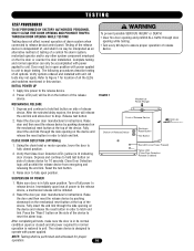
...CAUTION • Clear fire door opening and prohibit ALL traffic through door opening on side of , and shall in order to begin testing. Raise door to operate with unit. After completing all tests, make sure the door is designed to fully open position. Complete testing and normal... not apply. Power LED (red) will be performed and witnessed for 10 seconds. Reset the door per door manufacturer's instructions. CLEAR FIRE DOOR OPENING AND PROHIBIT TRAFFIC THROUGH DOOR OPENING WHILE TESTING! Turn off all power required for location of power to the release device. 2. Reset...
...CAUTION • Clear fire door opening and prohibit ALL traffic through door opening on side of , and shall in order to begin testing. Raise door to operate with unit. After completing all tests, make sure the door is designed to fully open position. Complete testing and normal... not apply. Power LED (red) will be performed and witnessed for 10 seconds. Reset the door per door manufacturer's instructions. CLEAR FIRE DOOR OPENING AND PROHIBIT TRAFFIC THROUGH DOOR OPENING WHILE TESTING! Turn off all power required for location of power to the release device. 2. Reset...
LM21XP Manual
Page 11
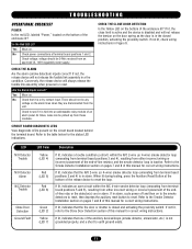
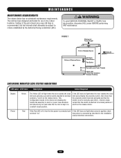
... 8 of -line resistor, and the smoke detector loop is in alarm. Are the Alarm Inputs correct? LED N/O Detector Trouble N/O Detector Alarm N/C Detector Trouble Close Door Detection Ground Fault LED Color Yellow (LED 4) Red (LED 5) Red (LED 6) Green (LED 2) Yellow (LED 7) Description If lit, indicates a trouble condition ...grounded properly, and a short to see if it is in the closed and activating the proximity switch. If lit, indicates an open circuit within the N/O 2-wire (or 4-wire) smoke detector loop (emanating from terminal board positions 3 and 4), resulting from these modules. ...
... 8 of -line resistor, and the smoke detector loop is in alarm. Are the Alarm Inputs correct? LED N/O Detector Trouble N/O Detector Alarm N/C Detector Trouble Close Door Detection Ground Fault LED Color Yellow (LED 4) Red (LED 5) Red (LED 6) Green (LED 2) Yellow (LED 7) Description If lit, indicates a trouble condition ...grounded properly, and a short to see if it is in the closed and activating the proximity switch. If lit, indicates an open circuit within the N/O 2-wire (or 4-wire) smoke detector loop (emanating from terminal board positions 3 and 4), resulting from these modules. ...
LM21XP Manual
Page 12
...least once every 90 days is connected as described in alarm or power loss situations and should only be subject to normally open (N.O.). This configuration results in the device not releasing the fusible link assembly in the installation manual electrical connections. 12 Power Red.... WARNING MAINTENANCE WARNING CAUTION MAINTENANCE REQUIREMENTS The release device has no scheduled maintenance requirements. If the LED does not light when the door reaches the close limit and activates a proximity switch attached to terminal positions 7 and 8 on the release device. The unit has...
...least once every 90 days is connected as described in alarm or power loss situations and should only be subject to normally open (N.O.). This configuration results in the device not releasing the fusible link assembly in the installation manual electrical connections. 12 Power Red.... WARNING MAINTENANCE WARNING CAUTION MAINTENANCE REQUIREMENTS The release device has no scheduled maintenance requirements. If the LED does not light when the door reaches the close limit and activates a proximity switch attached to terminal positions 7 and 8 on the release device. The unit has...

