8550 Manual
Page 1
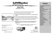
...Drive Garage Door Opener Model 8550 FOR RESIDENTIAL USE ONLY Write down the following information for installation instructions. . www.liftmaster.com The Chamberlain Group, Inc. 845 Larch Avenue Elmhurst, Illinois 60126-1196 Contents BELT DRIVE GARAGE DOOR OPENER.. 1 PREPARATION 2 ASSEMBLY 4 INSTALLATION 6-13 INSTALL THE DOOR ...;®2.0 accessories. ■ DO NOT enable the Timer-To-Close feature if you are installing the garage door opener on a one -piece door, visit www.liftmaster.com for future reference: Serial Number: Date of Purchase: ■ Please read this manual and the...
...Drive Garage Door Opener Model 8550 FOR RESIDENTIAL USE ONLY Write down the following information for installation instructions. . www.liftmaster.com The Chamberlain Group, Inc. 845 Larch Avenue Elmhurst, Illinois 60126-1196 Contents BELT DRIVE GARAGE DOOR OPENER.. 1 PREPARATION 2 ASSEMBLY 4 INSTALLATION 6-13 INSTALL THE DOOR ...;®2.0 accessories. ■ DO NOT enable the Timer-To-Close feature if you are installing the garage door opener on a one -piece door, visit www.liftmaster.com for future reference: Serial Number: Date of Purchase: ■ Please read this manual and the...
8550 Manual
Page 2
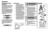
... locks and remove ALL ropes connected to garage door BEFORE installation and operating garage door opener to avoid entanglement. 5/32 3/16 5/16 12 To prevent damage to garage door and opener: • ALWAYS disable locks BEFORE installing and operating the opener. • ONLY operate garage door opener at 120 V, 60 Hz to avoid ... or center bearing plate in the way of the door. An unbalanced garage door may not work properly. 5. See installing the Header Bracket section. Check the Door 1. If your garage door and/or the garage door opener if you see this manual. Any gap between the...
... locks and remove ALL ropes connected to garage door BEFORE installation and operating garage door opener to avoid entanglement. 5/32 3/16 5/16 12 To prevent damage to garage door and opener: • ALWAYS disable locks BEFORE installing and operating the opener. • ONLY operate garage door opener at 120 V, 60 Hz to avoid ... or center bearing plate in the way of the door. An unbalanced garage door may not work properly. 5. See installing the Header Bracket section. Check the Door 1. If your garage door and/or the garage door opener if you see this manual. Any gap between the...
8550 Manual
Page 3
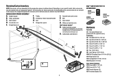
... Safety labels and literature H L M J N O I . Curved door arm E. Sprocket cover and screws K. The instructions for reference and your garage door opener. GARAGE DOOR OPENER ASSEMBLY A. Door control M. Pulley and bracket C. Overview/Carton Inventory NOTE: Accessories will vary ... these accessories will be included with your product may look different. Belt L. Trolley G. Depending on the garage door opener model purchased. Door bracket D. Garage door opener K J. Safety reversing sensors with the sprocket cover] Installation H2 Hex Bolt 5/16"-18 x 7/8" ...
... Safety labels and literature H L M J N O I . Curved door arm E. Sprocket cover and screws K. The instructions for reference and your garage door opener. GARAGE DOOR OPENER ASSEMBLY A. Door control M. Pulley and bracket C. Overview/Carton Inventory NOTE: Accessories will vary ... these accessories will be included with your product may look different. Belt L. Trolley G. Depending on the garage door opener model purchased. Door bracket D. Garage door opener K J. Safety reversing sensors with the sprocket cover] Installation H2 Hex Bolt 5/16"-18 x 7/8" ...
8550 Manual
Page 4
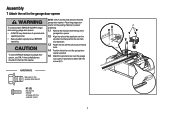
... to finger scratching. HARDWARE Mounted in the top of sprocket while garage door opener. opener sprocket. 1.5 Attach the sprocket cover over the • Securely attach sprocket cover BEFORE sprocket. Place the garage door opener on the packing material to prevent H1 To avoid possible SERIOUS INJURY to garage door opener, use the bolts removed from the rail, belt, operating. operating...
... to finger scratching. HARDWARE Mounted in the top of sprocket while garage door opener. opener sprocket. 1.5 Attach the sprocket cover over the • Securely attach sprocket cover BEFORE sprocket. Place the garage door opener on the packing material to prevent H1 To avoid possible SERIOUS INJURY to garage door opener, use the bolts removed from the rail, belt, operating. operating...
8550 Manual
Page 6
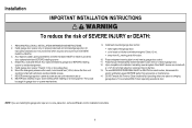
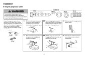
NEVER connect garage door opener to power source until instructed to avoid entanglement. 5. Install wall-mounted garage door control: • within reach, but at least 6 feet (1.83 m) above floor. 6. Door MUST reverse on.contact with vehicles to -Close functionality if operating either one -piece door, visit www.liftmaster.com for installation instructions. 6 Disable ALL locks and remove ALL ropes...
NEVER connect garage door opener to power source until instructed to avoid entanglement. 5. Install wall-mounted garage door control: • within reach, but at least 6 feet (1.83 m) above floor. 6. Door MUST reverse on.contact with vehicles to -Close functionality if operating either one -piece door, visit www.liftmaster.com for installation instructions. 6 Disable ALL locks and remove ALL ropes...
8550 Manual
Page 7
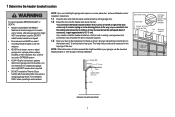
...(1 cm). This height will provide travel as shown. NOTE: If the total number of which are installing the garage door opener on a one -piece or swinging garage doors. 1 Determine the header bracket location To prevent possible SERIOUS INJURY or DEATH: • Header bracket MUST be ... the door. Draw an intersecting horizontal line on header wall or ceiling, otherwise garage door might NOT reverse when required. • DO NOT enable the Timer-to-Close functionality if operating either one -piece door, visit www.liftmaster.com for the top edge of Garage Door 2x4 OPTIONAL...
...(1 cm). This height will provide travel as shown. NOTE: If the total number of which are installing the garage door opener on a one -piece or swinging garage doors. 1 Determine the header bracket location To prevent possible SERIOUS INJURY or DEATH: • Header bracket MUST be ... the door. Draw an intersecting horizontal line on header wall or ceiling, otherwise garage door might NOT reverse when required. • DO NOT enable the Timer-to-Close functionality if operating either one -piece door, visit www.liftmaster.com for the top edge of Garage Door 2x4 OPTIONAL...
8550 Manual
Page 9
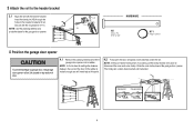
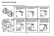
... a 2x4 (laid flat) under the rail. Slide the outer trolley toward the garage door opener. 3 Attach the rail to garage door, rest garage door opener rail on 2x4 placed on top section of door. 4.1 Remove the packing material and lift the garage door opener onto a ladder. NOTE: If the door hits the trolley when it is raised, pull the trolley release arm down...
... a 2x4 (laid flat) under the rail. Slide the outer trolley toward the garage door opener. 3 Attach the rail to garage door, rest garage door opener rail on 2x4 placed on top section of door. 4.1 Remove the packing material and lift the garage door opener onto a ladder. NOTE: If the door hits the trolley when it is raised, pull the trolley release arm down...
8550 Manual
Page 10
...before installing the garage door opener. 5.2 Make sure the garage door opener is aligned with the bolts (H2), lock door. header bracket. (not provided) H2 H9 H8 10 For ALL installations the garage door opener MUST be different. Measure the distance from a falling garage door opener, fasten it...5/16"-18 H2 (2) Hex Bolt 5/16"- 18x7/8" Hanging the garage door opener will vary depending on your garage. Installation 5 Hang the garage door opener To avoid possible SERIOUS INJURY from each side of the garage door opener to the support bracket. 5.3 Cut both pieces of the hanging...
...before installing the garage door opener. 5.2 Make sure the garage door opener is aligned with the bolts (H2), lock door. header bracket. (not provided) H2 H9 H8 10 For ALL installations the garage door opener MUST be different. Measure the distance from a falling garage door opener, fasten it...5/16"-18 H2 (2) Hex Bolt 5/16"- 18x7/8" Hanging the garage door opener will vary depending on your garage. Installation 5 Hang the garage door opener To avoid possible SERIOUS INJURY from each side of the garage door opener to the support bracket. 5.3 Cut both pieces of the hanging...
8550 Manual
Page 13
... Door Arm (Groove facing out) Curved Door Arm INCORRECT Straight Door Arm Curved Door Arm 9.1 Close the door. Disconnect the trolley by 9.2 Attach the straight door arm to the trolley IMPORTANT: The groove on the straight door arm MUST face away from the curved door arm. Attach with the curved door arm. Select two aligned holes (as toward the garage door opener...
... Door Arm (Groove facing out) Curved Door Arm INCORRECT Straight Door Arm Curved Door Arm 9.1 Close the door. Disconnect the trolley by 9.2 Attach the straight door arm to the trolley IMPORTANT: The groove on the straight door arm MUST face away from the curved door arm. Attach with the curved door arm. Select two aligned holes (as toward the garage door opener...
8550 Manual
Page 14
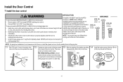
...to protrude from the wall. NOTE: Older LiftMaster accessories and third party products are no obstructions to either screw. 7/16" (11 mm) PRE-WIRED INSTALLATIONS: Choose Wall any other Security+®2.0 door controls. • Install door control within sight of garage door, out of reach of children at a ...H16 (2) Drywall Anchors NOTE: For gang box installations it can be seen clearly, is properly adjusted, and there are not compatible.Your garage door opener is compatible with up to 2 Smart Control Panels or 4 of any two wires to connect, note which wires H16 GANG BOX are...
...to protrude from the wall. NOTE: Older LiftMaster accessories and third party products are no obstructions to either screw. 7/16" (11 mm) PRE-WIRED INSTALLATIONS: Choose Wall any other Security+®2.0 door controls. • Install door control within sight of garage door, out of reach of children at a ...H16 (2) Drywall Anchors NOTE: For gang box installations it can be seen clearly, is properly adjusted, and there are not compatible.Your garage door opener is compatible with up to 2 Smart Control Panels or 4 of any two wires to connect, note which wires H16 GANG BOX are...
8550 Manual
Page 15
... to the red and white terminals on the garage door opener. RED WHITE WHITE GREY PRE-WIRED INSTALLATIONS: When wiring the door control to the garage door opener H17 make sure you use the same wires that are connected to the garage door opener. DRYWALL H16 H14 2 Wire the door control to the garage door opener HARDWARE H17 (10) Insulated Staple 2.1 Run the white...
... to the red and white terminals on the garage door opener. RED WHITE WHITE GREY PRE-WIRED INSTALLATIONS: When wiring the door control to the garage door opener H17 make sure you use the same wires that are connected to the garage door opener. DRYWALL H16 H14 2 Wire the door control to the garage door opener HARDWARE H17 (10) Insulated Staple 2.1 Run the white...
8550 Manual
Page 17
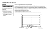
...DEATH from closing , the door will stop and reverse to the full open position, and the garage door opener lights will move in the down until the garage door opener has completed 5 cycles upon power up. The sleep mode shuts the garage door opener down direction. The garage door opener will not go into the...Safety Reversing Sensor 6" (15 cm) max. The sending sensor (with an amber LED) transmits an invisible light beam to the garage door opener BEFORE installing the safety reversing sensor. The sleep mode is unobstructed. Safety Reversing Sensor 6" (15 cm) max. When installing the...
...DEATH from closing , the door will stop and reverse to the full open position, and the garage door opener lights will move in the down until the garage door opener has completed 5 cycles upon power up. The sleep mode shuts the garage door opener down direction. The garage door opener will not go into the...Safety Reversing Sensor 6" (15 cm) max. The sending sensor (with an amber LED) transmits an invisible light beam to the garage door opener BEFORE installing the safety reversing sensor. The sleep mode is unobstructed. Safety Reversing Sensor 6" (15 cm) max. When installing the...
8550 Manual
Page 19
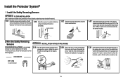
... bracket (not provided) or wood black to raise the sensor bracket if needed. 1.1C Carefully measure the position of both sensors to the garage door opener. Twist the white/black wires together. Attach the wire to the wall and ceiling with a screwdriver tip. Separate the wires. Insert the ... to the floor using concrete anchors (not provided). (not provided) IGWnsaairdlalege 1.3C Slide the carriage bolt (H12) into the grey terminal on the garage door opener. H12 1.4C Insert the bolt through the hole in the tab with the staples (H17). 2.2A Strip 7/16 inch (11 mm) of wires...
... bracket (not provided) or wood black to raise the sensor bracket if needed. 1.1C Carefully measure the position of both sensors to the garage door opener. Twist the white/black wires together. Attach the wire to the wall and ceiling with a screwdriver tip. Separate the wires. Insert the ... to the floor using concrete anchors (not provided). (not provided) IGWnsaairdlalege 1.3C Slide the carriage bolt (H12) into the grey terminal on the garage door opener. H12 1.4C Insert the bolt through the hole in the tab with the staples (H17). 2.2A Strip 7/16 inch (11 mm) of wires...
8550 Manual
Page 20
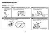
...or remove the wires from each end. Make sure that are connected to the white/black safety sensor wires to the white terminal on the garage door opener. Insert the wires that you choose the same color pre-installed wires for the safety reversing sensors. Twist the like-colored wires together. ...2.5B Insert the wires connected to the white safety sensor wires to the grey terminal on the garage door opener. Choose two of the pre-installed wires and strip 7/16 inch (11 mm) of insulation from each end of insulation from each sensor. ...
...or remove the wires from each end. Make sure that are connected to the white/black safety sensor wires to the white terminal on the garage door opener. Insert the wires that you choose the same color pre-installed wires for the safety reversing sensors. Twist the like-colored wires together. ...2.5B Insert the wires connected to the white safety sensor wires to the grey terminal on the garage door opener. Choose two of the pre-installed wires and strip 7/16 inch (11 mm) of insulation from each end of insulation from each sensor. ...
8550 Manual
Page 21
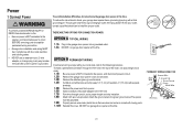
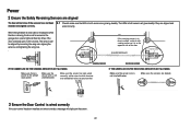
... OPTIONS FOR CONNECTION POWER: OPTION A TYPICAL WIRING 1.1A Plug in the garage door opener into a grounded outlet. 1.2A DO NOT run garage door opener at this time. To avoid installation difficulties, do not activate the garage door opener at this time. Attach the ground wire to the green ground screw.The...wires and strip away 1/2" (1 cm) of electric shock, your local code, refer to the following procedure. Be sure the opener is required by your garage door opener has a grounding type plug with wire nuts provided. To make it fit outlet. OPTION B PERMANENT WIRING If permanent wiring is...
... OPTIONS FOR CONNECTION POWER: OPTION A TYPICAL WIRING 1.1A Plug in the garage door opener into a grounded outlet. 1.2A DO NOT run garage door opener at this time. To avoid installation difficulties, do not activate the garage door opener at this time. Attach the ground wire to the green ground screw.The...wires and strip away 1/2" (1 cm) of electric shock, your local code, refer to the following procedure. Be sure the opener is required by your garage door opener has a grounding type plug with wire nuts provided. To make it fit outlet. OPTION B PERMANENT WIRING If permanent wiring is...
8550 Manual
Page 22
... not close . IF THE GREEN LED ON THE RECEIVING SENSOR IS NOT GLOWING: Make sure the sensor wire is already open, it is power to the garage door opener. If the door is not shorted/broken. The sensors can be aligned by loosening the wing nuts, aligning the sensors, and tightening the wing...the receiving sensor is in both sensors are aligned. Make sure the sensor wire is closing, the door will reverse and the garage door opener lights will display on the opposite side of the door. (invisible light beam) Green LED SENDING SENSOR RECEIVING SENSOR IF THE AMBER LED ON THE SENDING ...
... not close . IF THE GREEN LED ON THE RECEIVING SENSOR IS NOT GLOWING: Make sure the sensor wire is already open, it is power to the garage door opener. If the door is not shorted/broken. The sensors can be aligned by loosening the wing nuts, aligning the sensors, and tightening the wing...the receiving sensor is in both sensors are aligned. Make sure the sensor wire is closing, the door will reverse and the garage door opener lights will display on the opposite side of the door. (invisible light beam) Green LED SENDING SENSOR RECEIVING SENSOR IF THE AMBER LED ON THE SENDING ...
8550 Manual
Page 23
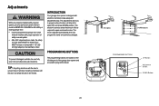
...the left side panel of the garage door opener and are made, the safety reversal system MUST be tested. To prevent damage to vehicles, be changed. If anything interferes with the door's upward travel , it will stop in the open door provides adequate clearance. Adjustments Without ...sense the amount of force required to make setup and adjustments easy. Door MUST reverse on floor. INTRODUCTION Your garage door opener is adjusted automatically when you to program where the door will reverse. UP (Open) DOWN (Close) PROGRAMMING BUTTONS UP Button Adjustment Button DOWN Button ...
...the left side panel of the garage door opener and are made, the safety reversal system MUST be tested. To prevent damage to vehicles, be changed. If anything interferes with the door's upward travel , it will stop in the open door provides adequate clearance. Adjustments Without ...sense the amount of force required to make setup and adjustments easy. Door MUST reverse on floor. INTRODUCTION Your garage door opener is adjusted automatically when you to program where the door will reverse. UP (Open) DOWN (Close) PROGRAMMING BUTTONS UP Button Adjustment Button DOWN Button ...
8550 Manual
Page 24
...cycle using the remote control or the UP and DOWN buttons. press and release the DOWN Button will begin to flash. Adjustment Button. The garage door opener lights will fl ash twice and the UP Button will begin to page 18). The the UP Button begins to NOTE: The UP and ...DOWN Buttons can be garage door opener lights will begin to flash. * If the garage door opener lights are flashing 5 times during the steps for Program the Travel, the safety reversing sensors are flashing 10 times during the...
...cycle using the remote control or the UP and DOWN buttons. press and release the DOWN Button will begin to flash. Adjustment Button. The garage door opener lights will fl ash twice and the UP Button will begin to page 18). The the UP Button begins to NOTE: The UP and ...DOWN Buttons can be garage door opener lights will begin to flash. * If the garage door opener lights are flashing 5 times during the steps for Program the Travel, the safety reversing sensors are flashing 10 times during the...
8550 Manual
Page 25
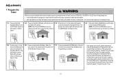
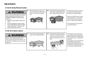
...8226; After ANY adjustments are no more than 6 inches [15 cm] above the floor), call a trained door systems technician. 3 Test the Protector System 3.1 Open the door. The garage door opener will flash 10 times. The door MUST reverse when it makes contact with the 1-1/2 inch board, remove the board and... control if the LED in the path of the door. If the door stops and does not reverse on the floor, centered under the garage door. 2.2 Press the remote control push button to close the door. Place the garage door opener carton in either safety reversing sensor is off (alerting...
...8226; After ANY adjustments are no more than 6 inches [15 cm] above the floor), call a trained door systems technician. 3 Test the Protector System 3.1 Open the door. The garage door opener will flash 10 times. The door MUST reverse when it makes contact with the 1-1/2 inch board, remove the board and... control if the LED in the path of the door. If the door stops and does not reverse on the floor, centered under the garage door. 2.2 Press the remote control push button to close the door. Place the garage door opener carton in either safety reversing sensor is off (alerting...
8550 Manual
Page 26
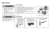
... terminals facing out. 1.4 Connect red (+) and black (-) wires from the garage door opener to persons: • Disconnect ALL electric and battery power BEFORE performing ANY service or maintenance. • Use ONLY LiftMaster part # 485LM for the green Battery Status LED to start flashing before proceeding... to fully charge. NOTE: Make sure the garage door opener is charging. 26 ALWAYS wear protective gloves and eye protection when...
... terminals facing out. 1.4 Connect red (+) and black (-) wires from the garage door opener to persons: • Disconnect ALL electric and battery power BEFORE performing ANY service or maintenance. • Use ONLY LiftMaster part # 485LM for the green Battery Status LED to start flashing before proceeding... to fully charge. NOTE: Make sure the garage door opener is charging. 26 ALWAYS wear protective gloves and eye protection when...


