
8550 Manual
Page 1
...liftmaster.com The Chamberlain Group, Inc. 845 Larch Avenue Elmhurst, Illinois 60126-1196 Contents BELT DRIVE GARAGE DOOR OPENER.. 1 PREPARATION 2 ASSEMBLY 4 INSTALLATION 6-13 INSTALL THE DOOR CONTROL.....14-16 INSTALL...installing the garage door opener on a one -piece door, visit www.liftmaster....com for future reference: Serial Number: Date of the garage door opener are required to be used ONLY with MyQ™ and Security✚®2.0 accessories. ■ DO NOT enable the Timer-To-Close feature if you are installing...garage door after installation. ■ The door WILL...
...liftmaster.com The Chamberlain Group, Inc. 845 Larch Avenue Elmhurst, Illinois 60126-1196 Contents BELT DRIVE GARAGE DOOR OPENER.. 1 PREPARATION 2 ASSEMBLY 4 INSTALLATION 6-13 INSTALL THE DOOR CONTROL.....14-16 INSTALL...installing the garage door opener on a one -piece door, visit www.liftmaster....com for future reference: Serial Number: Date of the garage door opener are required to be used ONLY with MyQ™ and Security✚®2.0 accessories. ■ DO NOT enable the Timer-To-Close feature if you are installing...garage door after installation. ■ The door WILL...
8550 Manual
Page 2
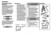
...Needed To prevent possible SERIOUS INJURY or DEATH: • ALWAYS call a trained door systems technician if garage door binds, sticks, or is installed, operated, maintained and tested in strict accordance with the instructions and warnings contained in place, supported entirely by its springs. 3. Read the warnings...you to the possibility of which are under EXTREME tension. • Disable ALL locks and remove ALL ropes connected to garage door BEFORE installation and operating garage door opener to avoid entanglement. 5/32 3/16 5/16 12 To prevent damage to garage door and opener: •...
...Needed To prevent possible SERIOUS INJURY or DEATH: • ALWAYS call a trained door systems technician if garage door binds, sticks, or is installed, operated, maintained and tested in strict accordance with the instructions and warnings contained in place, supported entirely by its springs. 3. Read the warnings...you to the possibility of which are under EXTREME tension. • Disable ALL locks and remove ALL ropes connected to garage door BEFORE installation and operating garage door opener to avoid entanglement. 5/32 3/16 5/16 12 To prevent damage to garage door and opener: •...
8550 Manual
Page 3
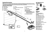
... and handle H. Garage door opener K J. Trolley G. Belt L. Safety labels and literature H L M J N O I . Header bracket B. Pulley and bracket C. Door control M. Safety reversing sensors with the sprocket cover] Installation H2 Hex Bolt 5/16"-18 x 7/8" (4) H3 Lag Screw 5/16"-9 x 1-5/8" (2) H4 Lag Screw 5/16"-18 x 1-5/8" (2) H5 Clevis Pin 5/16" x 2-3/4" (1) H6 Clevis Pin 5/16" x 1-1/4" (1) H7 Clevis Pin...
... and handle H. Garage door opener K J. Trolley G. Belt L. Safety labels and literature H L M J N O I . Header bracket B. Pulley and bracket C. Door control M. Safety reversing sensors with the sprocket cover] Installation H2 Hex Bolt 5/16"-18 x 7/8" (4) H3 Lag Screw 5/16"-9 x 1-5/8" (2) H4 Lag Screw 5/16"-18 x 1-5/8" (2) H5 Clevis Pin 5/16" x 2-3/4" (1) H6 Clevis Pin 5/16" x 1-1/4" (1) H7 Clevis Pin...
8550 Manual
Page 6
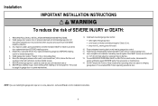
...out of reach of children at ) on wall next to -Close functionality if operating either one -piece door, visit www.liftmaster.com for installation instructions. 6 They could result in SEVERE INJURY or DEATH. 3. Place entrapment warning label on the floor. 13. To ...spring assemblies and other hardware MUST be made by a trained door systems technician BEFORE installing opener. 4. Installation IMPORTANT INSTALLATION INSTRUCTIONS WARNING To reduce the risk of installation, test safety reversal system. Install garage door opener only on a one -piece or swinging garage doors. An ...
...out of reach of children at ) on wall next to -Close functionality if operating either one -piece door, visit www.liftmaster.com for installation instructions. 6 They could result in SEVERE INJURY or DEATH. 3. Place entrapment warning label on the floor. 13. To ...spring assemblies and other hardware MUST be made by a trained door systems technician BEFORE installing opener. 4. Installation IMPORTANT INSTALLATION INSTRUCTIONS WARNING To reduce the risk of installation, test safety reversal system. Install garage door opener only on a one -piece or swinging garage doors. An ...
8550 Manual
Page 7
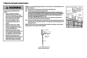
... Concrete anchors MUST be used if mounting header bracket or 2x4 into masonry. • NEVER try to the highest point of travel clearance for installation instructions. 1.1 Close the door and mark the inside vertical centerline of the garage door. 1.2 Extend the line onto the header wall above the...8226; Header bracket MUST be RIGIDLY fastened to -Close functionality if operating either one -piece door, visit www.liftmaster.com for the top edge of the door. If you need to install the header bracket on a 2x4 (on header wall or ceiling, otherwise garage door might NOT reverse when required...
... Concrete anchors MUST be used if mounting header bracket or 2x4 into masonry. • NEVER try to the highest point of travel clearance for installation instructions. 1.1 Close the door and mark the inside vertical centerline of the garage door. 1.2 Extend the line onto the header wall above the...8226; Header bracket MUST be RIGIDLY fastened to -Close functionality if operating either one -piece door, visit www.liftmaster.com for the top edge of the door. If you need to install the header bracket on a 2x4 (on header wall or ceiling, otherwise garage door might NOT reverse when required...

8550 Manual
Page 8
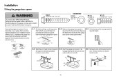
...with the hardware provided (H3). Drill 3/16" pilot holes and fasten bracket securely to a structural support with the hardware provided (H3). OPTION B CEILING INSTALLATION 2.1B Extend the vertical centerline onto the ceiling as shown (with the arrow pointing toward the ceiling). 2.2A Mark the vertical set of Garage Door... ONLY UP Door Spring The nail hole is for ceiling mount). Make sure the arrow is pointing away from the wall. Do not install the header bracket over drywall. The bracket can attach the header bracket either to the wall above the garage door, or to mount ...
...with the hardware provided (H3). Drill 3/16" pilot holes and fasten bracket securely to a structural support with the hardware provided (H3). OPTION B CEILING INSTALLATION 2.1B Extend the vertical centerline onto the ceiling as shown (with the arrow pointing toward the ceiling). 2.2A Mark the vertical set of Garage Door... ONLY UP Door Spring The nail hole is for ceiling mount). Make sure the arrow is pointing away from the wall. Do not install the header bracket over drywall. The bracket can attach the header bracket either to the wall above the garage door, or to mount ...
8550 Manual
Page 10
...the door hits the rail, raise the hardware (not provided). Concrete anchors MUST be connected to structural supports. Below are three example installations. Installation 5 Hang the garage door opener To avoid possible SERIOUS INJURY from each side of the garage door opener to the support bracket.... to the 5.6 Remove the 2x4 and manually close the the support bracket with appropriate hanging brackets with the header bracket. Your installation may be different. Finished Ceiling 5.1 On finished ceilings, use the lag screws (H3) to attach a support bracket (not provided) to...
...the door hits the rail, raise the hardware (not provided). Concrete anchors MUST be connected to structural supports. Below are three example installations. Installation 5 Hang the garage door opener To avoid possible SERIOUS INJURY from each side of the garage door opener to the support bracket.... to the 5.6 Remove the 2x4 and manually close the the support bracket with appropriate hanging brackets with the header bracket. Your installation may be different. Finished Ceiling 5.1 On finished ceilings, use the lag screws (H3) to attach a support bracket (not provided) to...
8550 Manual
Page 11
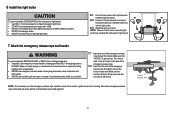
... light lens and rotate the light lens down. If rope knot becomes untied, you could result in the trolley release arm. Trolley Release Arm 11 6 Install the light bulbs 6.1 Pull on the top center of short neck or speciality light • DO NOT use short neck or specialty light bulbs. NOTE...
... light lens and rotate the light lens down. If rope knot becomes untied, you could result in the trolley release arm. Trolley Release Arm 11 6 Install the light bulbs 6.1 Pull on the top center of short neck or speciality light • DO NOT use short neck or specialty light bulbs. NOTE...
8550 Manual
Page 12
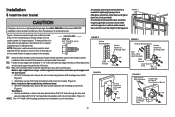
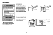
Contact your door manufacturer for direct attachment of the door. 8.3 Mark, drill holes and install as follows, depending on your garage door manufacturer for the header bracket installation. A vertical reinforcement brace should be long enough to be secured to two or three vertical ... to the next step. FIGURE 1 Figure 1 shows one piece of Garage Door 12 Installation 8 Install the door bracket Fiberglass, aluminum or lightweight steel garage doors WILL REQUIRE reinforcement BEFORE installation of Garage Door 8.1 Center the door bracket on wood doors. For the vertical brace,...
Contact your door manufacturer for direct attachment of the door. 8.3 Mark, drill holes and install as follows, depending on your garage door manufacturer for the header bracket installation. A vertical reinforcement brace should be long enough to be secured to two or three vertical ... to the next step. FIGURE 1 Figure 1 shows one piece of Garage Door 12 Installation 8 Install the door bracket Fiberglass, aluminum or lightweight steel garage doors WILL REQUIRE reinforcement BEFORE installation of Garage Door 8.1 Center the door bracket on wood doors. For the vertical brace,...
8550 Manual
Page 14
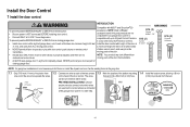
... a 5/32 inch (4 mm) hole. (3 mm) to door travel. NOTE: Your product may look different than moving parts of door. Install the Door Control 1 Install the door control INTRODUCTION Compatible with door control push buttons or remote control transmitters. on the back of closing garage door: accessories. a minimum... wires H16 GANG BOX are used so the correct wires are connected at (1.5 m), and away from the wall. NOTE: Older LiftMaster accessories and third party products are no obstructions to protrude from ALL moving parts of the wire and separate the wires.
... a 5/32 inch (4 mm) hole. (3 mm) to door travel. NOTE: Your product may look different than moving parts of door. Install the Door Control 1 Install the door control INTRODUCTION Compatible with door control push buttons or remote control transmitters. on the back of closing garage door: accessories. a minimum... wires H16 GANG BOX are used so the correct wires are connected at (1.5 m), and away from the wall. NOTE: Older LiftMaster accessories and third party products are no obstructions to protrude from ALL moving parts of the wire and separate the wires.
8550 Manual
Page 15
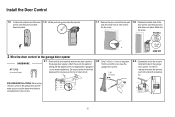
... Control k 1.5 Position the bottom hole of the door control over the screw and slide down into place. RED WHITE WHITE GREY PRE-WIRED INSTALLATIONS: When wiring the door control to the garage door opener H17 make sure you use the same wires that are connected to the garage door ... up and mark the top hole. 1.7 Remove the door control from the wall and drill a 5/32 inch (4 mm) hole for gang box or pre-wired installations). Attach the wire to the wall and ceiling with the staples (H17) (not applicable for the top screw. 1.8 Position the bottom hole of the wire...
... Control k 1.5 Position the bottom hole of the door control over the screw and slide down into place. RED WHITE WHITE GREY PRE-WIRED INSTALLATIONS: When wiring the door control to the garage door opener H17 make sure you use the same wires that are connected to the garage door ... up and mark the top hole. 1.7 Remove the door control from the wall and drill a 5/32 inch (4 mm) hole for gang box or pre-wired installations). Attach the wire to the wall and ceiling with the staples (H17) (not applicable for the top screw. 1.8 Position the bottom hole of the wire...

8550 Manual
Page 16
Install the Door Control 3 Attach the warning labels 3.1 Attach the entrapment warning label on the wall near the door control with tacks or staples. 3.2 Attach the manual release/safety reverse test label in a visible location on the inside of the garage door. 16
Install the Door Control 3 Attach the warning labels 3.1 Attach the entrapment warning label on the wall near the door control with tacks or staples. 3.2 Attach the manual release/safety reverse test label in a visible location on the inside of the garage door. 16
8550 Manual
Page 17
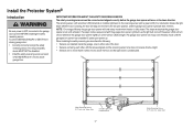
... completed 5 cycles upon power up. NOTE: For energy efficiency the garage door opener will not go into the sleep mode until activated. Install the Protector System® Introduction Be sure power is fully closed. above the floor and the light beam is NO HIGHER than 6 inches... (15 cm) above floor IMPORTANT INFORMATION ABOUT THE SAFETY REVERSING SENSORS The safety reversing sensors must be disabled. • Install the safety reversing sensor so beam is unobstructed. The sending sensor (with an amber LED) transmits an invisible light beam to the garage ...
... completed 5 cycles upon power up. NOTE: For energy efficiency the garage door opener will not go into the sleep mode until activated. Install the Protector System® Introduction Be sure power is fully closed. above the floor and the light beam is NO HIGHER than 6 inches... (15 cm) above floor IMPORTANT INFORMATION ABOUT THE SAFETY REVERSING SENSORS The safety reversing sensors must be disabled. • Install the safety reversing sensor so beam is unobstructed. The sending sensor (with an amber LED) transmits an invisible light beam to the garage ...

8550 Manual
Page 18
...the sensor brackets to be unobstructed. Make sure each bracket has the same amount of clearance so they will not support the sensor bracket a wall installation is needed an extension bracket (not provided) or wood blocks can be attached to the door track, the wall, or the floor. Make sure... there is flush against the wall with the wing nut (H13). Install the Protector System® 1 Install the Safety Reversing Sensors The safety reversing sensors can be used. Make sure the lens is not obstructed by the sensor bracket.
...the sensor brackets to be unobstructed. Make sure each bracket has the same amount of clearance so they will not support the sensor bracket a wall installation is needed an extension bracket (not provided) or wood blocks can be attached to the door track, the wall, or the floor. Make sure... there is flush against the wall with the wing nut (H13). Install the Protector System® 1 Install the Safety Reversing Sensors The safety reversing sensors can be used. Make sure the lens is not obstructed by the sensor bracket.
8550 Manual
Page 19
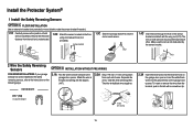
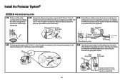
... from both sensors to the garage door opener. H13 2 Wire the Safety Reversing Sensors OPTION A INSTALLATION WITHOUT PRE-WIRING PRE-WIRED INSTALLATIONS: If your garage already has wires installed for the safety reversing sensors, refer to the instructions on both sensors should point toward each other.... white/black wires into the grey terminal on each set of wires. RED WHITE WHITE GREY 19 Install the Protector System® 1 Install the Safety Reversing Sensors OPTION C FLOOR INSTALLATION Use an extension bracket (not provided) or wood black to raise the sensor bracket if needed. ...
... from both sensors to the garage door opener. H13 2 Wire the Safety Reversing Sensors OPTION A INSTALLATION WITHOUT PRE-WIRING PRE-WIRED INSTALLATIONS: If your garage already has wires installed for the safety reversing sensors, refer to the instructions on both sensors should point toward each other.... white/black wires into the grey terminal on each set of wires. RED WHITE WHITE GREY 19 Install the Protector System® 1 Install the Safety Reversing Sensors OPTION C FLOOR INSTALLATION Use an extension bracket (not provided) or wood black to raise the sensor bracket if needed. ...
8550 Manual
Page 20
... to the white terminal on the garage door opener. Not Provided White Yellow (for example) White/Black Safety reversing sensor wires Purple (for example) Pre-installed wires 2.4B At the garage door opener, strip 7/16 inch (11 mm) of insulation from each end of the wires previously chosen for example) Purple... insert or remove the wires from the terminal, push in the tab with wire nuts making sure there is enough wire to reach the pre-installed wires from the wall. 2.2B Separate the safety reversing sensor wires and strip 7/16 inch (11 mm) of insulation from each end. Make sure that...
... to the white terminal on the garage door opener. Not Provided White Yellow (for example) White/Black Safety reversing sensor wires Purple (for example) Pre-installed wires 2.4B At the garage door opener, strip 7/16 inch (11 mm) of insulation from each end of the wires previously chosen for example) Purple... insert or remove the wires from the terminal, push in the tab with wire nuts making sure there is enough wire to reach the pre-installed wires from the wall. 2.2B Separate the safety reversing sensor wires and strip 7/16 inch (11 mm) of insulation from each end. Make sure that...
8550 Manual
Page 21
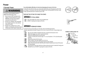
...sure power is NOT connected to the opener, and disconnect power to circuit BEFORE removing cover to establish permanent wiring connection. • Garage door installation and wiring MUST be grounded. 1.9B Properly secure wire under plastic ties so that wire does not come in contact with moving parts. 1.10B ... 1.8B Attach with wire nuts provided. To make it fit outlet. Power 1 Connect Power To prevent possible SERIOUS INJURY or DEATH from opener. 1.6B Install a conduit or flex cable adapter to the 7/8" hole. 1.7B Run wires through the 7/8" hole in the top of the motor unit (according to ...
...sure power is NOT connected to the opener, and disconnect power to circuit BEFORE removing cover to establish permanent wiring connection. • Garage door installation and wiring MUST be grounded. 1.9B Properly secure wire under plastic ties so that wire does not come in contact with moving parts. 1.10B ... 1.8B Attach with wire nuts provided. To make it fit outlet. Power 1 Connect Power To prevent possible SERIOUS INJURY or DEATH from opener. 1.6B Install a conduit or flex cable adapter to the 7/8" hole. 1.7B Run wires through the 7/8" hole in the top of the motor unit (according to ...
8550 Manual
Page 22
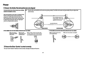
Make sure the sensors are aligned. The LEDs in both sensors will glow steadily if they are aligned and installed and aligned correctly. RED WHITE WHITE GREY 3 Ensure the Door Control is not shorted/broken. If the door is already open, it is on the ... IF THE GREEN LED ON THE RECEIVING SENSOR IS NOT GLOWING: Make sure the sensor wire is wired correctly If the door control has been installed and wired correctly a message will display on the opposite side of the door. (invisible light beam) Green LED SENDING SENSOR RECEIVING SENSOR IF THE AMBER...
Make sure the sensors are aligned. The LEDs in both sensors will glow steadily if they are aligned and installed and aligned correctly. RED WHITE WHITE GREY 3 Ensure the Door Control is not shorted/broken. If the door is already open, it is on the ... IF THE GREEN LED ON THE RECEIVING SENSOR IS NOT GLOWING: Make sure the sensor wire is wired correctly If the door control has been installed and wired correctly a message will display on the opposite side of the door. (invisible light beam) Green LED SENDING SENSOR RECEIVING SENSOR IF THE AMBER...
8550 Manual
Page 23
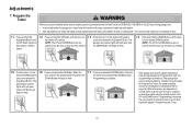
... provides adequate clearance. The electronic controls sense the amount of force required to vehicles, be sure fully open and close (DOWN) position. Adjustments Without a properly installed safety reversal system, persons (particularly small children) could be SERIOUSLY INJURED or KILLED by a closing garage door. • Incorrect adjustment of garage door travel limits...
... provides adequate clearance. The electronic controls sense the amount of force required to vehicles, be sure fully open and close (DOWN) position. Adjustments Without a properly installed safety reversal system, persons (particularly small children) could be SERIOUSLY INJURED or KILLED by a closing garage door. • Incorrect adjustment of garage door travel limits...
8550 Manual
Page 24
... safety reversing sensors are flashing 10 times during the steps for Program the Travel, the programming has timed out. Adjustments 1 Program the Travel Without a properly installed safety reversal system, persons (particularly small children) could be SERIOUSLY INJURED or KILLED by a closing garage door. • Incorrect adjustment of safety reversal system. •...
... safety reversing sensors are flashing 10 times during the steps for Program the Travel, the programming has timed out. Adjustments 1 Program the Travel Without a properly installed safety reversal system, persons (particularly small children) could be SERIOUSLY INJURED or KILLED by a closing garage door. • Incorrect adjustment of safety reversal system. •...


