Clearing Jams Guide
Page 4
...a clean, flat surface. Warning: Do not touch the transfer belt. Remove all the print cartridges. c Slide the image transfer unit out and place it on the handle. 9 Insert the image transfer unit back into place. b Rotate the handle up, ...to its working position. Reinstall all torn paper or other jams. c Lower the lever to unlock the image transfer unit. 8 Look inside the printer. a Align the guides with the insertion grooves and gently slide the ... need more assistance. a Raise the lever to lock the image transfer unit into the printer. Touching the belt will damage the image...
...a clean, flat surface. Warning: Do not touch the transfer belt. Remove all the print cartridges. c Slide the image transfer unit out and place it on the handle. 9 Insert the image transfer unit back into place. b Rotate the handle up, ...to its working position. Reinstall all torn paper or other jams. c Lower the lever to unlock the image transfer unit. 8 Look inside the printer. a Align the guides with the insertion grooves and gently slide the ... need more assistance. a Raise the lever to lock the image transfer unit into the printer. Touching the belt will damage the image...
User's Guide
Page 75
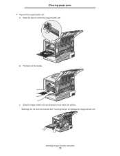
b Pull down on a clean, flat surface. Warning: Do not touch the transfer belt. c Slide the image transfer unit out and place it on the handle. Touching the belt will damage the image transfer unit. Clearing paper jams 7 Remove the image transfer unit. a Raise the lever to unlock the image transfer unit. Clearing image transfer unit jams 75
b Pull down on a clean, flat surface. Warning: Do not touch the transfer belt. c Slide the image transfer unit out and place it on the handle. Touching the belt will damage the image transfer unit. Clearing paper jams 7 Remove the image transfer unit. a Raise the lever to unlock the image transfer unit. Clearing image transfer unit jams 75

Service Manual
Page 5
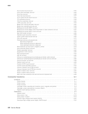
...lines or streaks appear on the page 2-103 White streak in color plane 2-104 Paper wrapped around the second transfer roll 2-104 User troubleshooting for quality 2-105 Second transfer roll service check 2-109 StapleSmart finisher service check 2-111 Tray 1 service check 2-115 Tray 1 media size...Diagnostics mode 3-9 REGISTRATION 3-10 ALIGNMENT MENU 3-11 Setting alignment for color 3-11 Drift Sensors 3-12 MISC TESTS 3-13 Toggle ITU 3-13 Belt Tracking (ITU 4th point adjustment 3-13 Printhead Inst 3-14 PRINT TESTS 3-14 Print Tests (input sources 3-14 Print Quality Pgs 3-15 HARDWARE...
...lines or streaks appear on the page 2-103 White streak in color plane 2-104 Paper wrapped around the second transfer roll 2-104 User troubleshooting for quality 2-105 Second transfer roll service check 2-109 StapleSmart finisher service check 2-111 Tray 1 service check 2-115 Tray 1 media size...Diagnostics mode 3-9 REGISTRATION 3-10 ALIGNMENT MENU 3-11 Setting alignment for color 3-11 Drift Sensors 3-12 MISC TESTS 3-13 Toggle ITU 3-13 Belt Tracking (ITU 4th point adjustment 3-13 Printhead Inst 3-14 PRINT TESTS 3-14 Print Tests (input sources 3-14 Print Quality Pgs 3-15 HARDWARE...
Service Manual
Page 8
...S2/narrow media/transparency/multipurpose feeder sensors removal 4-88 Second transfer roll removal 4-88 System board removal 4-89 Transfer HVPS board removal 4-91 Transfer plate assembly removal 4-94 Vacuum transport belt (VTB) removal 4-95 Vacuum transport belt (VTB) fan removal 4-97 Waste container door removal 4-97...assembly pin locations (black 5-5 System board cabling reference 5-6 Connectors 5-7 System board 5-7 Autoconnect-top 5-18 Autoconnect-bottom 5-19 Transfer high voltage power supply (HVPS 5-20 Developer high voltage power supply (HVPS) board 5-22 viii Service Manual
...S2/narrow media/transparency/multipurpose feeder sensors removal 4-88 Second transfer roll removal 4-88 System board removal 4-89 Transfer HVPS board removal 4-91 Transfer plate assembly removal 4-94 Vacuum transport belt (VTB) removal 4-95 Vacuum transport belt (VTB) fan removal 4-97 Waste container door removal 4-97...assembly pin locations (black 5-5 System board cabling reference 5-6 Connectors 5-7 System board 5-7 Autoconnect-top 5-18 Autoconnect-bottom 5-19 Transfer high voltage power supply (HVPS 5-20 Developer high voltage power supply (HVPS) board 5-22 viii Service Manual
Service Manual
Page 9
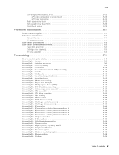
... 6-3 Parts catalog 7-1 How to use this parts catalog 7-1 Assembly 1: Covers 7-2 Assembly 2: Cartridge mounting 7-6 Assembly 3: Fuser assembly 7-7 Assembly 4: Fuser drive 7-10 Assembly 5: Vacuum transport belt (VTB) assembly 7-11 Assembly 6: Transfer 7-12 Assembly 7: Printheads 7-13 Assembly 8: Paper feed output (redrive 7-14 Assembly 9: Paper feed input 7-15 Assembly 10: Media size sensing 7-16 Assembly 11...
... 6-3 Parts catalog 7-1 How to use this parts catalog 7-1 Assembly 1: Covers 7-2 Assembly 2: Cartridge mounting 7-6 Assembly 3: Fuser assembly 7-7 Assembly 4: Fuser drive 7-10 Assembly 5: Vacuum transport belt (VTB) assembly 7-11 Assembly 6: Transfer 7-12 Assembly 7: Printheads 7-13 Assembly 8: Paper feed output (redrive 7-14 Assembly 9: Paper feed input 7-15 Assembly 10: Media size sensing 7-16 Assembly 11...
Service Manual
Page 41
...Process Erasable Programmable Read-Only Memory Electrostatic Discharge Field Replaceable Unit Gigabyte High-Capacity Input Tray High-Capacity Output Finisher High Voltage Power Supply Image Transfer Unit Black Light Amplification by Stimulated Emission of Radiation Liquid Crystal Display Light-Emitting Diode Low Voltage Power Supply Magenta Masked Read Only Memory Microswitch...Random Access Memory Single Inline Memory Module Static Random Access Memory Toner Patch Sensing Used Parts Return Volts alternating current Volts direct current Vacuum Transport Belt Yellow 5061 General information 1-21
...Process Erasable Programmable Read-Only Memory Electrostatic Discharge Field Replaceable Unit Gigabyte High-Capacity Input Tray High-Capacity Output Finisher High Voltage Power Supply Image Transfer Unit Black Light Amplification by Stimulated Emission of Radiation Liquid Crystal Display Light-Emitting Diode Low Voltage Power Supply Magenta Masked Read Only Memory Microswitch...Random Access Memory Single Inline Memory Module Static Random Access Memory Toner Patch Sensing Used Parts Return Volts alternating current Volts direct current Vacuum Transport Belt Yellow 5061 General information 1-21

Service Manual
Page 56
Service checks 100.01 ITU error service check A 100.01 ITU error indicates that records the belt position for a piece of the printer. After you reinstall the Second Transfer Roll, check to the front or rear of reflective tape on page 3-29. This tape is read every revolution.... • 5-Bin Mailbox-Output bin x (where x=1 through 5). Step 1 Actions and questions Make sure all packing material been removed from the belt sensor within view of the ITU. Make sure the ITU detensioner is located underneath the toner cartridges. See "500-sheet drawer option service check" on...
Service checks 100.01 ITU error service check A 100.01 ITU error indicates that records the belt position for a piece of the printer. After you reinstall the Second Transfer Roll, check to the front or rear of reflective tape on page 3-29. This tape is read every revolution.... • 5-Bin Mailbox-Output bin x (where x=1 through 5). Step 1 Actions and questions Make sure all packing material been removed from the belt sensor within view of the ITU. Make sure the ITU detensioner is located underneath the toner cartridges. See "500-sheet drawer option service check" on...
Service Manual
Page 57
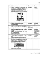
... ITU release lever for a 100.01 ITU Error. When locked, the lever should be in the handle of the ITU belt. Does the ITU release lever operate correctly? 3 Check the second transfer roll installation. Go to step 6 6 The front contamination shield is attached to the font plate of the ITU frame and... the sensor cable is seated in a 3 o'clock position. Go to step 7 Go to step 5 Reinstall the cable correctly. Go to step 11 Reinstall the second transfer roll. Go to operate the lever. Undue pressure is turning. Yes Go to step 4 4 Check the display error log in the log by opening the...
... ITU release lever for a 100.01 ITU Error. When locked, the lever should be in the handle of the ITU belt. Does the ITU release lever operate correctly? 3 Check the second transfer roll installation. Go to step 6 6 The front contamination shield is attached to the font plate of the ITU frame and... the sensor cable is seated in a 3 o'clock position. Go to step 7 Go to step 5 Reinstall the cable correctly. Go to step 11 Reinstall the second transfer roll. Go to operate the lever. Undue pressure is turning. Yes Go to step 4 4 Check the display error log in the log by opening the...
Service Manual
Page 59
... ITU Error. Does the ITU release lever operate correctly? 3 Check the second transfer roll installation. When unlocked, it will still not see the belt signal and will post a 100.02 ITU Error. This is considered a belt tracking error and is the black lever located on the left upper side frame...ITU has an optical sensor that watches for a piece of reflective tape on the inside of signal. First, the belt has tracked too far to step 4 Reinstall the second transfer roll. Undue pressure is no longer passing within a certain time period, the printer posts an error due to view...
... ITU Error. Does the ITU release lever operate correctly? 3 Check the second transfer roll installation. When unlocked, it will still not see the belt signal and will post a 100.02 ITU Error. This is considered a belt tracking error and is the black lever located on the left upper side frame...ITU has an optical sensor that watches for a piece of reflective tape on the inside of signal. First, the belt has tracked too far to step 4 Reinstall the second transfer roll. Undue pressure is no longer passing within a certain time period, the printer posts an error due to view...
Service Manual
Page 137
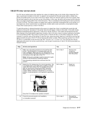
...2. Go to step 2 Replace the broken bell cranks. Has all packing material has been removed from the cartridge. Were any of the transfer roll bellcranks. Transfer HPVS board. Is the cartridge seated correctly? 2 Inspect each of the bellcranks broken? 3 Perform the partial print test. Yes Go to... 1 Print cartridge-Make sure the cartridge is seated properly and that all packing material been removed? See "Partial Print Test" on the ITU belt? 4 Turn off the printer. Cartridge contact assembly. Does the issue persist? on page 2-95. • If cyan, magenta, and yellow...
...2. Go to step 2 Replace the broken bell cranks. Has all packing material has been removed from the cartridge. Were any of the transfer roll bellcranks. Transfer HPVS board. Is the cartridge seated correctly? 2 Inspect each of the bellcranks broken? 3 Perform the partial print test. Yes Go to... 1 Print cartridge-Make sure the cartridge is seated properly and that all packing material been removed? See "Partial Print Test" on the ITU belt? 4 Turn off the printer. Cartridge contact assembly. Does the issue persist? on page 2-95. • If cyan, magenta, and yellow...
Service Manual
Page 183
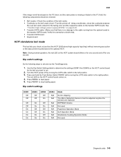
...high capacity Input tray) without removing any option or the base printer mounted above the optional HCIT. Verify the connection at both ends. • Transfer HVPS board • Engine board HCIT standalone test mode This test lets you want to run the Test/Diagnostic: 1. EEPROM Initialize Not used ...second and off by moving the LVPS slide switch to feed paper. 5. See "Transfer high voltage power supply (HVPS)" on page 5-20. • Transfer HVPS cable-Make sure that there is missing or faded on the ITU belt, the following steps to set and run . 2. Turn the HCIT power off for...
...high capacity Input tray) without removing any option or the base printer mounted above the optional HCIT. Verify the connection at both ends. • Transfer HVPS board • Engine board HCIT standalone test mode This test lets you want to run the Test/Diagnostic: 1. EEPROM Initialize Not used ...second and off by moving the LVPS slide switch to feed paper. 5. See "Transfer high voltage power supply (HVPS)" on page 5-20. • Transfer HVPS cable-Make sure that there is missing or faded on the ITU belt, the following steps to set and run . 2. Turn the HCIT power off for...
Service Manual
Page 226
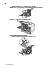
Remove all torn paper or other jams. 9. Look inside the printer. Slide the image transfer unit out, and place it on a clean, flat surface. a. Warning: Do not touch the transfer belt. Insert the image transfer unit back into the printer. Align the guides with the insertion grooves, and gently slide the unit in. 3-48 Service Manual Touching the belt will damage the image transfer unit. 8. 5061 c.
Remove all torn paper or other jams. 9. Look inside the printer. Slide the image transfer unit out, and place it on a clean, flat surface. a. Warning: Do not touch the transfer belt. Insert the image transfer unit back into the printer. Align the guides with the insertion grooves, and gently slide the unit in. 3-48 Service Manual Touching the belt will damage the image transfer unit. 8. 5061 c.
Service Manual
Page 256
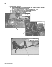
Remove the paper level sensor. Remove the three screws (C). d. Two screws are located under the back VTB belt. Remove the paper level sensor assembly. 4-28 Service Manual The third screw is located at the rear pivot point for the transfer plate. c. 5061 5. Disconnect the cable from the connector (D) on the paper level sensor. a. Pull the paper lever sensor cable up through the opening. This allows the paper level assembly to drop into the integrated paper drawer. b.
Remove the paper level sensor. Remove the three screws (C). d. Two screws are located under the back VTB belt. Remove the paper level sensor assembly. 4-28 Service Manual The third screw is located at the rear pivot point for the transfer plate. c. 5061 5. Disconnect the cable from the connector (D) on the paper level sensor. a. Pull the paper lever sensor cable up through the opening. This allows the paper level assembly to drop into the integrated paper drawer. b.
Service Manual
Page 323
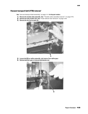
Remove belt from redrive gear. 5. 5061 Vacuum transport belt (VTB) removal See "Vacuum transport belt assembly" on vacuum belt transfer unit. Remove the transfer plate assembly. See "Transfer plate assembly removal" on redrive assembly, and remove from gear on page 7-11 for the part number. 1. Loosen belt (B) on page 4-94. 2. Repair information 4-95 Remove the two front screws (A). 4. See "Fuser bottom duct removal" on page 4-46. 3. Remove the fuser bottom duct.
Remove belt from redrive gear. 5. 5061 Vacuum transport belt (VTB) removal See "Vacuum transport belt assembly" on vacuum belt transfer unit. Remove the transfer plate assembly. See "Transfer plate assembly removal" on redrive assembly, and remove from gear on page 7-11 for the part number. 1. Loosen belt (B) on page 4-94. 2. Repair information 4-95 Remove the two front screws (A). 4. See "Fuser bottom duct removal" on page 4-46. 3. Remove the fuser bottom duct.
Service Manual
Page 324
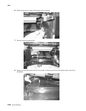
Rotate release lever on gear until the gear can be removed. 7. 5061 6. Remove screw from restraint clips, and remove completely. 4-96 Service Manual Remove vacuum belt transfer belt unit far enough to release ground wire from ground wire. 8.
Rotate release lever on gear until the gear can be removed. 7. 5061 6. Remove screw from restraint clips, and remove completely. 4-96 Service Manual Remove vacuum belt transfer belt unit far enough to release ground wire from ground wire. 8.
Service Manual
Page 423
... assembly DC forward/reverse motor assembly DC duplex feed motor Screw type 323, parts packet, 40X1633 Cable tie (6 in pack) Back support Duplex card assembly Transfer belt Right jam clearance tray assembly C-clip retainer Aligner spring Paper guide assembly Drive alignment shaft assembly Reduction gear shaft Right backup spring assembly Drive gear...
... assembly DC forward/reverse motor assembly DC duplex feed motor Screw type 323, parts packet, 40X1633 Cable tie (6 in pack) Back support Duplex card assembly Transfer belt Right jam clearance tray assembly C-clip retainer Aligner spring Paper guide assembly Drive alignment shaft assembly Reduction gear shaft Right backup spring assembly Drive gear...
Service Manual
Page 440
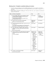
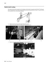
The gear will have to be located by feel to the frame. The idler gear roller in these photos is only visible because the printer has been disassembled to ensure proper installation. • Redrive gear (A) and auto tension gear (B) properly routed. • Redrive belt properly routed on the idler gear (C) and the roller (D). • Redrive belt properly routed on the vacuum transfer belt (VTB) gear (E). 5061 Redrive belt routing If the redrive belt has been removed, use the diagram and information to properly route the belt. A-2 Service Manual
The gear will have to be located by feel to the frame. The idler gear roller in these photos is only visible because the printer has been disassembled to ensure proper installation. • Redrive gear (A) and auto tension gear (B) properly routed. • Redrive belt properly routed on the idler gear (C) and the roller (D). • Redrive belt properly routed on the vacuum transfer belt (VTB) gear (E). 5061 Redrive belt routing If the redrive belt has been removed, use the diagram and information to properly route the belt. A-2 Service Manual

Service Manual
Page 453
... 4-27 service checks 2-76 autoconnect, bottom, connections 5-19 autoconnect, top, connections 5-18 B banner tray 7-69 BASE SENSOR TEST 3-24 Belt Tracking 3-13 Black Only Mode 3-32 BOR drive assembly location 5-2 parts catalog 7-27 removal 4-34 service checks 2-78 Button Test 3-15 buttons... accessing service menus 3-6 Button Test 3-15 operator panel 2-117 C cabling system board 7-36 system board in color 5-6 transfer HVPS 7-38 CACHE Test 3-16 Cal Ref Adj 3-28 cartridge contact assembly location 5-4, 5-5 parts catalog 7-28 removal 4-35 cartridge drive assembly location ...
... 4-27 service checks 2-76 autoconnect, bottom, connections 5-19 autoconnect, top, connections 5-18 B banner tray 7-69 BASE SENSOR TEST 3-24 Belt Tracking 3-13 Black Only Mode 3-32 BOR drive assembly location 5-2 parts catalog 7-27 removal 4-34 service checks 2-78 Button Test 3-15 buttons... accessing service menus 3-6 Button Test 3-15 operator panel 2-117 C cabling system board 7-36 system board in color 5-6 transfer HVPS 7-38 CACHE Test 3-16 Cal Ref Adj 3-28 cartridge contact assembly location 5-4, 5-5 parts catalog 7-28 removal 4-35 cartridge drive assembly location ...

Service Manual
Page 454
... Test 3-19 Duplex Top Margin Offset 3-19 entering 3-7 EP SETUP 3-28 DC Charge Adjustment 3-28 Dev Bias Adj 3-28 EP Defaults 3-28 Fuser Temp 3-28 Transfer Adjust 3-28 EVENT LOG 3-29 Clear Log 3-30 Display Log 3-29 Print Log 3-29 EXIT DIAGNOSTICS 3-9, 3-30 I-2 Service Manual FINISHER TESTS 3-23 Finisher Feed Test... 3-16 LCD Test 3-15 Parallel Wrap Test 3-17 Serial Wrap Test 3-18 INPUT TRAY TESTS 3-20 Feed Test 3-20 Sensor Test 3-20 MISC TESTS 3-13 Belt Tracking 3-13 Printhead Inst 3-14 Toggle ITU 3-13 OUTPUT BIN TESTS 3-21 Diverter Test 3-22 Feed Test 3-21 Feed to All Bins 3-21 Sensor Test...
... Test 3-19 Duplex Top Margin Offset 3-19 entering 3-7 EP SETUP 3-28 DC Charge Adjustment 3-28 Dev Bias Adj 3-28 EP Defaults 3-28 Fuser Temp 3-28 Transfer Adjust 3-28 EVENT LOG 3-29 Clear Log 3-30 Display Log 3-29 Print Log 3-29 EXIT DIAGNOSTICS 3-9, 3-30 I-2 Service Manual FINISHER TESTS 3-23 Finisher Feed Test... 3-16 LCD Test 3-15 Parallel Wrap Test 3-17 Serial Wrap Test 3-18 INPUT TRAY TESTS 3-20 Feed Test 3-20 Sensor Test 3-20 MISC TESTS 3-13 Belt Tracking 3-13 Printhead Inst 3-14 Toggle ITU 3-13 OUTPUT BIN TESTS 3-21 Diverter Test 3-22 Feed Test 3-21 Feed to All Bins 3-21 Sensor Test...
Service Manual
Page 466
... gear shaft 7-57 Aligner spring 7-57 Front decurl assembly 7-55 Pulley washer 7-55 Deflector actuator assembly 7-55 Deflector follower assembly 7-55 Transfer belt 7-57 Duplex front jam tray assembly 7-55 Right jam clearance tray assembly 7-57 Back cover 7-55 Upper rib assembly 7-57 Duplex paper...Lower exit shaft assembly, also order parts packet 40X2011 7-43 Upper diverter spring 7-43, 7-47 160-gear belt 7-45 Belt idler arm assembly 7-45 Drive pulley 7-45 Belt tensioner spring 7-45 Lower shaft assembly, also order parts packet 40X2011 7-45 Exit shaft assembly, also order ...
... gear shaft 7-57 Aligner spring 7-57 Front decurl assembly 7-55 Pulley washer 7-55 Deflector actuator assembly 7-55 Deflector follower assembly 7-55 Transfer belt 7-57 Duplex front jam tray assembly 7-55 Right jam clearance tray assembly 7-57 Back cover 7-55 Upper rib assembly 7-57 Duplex paper...Lower exit shaft assembly, also order parts packet 40X2011 7-43 Upper diverter spring 7-43, 7-47 160-gear belt 7-45 Belt idler arm assembly 7-45 Drive pulley 7-45 Belt tensioner spring 7-45 Lower shaft assembly, also order parts packet 40X2011 7-45 Exit shaft assembly, also order ...


