
User's Guide
Page 107
..., restrictions, liens, and encumbrances. Warranty service does not include repair of the warranty period. Lexington, KY This limited warranty applies to present the feature or option with Lexmark user's guides, manuals, instructions or guidance Unsuitable physical or operating environment Maintenance by anyone.... You may be required to the United States and Canada. Limitation of Limited Warranty C770, C772 printer Lexmark International, Inc. Before you may be available for the remainder of failures caused by Lexmark). Notices Statement of liability Notices 107
..., restrictions, liens, and encumbrances. Warranty service does not include repair of the warranty period. Lexington, KY This limited warranty applies to present the feature or option with Lexmark user's guides, manuals, instructions or guidance Unsuitable physical or operating environment Maintenance by anyone.... You may be required to the United States and Canada. Limitation of Limited Warranty C770, C772 printer Lexmark International, Inc. Before you may be available for the remainder of failures caused by Lexmark). Notices Statement of liability Notices 107

Service Manual
Page 20
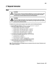
... are several types of the product where you begin, or use caution if the product must receive power in order to repair it. General information contains a general description of the printer and the maintenance approach used to isolate failing field replaceable units ...maintenance contains the lubrication specifications and recommendations to identify the connector locations and test points on the printer. 6. 5061 Preface This manual contains maintenance procedures for making printer adjustments and removing and installing FRUs. 5. Special tools and test equipment, as well as ...
... are several types of the product where you begin, or use caution if the product must receive power in order to repair it. General information contains a general description of the printer and the maintenance approach used to isolate failing field replaceable units ...maintenance contains the lubrication specifications and recommendations to identify the connector locations and test points on the printer. 6. 5061 Preface This manual contains maintenance procedures for making printer adjustments and removing and installing FRUs. 5. Special tools and test equipment, as well as ...
Service Manual
Page 43
... option" on page 2-7 - "1xx service errors" on page 2-5 - "User attendance messages" on page 2-5 - Contact your fingers are not contained in this service manual. 5061 2. Check the "POR (Power-On Reset) sequence" on page 2-5 • If you have an error message or user message, check the following information: ... action necessary to the printer. Disconnect any cable or electronic board or assembly for personal safety and to prevent damage to repair a printer, look for assistance. Diagnostic information 2-1 Make sure your next level of support for the following : -
... option" on page 2-7 - "1xx service errors" on page 2-5 - "User attendance messages" on page 2-5 - Contact your fingers are not contained in this service manual. 5061 2. Check the "POR (Power-On Reset) sequence" on page 2-5 • If you have an error message or user message, check the following information: ... action necessary to the printer. Disconnect any cable or electronic board or assembly for personal safety and to prevent damage to repair a printer, look for assistance. Diagnostic information 2-1 Make sure your next level of support for the following : -
Service Manual
Page 78
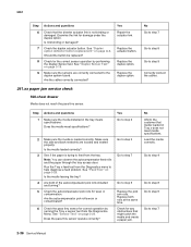
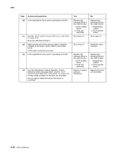
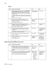
Examine the link for correct operation by performing the Duplex Sensor test. Should the button be replaced? Yes Repair the actuator link. Are the autocompensator pick rolls worn or contaminated? 6 Check the pass thru sensor for damage under the duplex option....the pass thru sensor operate correctly? 5061 Step 6 7 8 9 Actions and questions Check that the diverter actuator link is trying to step 7 2-36 Service Manual Step 1 Actions and questions Make sure the media installed in Tray x does not meet specifications? 2 Make sure the media is loaded correctly. See "Feed ...
Examine the link for correct operation by performing the Duplex Sensor test. Should the button be replaced? Yes Repair the actuator link. Are the autocompensator pick rolls worn or contaminated? 6 Check the pass thru sensor for damage under the duplex option....the pass thru sensor operate correctly? 5061 Step 6 7 8 9 Actions and questions Check that the diverter actuator link is trying to step 7 2-36 Service Manual Step 1 Actions and questions Make sure the media installed in Tray x does not meet specifications? 2 Make sure the media is loaded correctly. See "Feed ...
Service Manual
Page 82
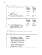
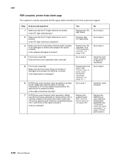
...used in the feed unit assembly. No Replace the following FRUs in the order shown: 1. Registration sensor. 2. HCIT system board. Feed unit assembly. Repair or replace parts as possible to stick together in the tray. • No cotton content, or as little as necessary. Go to step 2 2-...40 Service Manual Rough or ridged surfaces may cause the envelopes to meet specifications. Are you able to the paper path. • Smooth surface on the envelopes...
...used in the feed unit assembly. No Replace the following FRUs in the order shown: 1. Registration sensor. 2. HCIT system board. Feed unit assembly. Repair or replace parts as possible to stick together in the tray. • No cotton content, or as little as necessary. Go to step 2 2-...40 Service Manual Rough or ridged surfaces may cause the envelopes to meet specifications. Are you able to the paper path. • Smooth surface on the envelopes...
Service Manual
Page 86
... the order shown: 1. HCIT system board. 2. HCIT system board. 2. No Replace the following FRUs in the order shown: 1. Replace the feed unit assembly. 2-44 Service Manual Repair or replace parts as necessary. Does the LED flash 8 times? 12 Make sure the pick home sensor cable is occurring? HCIT system board.
... the order shown: 1. HCIT system board. 2. HCIT system board. 2. No Replace the following FRUs in the order shown: 1. Replace the feed unit assembly. 2-44 Service Manual Repair or replace parts as necessary. Does the LED flash 8 times? 12 Make sure the pick home sensor cable is occurring? HCIT system board.
Service Manual
Page 92
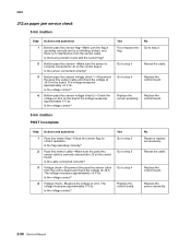
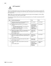
...the sensor is correctly connected to J3 on the control board. The voltage measures approximately +5 V dc. Is the voltage correct? Is the voltage correct? No Repair or replace as necessary. Is the voltage correct? Voltage check-Measure the voltage at J5-2 on the control board. 5061 272.xx paper jam service... step 2 Reseat the cable. Yes Go to step 2 Go to step 3 Go to step 4 Replace the control board. Replace the sensor assembly. 2-50 Service Manual Bottom pass thru sensor voltage check 2-Check the voltage at J3-2. Is there any problem found with the sensor flag?
...the sensor is correctly connected to J3 on the control board. The voltage measures approximately +5 V dc. Is the voltage correct? Is the voltage correct? No Repair or replace as necessary. Is the voltage correct? Voltage check-Measure the voltage at J5-2 on the control board. 5061 272.xx paper jam service... step 2 Reseat the cable. Yes Go to step 2 Go to step 3 Go to step 4 Replace the control board. Replace the sensor assembly. 2-50 Service Manual Bottom pass thru sensor voltage check 2-Check the voltage at J3-2. Is there any problem found with the sensor flag?
Service Manual
Page 112
... parts for any signs of wear, broken gear teeth, or damaged parts. Yes Replace parts or repairs necessary. No Go to step 2 Go to step 3 Replace bin x solenoid assembly. No Repair or replace as necessary. Bin x solenoid-Check the resistance of the solenoid. Replace the 5-Bin Mailbox...Actions and questions Bin x sensor flag-Make sure the bin x sensor flag is operating correctly. Replace the 5-Bin Mailbox control board assembly. 2-70 Service Manual Yes Replace the bin x sensor. 5061 Ready-bin x full displays and paper feeds into the bin selected. 272.xx Paper Jam-check bin 1 ...
... parts for any signs of wear, broken gear teeth, or damaged parts. Yes Replace parts or repairs necessary. No Go to step 2 Go to step 3 Replace bin x solenoid assembly. No Repair or replace as necessary. Bin x solenoid-Check the resistance of the solenoid. Replace the 5-Bin Mailbox...Actions and questions Bin x sensor flag-Make sure the bin x sensor flag is operating correctly. Replace the 5-Bin Mailbox control board assembly. 2-70 Service Manual Yes Replace the bin x sensor. 5061 Ready-bin x full displays and paper feeds into the bin selected. 272.xx Paper Jam-check bin 1 ...
Service Manual
Page 114
... pick arm lift bellcrank installed correctly? Go to step 3 2 Check the cable connection for the paper low/out sensor to step 4 Repair or replace as necessary. Check the following for correct Go to step 3 Install the bellcrank correctly. Install the paper level sensing assembly correctly... following for sensor L2? Step Actions and questions Yes 1 Run Tray x sensor test from the Diagnostics Menu. Remove the tray, and manually reset the autocompensator to its down position. Contact your next level of these parts loose, broken, or missing? Is the paper level sensing...
... pick arm lift bellcrank installed correctly? Go to step 3 2 Check the cable connection for the paper low/out sensor to step 4 Repair or replace as necessary. Check the following for correct Go to step 3 Install the bellcrank correctly. Install the paper level sensing assembly correctly... following for sensor L2? Step Actions and questions Yes 1 Run Tray x sensor test from the Diagnostics Menu. Remove the tray, and manually reset the autocompensator to its down position. Contact your next level of these parts loose, broken, or missing? Is the paper level sensing...
Service Manual
Page 120
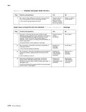
... 1 is a dual sensor and checks the following order: 1. Is there continuity? Yes Contact your next level of the paper level sensing cable. Repair or replace parts as necessary. Remove the print cartridges, and watch the belt while activating the toggle function. "System board removal" on page 4-34...properly? Do the cams move up and down when the ITU is preventing the proper movement. 2-78 Service Manual Install correctly or replace the flag if damaged or broken. Locate the BOR gear, and manually activate the gear. 5061 Step D Step 1 2 3 4 5 6 Actions and questions Enter the ...
... 1 is a dual sensor and checks the following order: 1. Is there continuity? Yes Contact your next level of the paper level sensing cable. Repair or replace parts as necessary. Remove the print cartridges, and watch the belt while activating the toggle function. "System board removal" on page 4-34...properly? Do the cams move up and down when the ITU is preventing the proper movement. 2-78 Service Manual Install correctly or replace the flag if damaged or broken. Locate the BOR gear, and manually activate the gear. 5061 Step D Step 1 2 3 4 5 6 Actions and questions Enter the ...
Service Manual
Page 122
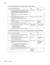
..., printer feeds blank page This symptom is not broken or damaged and actuates the switches correctly. Go to step 4 Install the front cover correctly, or repair as necessary. See "Front cover or front cover backplate assembly removal" on the system board. Is the actuator damaged or broken? 4 Front cover assembly Does... that the cable is correctly connected to system board-Make sure that the ITU light shield is seated correctly. Check for part number.) 2-80 Service Manual See "System board removal" on page 4-49. Yes Replace the ITU light shield.
..., printer feeds blank page This symptom is not broken or damaged and actuates the switches correctly. Go to step 4 Install the front cover correctly, or repair as necessary. See "Front cover or front cover backplate assembly removal" on the system board. Is the actuator damaged or broken? 4 Front cover assembly Does... that the cable is correctly connected to system board-Make sure that the ITU light shield is seated correctly. Check for part number.) 2-80 Service Manual See "System board removal" on page 4-49. Yes Replace the ITU light shield.
Service Manual
Page 128
... the front and side doors. Is the voltage correct? Check the AC line voltage at CN2 pin 2 on the HCIT? Yes Go to the LVPS. Repair as necessary. Step 1 2 3 4 5 6 Actions and questions Does the printer power up and work normally when plugged into the AC voltage source. The voltage should ...Is the voltage correct? Replace the HCIT system board. Determine where the AC line voltage is being lost to step 6 Replace the cables. 2-86 Service Manual Is the LED on solid or blinking? • On solid means that the HCIT has detected the front door or side door open. • Blinking...
... the front and side doors. Is the voltage correct? Check the AC line voltage at CN2 pin 2 on the HCIT? Yes Go to the LVPS. Repair as necessary. Step 1 2 3 4 5 6 Actions and questions Does the printer power up and work normally when plugged into the AC voltage source. The voltage should ...Is the voltage correct? Replace the HCIT system board. Determine where the AC line voltage is being lost to step 6 Replace the cables. 2-86 Service Manual Is the LED on solid or blinking? • On solid means that the HCIT has detected the front door or side door open. • Blinking...
Service Manual
Page 152
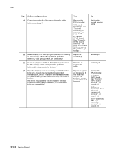
..." on page 4-91. See "Transfer HVPS board removal" on page 4-88. 2) Transfer HPVS board. Repair as necessary. Yes Replace the FRUs in order: 1) Transfer HVPS board. Repair or replace as necessary. 5061 Step 4 Actions and questions Check the continuity of support. If this does ...assemblies to step 7 Replace the FRUs in order: 1) Second transfer roll. See "Second transfer roll removal" on page 4-49. 2-110 Service Manual See "Transfer HVPS board removal" on page 4-91. 2) Second transfer roll. Are there any problems with the transfer terminal contact, transfer cable...
..." on page 4-91. See "Transfer HVPS board removal" on page 4-88. 2) Transfer HPVS board. Repair as necessary. Yes Replace the FRUs in order: 1) Transfer HVPS board. Repair or replace as necessary. 5061 Step 4 Actions and questions Check the continuity of support. If this does ...assemblies to step 7 Replace the FRUs in order: 1) Second transfer roll. See "Second transfer roll removal" on page 4-49. 2-110 Service Manual See "Transfer HVPS board removal" on page 4-91. 2) Second transfer roll. Are there any problems with the transfer terminal contact, transfer cable...

