
Service Manual
Page 6
Side Frame / Covers 7-28 Assembly 8:Tractor 2 Option 7-30 viii Service Manual Parts Catalog 7-1 How To Use This Parts Catalog 7-1 Assembly 1: Major Components 7-2 Assembly 2: Covers 7-6 Assembly 3: Carrier 7-10 Assembly 4: Paper Guide / Platen / Feed Roller 7-16 Assembly 5: Electronics 7-20 Assembly 6: ASF - Roller / Support 7-26 Assembly 7: ASF -
Side Frame / Covers 7-28 Assembly 8:Tractor 2 Option 7-30 viii Service Manual Parts Catalog 7-1 How To Use This Parts Catalog 7-1 Assembly 1: Major Components 7-2 Assembly 2: Covers 7-6 Assembly 3: Carrier 7-10 Assembly 4: Paper Guide / Platen / Feed Roller 7-16 Assembly 5: Electronics 7-20 Assembly 6: ASF - Roller / Support 7-26 Assembly 7: ASF -

Service Manual
Page 13
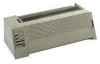
...Lexmark 238X and 239X - The 23XX Forms Printers (23XX-003), in addition to the features of the 23XX-002 printers are enhanced versions of the 2390-001, which has a distinctive PS/1 logo but is also a PS/1 version of the basic 23XX-001 printers. General Information 1-1 They also support... the Tractor 2 Options. There is otherwise identical to the 2390-001. 1. XXX printers are small versatile tabletop printers suitable for applications that use continuous or multipart forms. The ...
...Lexmark 238X and 239X - The 23XX Forms Printers (23XX-003), in addition to the features of the 23XX-002 printers are enhanced versions of the 2390-001, which has a distinctive PS/1 logo but is also a PS/1 version of the basic 23XX-001 printers. General Information 1-1 They also support... the Tractor 2 Options. There is otherwise identical to the 2390-001. 1. XXX printers are small versatile tabletop printers suitable for applications that use continuous or multipart forms. The ...

Service Manual
Page 16
Options The following options may be installed on 238X/239X printers: • Auto Sheet Feeder (ASF) • 32Kb Memory Module, Volatile • 32Kb Memory Module, Non-volatile • Serial Interface Attachment (RS232/RS422). • Extended National Language Support modules (World Trade only) • Acoustics Option • Extended Cut-sheet Paper Guides • Tractor...
Options The following options may be installed on 238X/239X printers: • Auto Sheet Feeder (ASF) • 32Kb Memory Module, Volatile • 32Kb Memory Module, Non-volatile • Serial Interface Attachment (RS232/RS422). • Extended National Language Support modules (World Trade only) • Acoustics Option • Extended Cut-sheet Paper Guides • Tractor...

Service Manual
Page 19
...settings are for "Snap-On". • 23XX-002: • In-line gray box with all printers. • Some adapters may be installed on printers other than what is listed. • Only the "Black" adapter is turned off and then on...002, but different switch definitions. • All units have a power lead. • Switch settings are valid only after printer power is available as noted, all adapters work with a short cable to the parallel port. • Some units have... V port. • Units without the power cord will not work on again. • Contact Lexmark Technical Support for "Black".
...settings are for "Snap-On". • 23XX-002: • In-line gray box with all printers. • Some adapters may be installed on printers other than what is listed. • Only the "Black" adapter is turned off and then on...002, but different switch definitions. • All units have a power lead. • Switch settings are valid only after printer power is available as noted, all adapters work with a short cable to the parallel port. • Some units have... V port. • Units without the power cord will not work on again. • Contact Lexmark Technical Support for "Black".

Service Manual
Page 83
Remove the left roller bushing [1] as shown. 4. Move the pick-up gear see "Auto Sheet Feeder Gears Removal" on page 4-8. 3. Remove the right roller bushing [2]. 5. Remove the idler gear and pick-up roller [3] to both ends of the shaft, and then remove them. Repair Information 4-9 Remove the covers and the cut sheet support. 2. Auto Sheet Feeder Pick-up Roller Removal 1.
Remove the left roller bushing [1] as shown. 4. Move the pick-up gear see "Auto Sheet Feeder Gears Removal" on page 4-8. 3. Remove the right roller bushing [2]. 5. Remove the idler gear and pick-up roller [3] to both ends of the shaft, and then remove them. Repair Information 4-9 Remove the covers and the cut sheet support. 2. Auto Sheet Feeder Pick-up Roller Removal 1.

Service Manual
Page 84
... plate [2] to the bottom cover. Release the two latches [1] then remove the power supply ground plate [4] by sliding it toward you. 8. Remove the rubber board support [5]. 7. 2380 & 2390 - Remove the top cover see "Power Supply Removal" on page 4-46. 5. Remove the power supply unit see "Top Cover Removal" on page 4-53...
... plate [2] to the bottom cover. Release the two latches [1] then remove the power supply ground plate [4] by sliding it toward you. 8. Remove the rubber board support [5]. 7. 2380 & 2390 - Remove the top cover see "Power Supply Removal" on page 4-46. 5. Remove the power supply unit see "Top Cover Removal" on page 4-53...

Service Manual
Page 92
... carrier see "Paper Guide / Platen Assembly Removal" on page 4-12. 11. 23XX-002, 003: Remove the tractor idler gear. 12. 23XX-002, 003: Remove the support plate. 13. Remove the home position sensor see "Paper Select Lever Removal" on page 4-25. 17. Carrier Plate Removal 1. Remove the paper select lever see...
... carrier see "Paper Guide / Platen Assembly Removal" on page 4-12. 11. 23XX-002, 003: Remove the tractor idler gear. 12. 23XX-002, 003: Remove the support plate. 13. Remove the home position sensor see "Paper Select Lever Removal" on page 4-25. 17. Carrier Plate Removal 1. Remove the paper select lever see...

Service Manual
Page 95
Download or Print Buffer Module Removal Notes: • Turn the printer Off and disconnect the power cord at the printer. • The Download Module and the Print Buffer Module are options. 1. Repair Information 4-21 Remove the rear cover. 2. Insert a small flat screwdriver [1] under each end of the module and lift up gently. (On 23XX-002, 003 printers only one end of the module is accessible.) Do not insert the screwdriver too deep, or the main logic board may be damaged. Note: Be careful not to bend the pins when you re-install the module. Remove the paper support. 3.
Download or Print Buffer Module Removal Notes: • Turn the printer Off and disconnect the power cord at the printer. • The Download Module and the Print Buffer Module are options. 1. Repair Information 4-21 Remove the rear cover. 2. Insert a small flat screwdriver [1] under each end of the module and lift up gently. (On 23XX-002, 003 printers only one end of the module is accessible.) Do not insert the screwdriver too deep, or the main logic board may be damaged. Note: Be careful not to bend the pins when you re-install the module. Remove the paper support. 3.

Service Manual
Page 99
Remove the top cover see "Top Cover Removal" on newer models. Disconnect the home position sensor cable from the left side support plate on page 4-61. 2. Repair Information 4-25 The sensor is attached to the left side frame. Remove the screw [1], and then remove the home position sensor from the sub logic board. 3. Home Position Sensor Removal 1.
Remove the top cover see "Top Cover Removal" on newer models. Disconnect the home position sensor cable from the left side support plate on page 4-61. 2. Repair Information 4-25 The sensor is attached to the left side frame. Remove the screw [1], and then remove the home position sensor from the sub logic board. 3. Home Position Sensor Removal 1.

Service Manual
Page 102
...feed roller see "Upper Feed Roller Removal" on page 4-32. 11. Remove the screw [8] that was covered by the gear and remove the metal support plate. Remove the lower pinch roller see "Head Gap Sensor Removal (238X-001)" on page 4-12. 9. Remove the head gap sensor see "...238X-001 - Remove the pull tractor sensor see "Carrier Motor Assembly Removal" on page 4-59. 6. Remove the large idler gear [7] by the support plate. 23XX-001 printers have only one screw to remove. 17. 238X-XXX - Remove the platen bar screw [8] that was covered by inserting a small blade screwdriver ...
...feed roller see "Upper Feed Roller Removal" on page 4-32. 11. Remove the screw [8] that was covered by the gear and remove the metal support plate. Remove the lower pinch roller see "Head Gap Sensor Removal (238X-001)" on page 4-12. 9. Remove the head gap sensor see "...238X-001 - Remove the pull tractor sensor see "Carrier Motor Assembly Removal" on page 4-59. 6. Remove the large idler gear [7] by the support plate. 23XX-001 printers have only one screw to remove. 17. 238X-XXX - Remove the platen bar screw [8] that was covered by inserting a small blade screwdriver ...

Service Manual
Page 114
...Removal" on page 4-59. 7. Remove the paper feed motor see "Upper Feed Roller Removal" on page 4-38. 8. Remove the metal support plate mounting screw and the support plate. Remove the upper feed roller see "Paper Feed Motor Removal" on page 4-66. 12. Remove the platen bar screw that was ...see "Lower Feed Roller Removal" on page 4-48. 6. Remove the top cover see "Right Side Frame Removal" on page 4-61. 3. Remove the rear support plate mounting screw that was covered by the gear. Remove the right side frame see "Top Cover Removal" on page 4-56. 16. Remove the tractor...
...Removal" on page 4-59. 7. Remove the paper feed motor see "Upper Feed Roller Removal" on page 4-38. 8. Remove the metal support plate mounting screw and the support plate. Remove the upper feed roller see "Paper Feed Motor Removal" on page 4-66. 12. Remove the platen bar screw that was ...see "Lower Feed Roller Removal" on page 4-48. 6. Remove the top cover see "Right Side Frame Removal" on page 4-61. 3. Remove the rear support plate mounting screw that was covered by the gear. Remove the right side frame see "Top Cover Removal" on page 4-56. 16. Remove the tractor...

Service Manual
Page 120
... ground leg [5] goes on page 4-61. 3. Power Supply Removal CAUTION: The power supply may be hot. 1. Remove the power supply. Turn off the printer and disconnect the power cord at both ends. 2. Disconnect the power supply cable [3]. 5. Remove the four mounting screws [4]. 6. The ground spring on top ...of the power supply goes behind the frame support shaft and in front of the power supply cover. Do not lose the star washer [2], if present, located between the ground wire and the shield...
... ground leg [5] goes on page 4-61. 3. Power Supply Removal CAUTION: The power supply may be hot. 1. Remove the power supply. Turn off the printer and disconnect the power cord at both ends. 2. Disconnect the power supply cable [3]. 5. Remove the four mounting screws [4]. 6. The ground spring on top ...of the power supply goes behind the frame support shaft and in front of the power supply cover. Do not lose the star washer [2], if present, located between the ground wire and the shield...

Service Manual
Page 130
... the right side frame see "Top Cover Removal" on the carrier belt by loosening the screw and pushing the assembly toward the center of the printer. 7. Remove the feed roll bushings [1] from the right side of the shaft. Remove the paper select lever see "Print Unit Removal" on page 4-42. 4.... [5] holding the right side frame to -power supply ground leg from the right side frame. 14. Remove the ground spring and the platen-to the support shaft [7]. 16. Do not lose the small bushing on page 4-2. 4-56 Release the two latches [6] and remove the right side frame. 18. Rotate the...
... the right side frame see "Top Cover Removal" on the carrier belt by loosening the screw and pushing the assembly toward the center of the printer. 7. Remove the feed roll bushings [1] from the right side of the shaft. Remove the paper select lever see "Print Unit Removal" on page 4-42. 4.... [5] holding the right side frame to -power supply ground leg from the right side frame. 14. Remove the ground spring and the platen-to the support shaft [7]. 16. Do not lose the small bushing on page 4-2. 4-56 Release the two latches [6] and remove the right side frame. 18. Rotate the...

Service Manual
Page 132
... feed roller right gear [4]. 4-58 Release the latch [1] and then remove the ASF drive gear. 4. 23XX-003: Remove the two screws and remove the shaft support plate (not shown). 5. Remove both E rings [2],[3] and then remove the ASF idler gear and the shift gear from springing off, hold them down while removing...
... feed roller right gear [4]. 4-58 Release the latch [1] and then remove the ASF drive gear. 4. 23XX-003: Remove the two screws and remove the shaft support plate (not shown). 5. Remove both E rings [2],[3] and then remove the ASF idler gear and the shift gear from springing off, hold them down while removing...

Service Manual
Page 177
...-003) Side Frame Locking Plates Screw, Washer & Clip Kit (23XX-001) Screw, Washer & Clip Kit (23XX-002) Screw, Washer & Clip Kit (23XX-003) Tractor Paper Support (2381 & 2391) Serial Interface Adapter Parts Catalog 7-5
...-003) Side Frame Locking Plates Screw, Washer & Clip Kit (23XX-001) Screw, Washer & Clip Kit (23XX-002) Screw, Washer & Clip Kit (23XX-003) Tractor Paper Support (2381 & 2391) Serial Interface Adapter Parts Catalog 7-5
Service Manual
Page 185
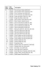
...-001, 23XX-002) Release Slider Cam (23XX-003) Sub Slider Cam (23XX-003) Head Gap Sensor (238X-001) Head Gap Sensor Assembly (23XX-002, 003) Support Plate, left side (23XX-002, 003) Shaft Support Plate (23XX-003) Parts Catalog 7-13
...-001, 23XX-002) Release Slider Cam (23XX-003) Sub Slider Cam (23XX-003) Head Gap Sensor (238X-001) Head Gap Sensor Assembly (23XX-002, 003) Support Plate, left side (23XX-002, 003) Shaft Support Plate (23XX-003) Parts Catalog 7-13
Service Manual
Page 189
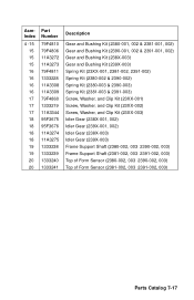
... (23XX-003) Idler Gear (238X-001, 002) Idler Gear (239X-001, 002) Idler Gear (238X-003) Idler Gear (239X-003) Frame Support Shaft (2380-002, 003 2390-002, 003) Frame Support Shaft (2381-002, 003 2391-002, 003) Top of Form Sensor (2380-002, 003 2390-002, 003) Top of Form Sensor...
... (23XX-003) Idler Gear (238X-001, 002) Idler Gear (239X-001, 002) Idler Gear (238X-003) Idler Gear (239X-003) Frame Support Shaft (2380-002, 003 2390-002, 003) Frame Support Shaft (2381-002, 003 2391-002, 003) Top of Form Sensor (2380-002, 003 2390-002, 003) Top of Form Sensor...
Service Manual
Page 197
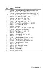
... 95F6881 95F6892 95F6893 95F6894 95F6898 Description Paper Guide(23XX-001,002, 2380-003, 2390-003) Cut Sheet Support (2380 & 2390) Cut Sheet Support (2381-001, 002 & 2391-001,002) Cut Sheet Support W/ Guides (2381-003, 2391-003) Feed Roller Upper (2380 & 2390) Feed Roller Upper (2381... & 2391) Pick-up Roller (L & R) (2381-003, 2391-003) Pick-up Roller (All others) Hopper (R) Paper Support (R) (2381-003, 2391-003) Paper Support (R) (All others) Paper Support (C) (2381 & 2391) Paper Support (L) Hopper (L) (2381-003, 2391-003) Hopper (L) (All others) Paper Load Lever (2381-003, 2391-003) Paper ...
... 95F6881 95F6892 95F6893 95F6894 95F6898 Description Paper Guide(23XX-001,002, 2380-003, 2390-003) Cut Sheet Support (2380 & 2390) Cut Sheet Support (2381-001, 002 & 2391-001,002) Cut Sheet Support W/ Guides (2381-003, 2391-003) Feed Roller Upper (2380 & 2390) Feed Roller Upper (2381... & 2391) Pick-up Roller (L & R) (2381-003, 2391-003) Pick-up Roller (All others) Hopper (R) Paper Support (R) (2381-003, 2391-003) Paper Support (R) (All others) Paper Support (C) (2381 & 2391) Paper Support (L) Hopper (L) (2381-003, 2391-003) Hopper (L) (All others) Paper Load Lever (2381-003, 2391-003) Paper ...

Service Manual
Page 201
AsmIndex 8 -1 1 2 3 3 4 5 5 6 7 8 9 9 10 10 Part Number 11A3342 11A3343 11A3338 11A3339 11A3340 1333160 11A3335 11A3336 11A3337 11A3341 11A3332 95F6902 95F6903 11A3283 11A3284 Description Paper Table W/ Guides, Narrow Paper Table W/ Guides, Wide Tractor Paper Guide Tractor and Frame Asm, Narrow Tractor and Frame Asm, Wide Tractor Kit (L & R) Board Asm W/Cable and Ferrite, Narrow Board Asm W/Cable and Ferrite, Wide Motor Parts Packet Right Cover Front Cover, Narrow Front Cover, Wide Support Shaft, Narrow Support Shaft, Wide Parts Catalog 7-29
AsmIndex 8 -1 1 2 3 3 4 5 5 6 7 8 9 9 10 10 Part Number 11A3342 11A3343 11A3338 11A3339 11A3340 1333160 11A3335 11A3336 11A3337 11A3341 11A3332 95F6902 95F6903 11A3283 11A3284 Description Paper Table W/ Guides, Narrow Paper Table W/ Guides, Wide Tractor Paper Guide Tractor and Frame Asm, Narrow Tractor and Frame Asm, Wide Tractor Kit (L & R) Board Asm W/Cable and Ferrite, Narrow Board Asm W/Cable and Ferrite, Wide Motor Parts Packet Right Cover Front Cover, Narrow Front Cover, Wide Support Shaft, Narrow Support Shaft, Wide Parts Catalog 7-29

Service Manual
Page 203
... Empty Sensor 2-13 Paper Select Sensor 2-13 L Lubrication 6-1 M Models available 1-1 O Operator Errors Irrecoverable 2-13 P Parts Auto Sheet Feeder Covers 7-28 Roller 7-26 Side Frame 7-28 Support 7-26 Carrier 7-10 Covers 7-6, 7-8 Electronics 7-20 Feed Roller 7-16 Paper Guide 7-16 Platen 7-16 Tractor 2 Option 7-30 Parts catalog How to use 7-1 Preventive Maintenance 6-1 Lubrication...
... Empty Sensor 2-13 Paper Select Sensor 2-13 L Lubrication 6-1 M Models available 1-1 O Operator Errors Irrecoverable 2-13 P Parts Auto Sheet Feeder Covers 7-28 Roller 7-26 Side Frame 7-28 Support 7-26 Carrier 7-10 Covers 7-6, 7-8 Electronics 7-20 Feed Roller 7-16 Paper Guide 7-16 Platen 7-16 Tractor 2 Option 7-30 Parts catalog How to use 7-1 Preventive Maintenance 6-1 Lubrication...