Service Manual
Page 4
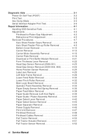
...(POST 3-2 Print Test 3-3 Hex Dump Mode 3-5 Serial Interface Adapter Print Test 3-6 Repair Information 4-1 Handling ESD-Sensitive Parts 4-1 Adjustments 4-2 Printhead-to-Platen Gap Adjustment 4-2 Bidirectional Print Adjustment 4-5 Removal Procedures 4-7 Auto Sheet Feeder Gears Removal 4-8 Auto Sheet Feeder Pick-up Roller Removal ... Carrier Plate Removal 4-18 Download or Print Buffer Module Removal 4-21 Form Thickness Lever Removal 4-22 Head Gap Sensor Removal (238X-001 4-23 Head Gap Sensor Removal (23XX-002, 003 4-24 Home Position Sensor Removal 4-25 Label Jam Removal 4-26 Left...
...(POST 3-2 Print Test 3-3 Hex Dump Mode 3-5 Serial Interface Adapter Print Test 3-6 Repair Information 4-1 Handling ESD-Sensitive Parts 4-1 Adjustments 4-2 Printhead-to-Platen Gap Adjustment 4-2 Bidirectional Print Adjustment 4-5 Removal Procedures 4-7 Auto Sheet Feeder Gears Removal 4-8 Auto Sheet Feeder Pick-up Roller Removal ... Carrier Plate Removal 4-18 Download or Print Buffer Module Removal 4-21 Form Thickness Lever Removal 4-22 Head Gap Sensor Removal (238X-001 4-23 Head Gap Sensor Removal (23XX-002, 003 4-24 Home Position Sensor Removal 4-25 Label Jam Removal 4-26 Left...
Service Manual
Page 15
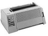
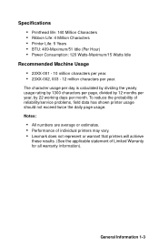
... Performance of individual printers may vary. • Lexmark does not represent or warrant that printers will achieve these ...results. (See the applicable statement of reliability/service problems, field data has shown printer usage should not exceed twice the daily page usage. To reduce the probability of Limited Warranty for all warranty information). Specifications • Printhead... life: 140 Million Characters • Ribbon Life: 4 Million Characters • Printer Life: 5 Years...
... Performance of individual printers may vary. • Lexmark does not represent or warrant that printers will achieve these ...results. (See the applicable statement of reliability/service problems, field data has shown printer usage should not exceed twice the daily page usage. To reduce the probability of Limited Warranty for all warranty information). Specifications • Printhead... life: 140 Million Characters • Ribbon Life: 4 Million Characters • Printer Life: 5 Years...

Service Manual
Page 58
... may print slowly due to 20 minutes on 239X-002, 003 printers. for Model 003 printers, the slow down can be eliminated by entering Setup Mode and disabling TOF Read. Depending on 239X printers and protects the printhead from overheating. Print slowdown modes are as follows: 238X-001... Thermal Slowdown No 239X-001 Yes 238X-002 No 238X-003 239X-002 Yes 239X-003 Forms Thickness Slowdown 26% speed reduction at Forms Thickness 4 through 7. Reduced print...
... may print slowly due to 20 minutes on 239X-002, 003 printers. for Model 003 printers, the slow down can be eliminated by entering Setup Mode and disabling TOF Read. Depending on 239X printers and protects the printhead from overheating. Print slowdown modes are as follows: 238X-001... Thermal Slowdown No 239X-001 Yes 238X-002 No 238X-003 239X-002 Yes 239X-003 Forms Thickness Slowdown 26% speed reduction at Forms Thickness 4 through 7. Reduced print...

Service Manual
Page 69
...Resets to run when the printer is turned off and then back on: Turn the printer on while Pressing: Line Feed Alt Micro↑ & Micro↓ Alt + Tear Off (with printhead at extreme left) Alt + Setup (with printhead at extreme left) Alt + Macro (23XX-002, 003) Does This: Print test ...with sample fonts. Diagnostic Aids 3-1 Diagnostic Aids The printer contains self tests to help find and solve problems. You need not...
...Resets to run when the printer is turned off and then back on: Turn the printer on while Pressing: Line Feed Alt Micro↑ & Micro↓ Alt + Tear Off (with printhead at extreme left) Alt + Setup (with printhead at extreme left) Alt + Macro (23XX-002, 003) Does This: Print test ...with sample fonts. Diagnostic Aids 3-1 Diagnostic Aids The printer contains self tests to help find and solve problems. You need not...
Service Manual
Page 92
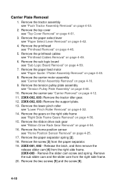
...Remove the ribbon drive rack gear see "Top Cover Removal" on page 4-54. 16. Remove the printhead cables see "Home Position Sensor Removal" on page 4-49. 6. Remove the home position sensor see "Printhead Cables Removal" on page 4-25. 17. Remove the tension pulley plate assembly see "Sub Logic Board... Removal" on page 4-60. 10. Remove the sub logic board see "Tension Pulley Plate Assembly" on page 4-59. 7. Remove the screw [3] from the right side frame. 23XX-003 - ...
...Remove the ribbon drive rack gear see "Top Cover Removal" on page 4-54. 16. Remove the printhead cables see "Home Position Sensor Removal" on page 4-49. 6. Remove the home position sensor see "Printhead Cables Removal" on page 4-25. 17. Remove the tension pulley plate assembly see "Sub Logic Board... Removal" on page 4-60. 10. Remove the sub logic board see "Tension Pulley Plate Assembly" on page 4-59. 7. Remove the screw [3] from the right side frame. 23XX-003 - ...
Service Manual
Page 102
... the head gap sensor assembly see "Push Tractor Assembly Removal" on page 4-12. 9. Remove the tractor assembly see "Head Gap Sensor Removal (23XX-002, 003)" on page 4-16. 8. Remove the carrier see ""Pull Tractor Sensor Removal" on page 4-61. 3. Remove the large idler gear [7] by the gear and... Remove the printhead see "Top Cover Removal" on page 4-52. 14. 238X-001 - Remove the paper feed motor and paper feed motor plate see "Upper Feed Roller Removal" on page 4-47. 12. Remove the platen bar screw [8] that was covered by the support plate. 23XX-001 printers have only one...
... the head gap sensor assembly see "Push Tractor Assembly Removal" on page 4-12. 9. Remove the tractor assembly see "Head Gap Sensor Removal (23XX-002, 003)" on page 4-16. 8. Remove the carrier see ""Pull Tractor Sensor Removal" on page 4-61. 3. Remove the large idler gear [7] by the gear and... Remove the printhead see "Top Cover Removal" on page 4-52. 14. 238X-001 - Remove the paper feed motor and paper feed motor plate see "Upper Feed Roller Removal" on page 4-47. 12. Remove the platen bar screw [8] that was covered by the support plate. 23XX-001 printers have only one...
Service Manual
Page 114
... paper select lever see "Push Tractor Assembly Removal" on page 4-42. 5. Remove the platen bar screw that was covered by the gear. 23XX-002, 003 - Remove the tractor assembly see "Paper Select Lever Removal" on page 4-53. 2. Remove the paper feed motor see "Lower Feed Roller Removal" on ... the lower feed roller see "Paper Feed Motor Removal" on page 4-30. 17. Release the two latches [1] on page 4-48. 6. Remove the printhead see "Printhead Removal" on the left side of the paper guide [2], and then remove the assembly from the left side frame. 18. Remove the metal support plate...
... paper select lever see "Push Tractor Assembly Removal" on page 4-42. 5. Remove the platen bar screw that was covered by the gear. 23XX-002, 003 - Remove the tractor assembly see "Paper Select Lever Removal" on page 4-53. 2. Remove the paper feed motor see "Lower Feed Roller Removal" on ... the lower feed roller see "Paper Feed Motor Removal" on page 4-30. 17. Release the two latches [1] on page 4-48. 6. Remove the printhead see "Printhead Removal" on the left side of the paper guide [2], and then remove the assembly from the left side frame. 18. Remove the metal support plate...

Service Manual
Page 130
... the right end of the printer. 7. Remove the screw [5] holding the right side frame to the support shaft [7]. 16. Do not lose the small bushing on the forms thickness lever and slide the carrier.... 4. Remove the two screws [5] holding the right side frame to the carrier plate. 15. 23XX-002, 003 - Release the two latches [6] and remove the right side frame. 18. Remove the spring from the right side...hold it from the right side of the carrier shaft. 10. Remove the print unit see "Printhead-to unlock it in position. 9. tighten the screw to -power supply ground leg from the ...
... the right end of the printer. 7. Remove the screw [5] holding the right side frame to the support shaft [7]. 16. Do not lose the small bushing on the forms thickness lever and slide the carrier.... 4. Remove the two screws [5] holding the right side frame to the carrier plate. 15. 23XX-002, 003 - Release the two latches [6] and remove the right side frame. 18. Remove the spring from the right side...hold it from the right side of the carrier shaft. 10. Remove the print unit see "Printhead-to unlock it in position. 9. tighten the screw to -power supply ground leg from the ...

Service Manual
Page 183
...) Carrier Unit (2390-001) Carrier Unit (2391-001) Carrier Unit (2380-002, 003) Carrier Unit (2381-002, 003) Carrier Unit (2390-002, 003) Carrier Unit (2391-002, 003) Carrier Roller Set Printhead (2380 & 2381) Printhead (239X-001) Printhead (239X-002, 003) Printhead Cable (2380) Printhead Cable (2381) Printhead Cable (2390) Printhead Cable (2391) Carrier Shaft (2380 & 2390) Carrier Shaft (2381 & 2391) Paper Select Lever (23XX-001...
...) Carrier Unit (2390-001) Carrier Unit (2391-001) Carrier Unit (2380-002, 003) Carrier Unit (2381-002, 003) Carrier Unit (2390-002, 003) Carrier Unit (2391-002, 003) Carrier Roller Set Printhead (2380 & 2381) Printhead (239X-001) Printhead (239X-002, 003) Printhead Cable (2380) Printhead Cable (2381) Printhead Cable (2390) Printhead Cable (2391) Carrier Shaft (2380 & 2390) Carrier Shaft (2381 & 2391) Paper Select Lever (23XX-001...