
Service Manual
Page 3
...Preface xiii General Information 1-1 Description 1-1 Specifications 1-3 Recommended Machine Usage 1-3 Options 1-4 Tools 1-4 Abbreviations 1-5 Setup Mode 1-6 How To Change The Printer Functions 1-6 Serial Interface Adapters 1-7 Serial Interface Switches 1-8 Function Switch Setting 1-8 Diagnostic Information 2-1 Start 2-1 Voltage, Ground, And Continuity Readings 2-1... 2-31 Power Service Check 2-32 Print Speed Service Check 2-34 Printhead Service Check 2-36 Pull Tractor Sensor Service Check 2-38 Top of Forms Problem Service Check 2-39 Tractor 2 Service Check 2-40 Contents v
...Preface xiii General Information 1-1 Description 1-1 Specifications 1-3 Recommended Machine Usage 1-3 Options 1-4 Tools 1-4 Abbreviations 1-5 Setup Mode 1-6 How To Change The Printer Functions 1-6 Serial Interface Adapters 1-7 Serial Interface Switches 1-8 Function Switch Setting 1-8 Diagnostic Information 2-1 Start 2-1 Voltage, Ground, And Continuity Readings 2-1... 2-31 Power Service Check 2-32 Print Speed Service Check 2-34 Printhead Service Check 2-36 Pull Tractor Sensor Service Check 2-38 Top of Forms Problem Service Check 2-39 Tractor 2 Service Check 2-40 Contents v
Service Manual
Page 4
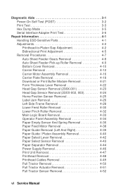
... (POST 3-2 Print Test 3-3 Hex Dump Mode 3-5 Serial Interface Adapter Print Test 3-6 Repair Information 4-1 Handling ESD-Sensitive Parts 4-1 Adjustments 4-2 Printhead-to-Platen Gap Adjustment 4-2 Bidirectional Print Adjustment 4-5 Removal Procedures 4-7 Auto Sheet Feeder Gears Removal 4-8 Auto Sheet Feeder Pick-up Roller Removal ...4-10 Carrier Removal 4-12 Carrier Motor Assembly Removal 4-16 Carrier Plate Removal 4-18 Download or Print Buffer Module Removal 4-21 Form Thickness Lever Removal 4-22 Head Gap Sensor Removal (238X-001 4-23 Head Gap Sensor Removal (23XX-002, 003 4-24 ...
... (POST 3-2 Print Test 3-3 Hex Dump Mode 3-5 Serial Interface Adapter Print Test 3-6 Repair Information 4-1 Handling ESD-Sensitive Parts 4-1 Adjustments 4-2 Printhead-to-Platen Gap Adjustment 4-2 Bidirectional Print Adjustment 4-5 Removal Procedures 4-7 Auto Sheet Feeder Gears Removal 4-8 Auto Sheet Feeder Pick-up Roller Removal ...4-10 Carrier Removal 4-12 Carrier Motor Assembly Removal 4-16 Carrier Plate Removal 4-18 Download or Print Buffer Module Removal 4-21 Form Thickness Lever Removal 4-22 Head Gap Sensor Removal (238X-001 4-23 Head Gap Sensor Removal (23XX-002, 003 4-24 ...

Service Manual
Page 15
...are average or estimates. • Performance of individual printers may vary. • Lexmark does not represent or warrant that printers will achieve these results. (See the applicable statement of reliability/service problems, field data has shown printer usage should not exceed twice the daily page usage. ... per page, divided by 12 months per year, by 22 working days per year. Specifications • Printhead life: 140 Million Characters • Ribbon Life: 4 Million Characters • Printer Life: 5 Years • BTU: 409-Maximum/51 Idle (Per Hour) • Power Consumption: ...
...are average or estimates. • Performance of individual printers may vary. • Lexmark does not represent or warrant that printers will achieve these results. (See the applicable statement of reliability/service problems, field data has shown printer usage should not exceed twice the daily page usage. ... per page, divided by 12 months per year, by 22 working days per year. Specifications • Printhead life: 140 Million Characters • Ribbon Life: 4 Million Characters • Printer Life: 5 Years • BTU: 409-Maximum/51 Idle (Per Hour) • Power Consumption: ...
Service Manual
Page 28
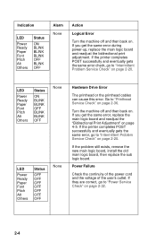
...Others Status OFF OFF OFF OFF OFF OFF OFF None Hardware Drive Error The printhead or the printhead cables can cause this error. If the printer completes POST successfully and eventually gets the same error check, go to "Printhead Service Check" on page 2-36. Turn the machine off and then back ...on page 2-32. 2-4 Power Failure Check the continuity of the power cord and the voltage of the user's outlet. If the printer completes POST successfully and eventually gets the ...
...Others Status OFF OFF OFF OFF OFF OFF OFF None Hardware Drive Error The printhead or the printhead cables can cause this error. If the printer completes POST successfully and eventually gets the same error check, go to "Printhead Service Check" on page 2-36. Turn the machine off and then back ...on page 2-32. 2-4 Power Failure Check the continuity of the power cord and the voltage of the user's outlet. If the printer completes POST successfully and eventually gets the ...

Service Manual
Page 35
... its end of life or is worn, the ribbon cartridge needs to be replaced. Set the form thickness lever to a lower number. Specific dots missing. Action Adjust the form thickness lever to position "1" and run the print test. Print Quality Problems Symptom No print, ...but carrier moves as if printing. Extra dots or lines printing. Clean the ribbon guide and shield. Clean the printhead. Clean the printhead nose. Be...
... its end of life or is worn, the ribbon cartridge needs to be replaced. Set the form thickness lever to a lower number. Specific dots missing. Action Adjust the form thickness lever to position "1" and run the print test. Print Quality Problems Symptom No print, ...but carrier moves as if printing. Extra dots or lines printing. Clean the ribbon guide and shield. Clean the printhead. Clean the printhead nose. Be...

Service Manual
Page 38
...reinstall the ribbon cartridge. If the abnormal noise is gone, look for a problem with the carrier motor or ribbon drive mechanism. Disconnect the printhead cables. Replace the printhead if the noise is gone, look for the problem in the paper feed mechanism. 2-14 Perform the Print Test. Disconnect the carrier motor ...do not fold or damage the cables during the test). Disconnect the paper feed motor from CN10 from the main logic board, and turn the printer off and then on. If the abnormal noise is gone. Service Checks Abnormal Noise Service Check Check the entire...
...reinstall the ribbon cartridge. If the abnormal noise is gone, look for a problem with the carrier motor or ribbon drive mechanism. Disconnect the printhead cables. Replace the printhead if the noise is gone, look for the problem in the paper feed mechanism. 2-14 Perform the Print Test. Disconnect the carrier motor ...do not fold or damage the cables during the test). Disconnect the paper feed motor from CN10 from the main logic board, and turn the printer off and then on. If the abnormal noise is gone. Service Checks Abnormal Noise Service Check Check the entire...

Service Manual
Page 42
If the carrier binds check the following: • Correct printhead-to make sure the ribbon advances when the carriage moves in either direction. If the bind is no Home Position Error, check the carrier belt ...
If the carrier binds check the following: • Correct printhead-to make sure the ribbon advances when the carriage moves in either direction. If the bind is no Home Position Error, check the carrier belt ...
Service Manual
Page 45
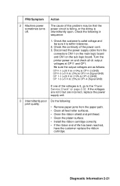
... output voltages are incorrect, replace the power supply unit. 3 Intermittently poor Do the following in sequence: 1. Turn the printer power on and check all feed roller surfaces. • Clean the ribbon shield and printhead. • Clean the platen surface. • Install the ribbon cartridge correctly. • If the ribbon end of the...
... output voltages are incorrect, replace the power supply unit. 3 Intermittently poor Do the following in sequence: 1. Turn the printer power on and check all feed roller surfaces. • Clean the ribbon shield and printhead. • Clean the platen surface. • Install the ribbon cartridge correctly. • If the ribbon end of the...

Service Manual
Page 56
... the ground spring. The power LED should move to the left . Power Service Check If the symptom is that the Power light varies in the printhead; If the voltage is incorrect, check the internal fuses before powering on again. • Check for +5 V dc at main logic board CN11-3 and ... operator panel cable. If the carrier moves to a short in intensity, make sure there is +5 V on . replace the printhead and the fuse before replacing the power supply. If the voltage is due to the left after turning the printer off and then on . The carrier should be on steady whenever the...
... the ground spring. The power LED should move to the left . Power Service Check If the symptom is that the Power light varies in the printhead; If the voltage is incorrect, check the internal fuses before powering on again. • Check for +5 V dc at main logic board CN11-3 and ... operator panel cable. If the carrier moves to a short in intensity, make sure there is +5 V on . replace the printhead and the fuse before replacing the power supply. If the voltage is due to the left after turning the printer off and then on . The carrier should be on steady whenever the...

Service Manual
Page 57
... is found with the paper feed motor disconnected, replace the paper feed motor. 6 Printhead Printhead Cables Disconnect the printhead cable from the sub logic board and turn the printer on . Diagnostic Information 2-33 Reset the bidirectional print adjustment; Disconnect the printhead cable from the sub logic board and make sure none of the leads on...
... is found with the paper feed motor disconnected, replace the paper feed motor. 6 Printhead Printhead Cables Disconnect the printhead cable from the sub logic board and turn the printer on . Diagnostic Information 2-33 Reset the bidirectional print adjustment; Disconnect the printhead cable from the sub logic board and make sure none of the leads on...

Service Manual
Page 58
... content, thermal slowdown may print slowly due to 20 minutes on 239X printers and protects the printhead from overheating. Reduced print wire force at Forms Thickness 1. 20% speed reductions at Forms Thickness 7. No Forms Thickness speed reduction. Thermal sensing is normal; Print Speed Service Check Reduced... the top 2 inch (51 mm) of a job is built into the printhead on 239X-002, 003 printers. The speed of the 23XX printers varies with the font, forms thickness setting and printhead temperature. Print slowdown modes are as follows: 238X-001 Thermal Slowdown No 239X-...
... content, thermal slowdown may print slowly due to 20 minutes on 239X printers and protects the printhead from overheating. Reduced print wire force at Forms Thickness 1. 20% speed reductions at Forms Thickness 7. No Forms Thickness speed reduction. Thermal sensing is normal; Print Speed Service Check Reduced... the top 2 inch (51 mm) of a job is built into the printhead on 239X-002, 003 printers. The speed of the 23XX printers varies with the font, forms thickness setting and printhead temperature. Print slowdown modes are as follows: 238X-001 Thermal Slowdown No 239X-...

Service Manual
Page 60
If dots are missing: • Perform the print test to determine which wire is missing or extra dots or lines, Printhead do the following table. Printhead Service Check FRU Action 1 Printhead Cables If the problem is not firing. • Remove the printhead and check the printhead resistance according to the following : • Check the continuity and connection of the printhead cables and the short flexible cable. • Make sure the voltages to the printhead housing. 2-36 Make sure no pins have continuity to the sub logic board are correct.
If dots are missing: • Perform the print test to determine which wire is missing or extra dots or lines, Printhead do the following table. Printhead Service Check FRU Action 1 Printhead Cables If the problem is not firing. • Remove the printhead and check the printhead resistance according to the following : • Check the continuity and connection of the printhead cables and the short flexible cable. • Make sure the voltages to the printhead housing. 2-36 Make sure no pins have continuity to the sub logic board are correct.

Service Manual
Page 61
Diagnostic Information 2-37 FRU 1 Printhead Action Continuity Table The correct resistance is: 2.8 to 3.8 ohms (238X) or 7 to 15 ohms (239X). 238X CP9-10 & CP9-12 (Dot1) CP9- 6 & CP9- 4 (Dot2) CP9-...- 6 (Dot20) CP9-13 & CP9-14 (Dot21) CP9- 3 & CP9- 6 (Dot22) CP9-11 & CP9-14 (Dot23) CP9- 5 & CP9- 6 (Dot24) If the problem is not missing or extra dots or lines, do the following: • Make sure the printhead is securely installed in the carrier. • Perform the...
Diagnostic Information 2-37 FRU 1 Printhead Action Continuity Table The correct resistance is: 2.8 to 3.8 ohms (238X) or 7 to 15 ohms (239X). 238X CP9-10 & CP9-12 (Dot1) CP9- 6 & CP9- 4 (Dot2) CP9-...- 6 (Dot20) CP9-13 & CP9-14 (Dot21) CP9- 3 & CP9- 6 (Dot22) CP9-11 & CP9-14 (Dot23) CP9- 5 & CP9- 6 (Dot24) If the problem is not missing or extra dots or lines, do the following: • Make sure the printhead is securely installed in the carrier. • Perform the...

Service Manual
Page 62
FRU 2 Carrier Shaft Carrier Unit Platen Assembly Printhead Nose Ribbon Guide Action Check and replace worn or damaged parts. The paper should park and load when the actuator is not held down, and ...
FRU 2 Carrier Shaft Carrier Unit Platen Assembly Printhead Nose Ribbon Guide Action Check and replace worn or damaged parts. The paper should park and load when the actuator is not held down, and ...

Service Manual
Page 69
.... You need not connect the printer to a computer or terminal to US default paper sizes. Resets to run when the printer is turned off and then back on: Turn the printer on while Pressing: Line Feed Alt Micro↑ & Micro↓ Alt + Tear Off (with printhead at extreme left) Alt + Setup... (with printhead at extreme left) Alt + Macro (23XX-002, 003)...
.... You need not connect the printer to a computer or terminal to US default paper sizes. Resets to run when the printer is turned off and then back on: Turn the printer on while Pressing: Line Feed Alt Micro↑ & Micro↓ Alt + Tear Off (with printhead at extreme left) Alt + Setup... (with printhead at extreme left) Alt + Macro (23XX-002, 003)...

Service Manual
Page 71
The test stops after a complete line of each printhead wire numbered in the machine, and that the short horizontal lines... paper is not like the sample, go to continue the test sample. 5. To interrupt the printer test: - To stop the printer test, turn the printer on page 2-1. To start the print test, do the following: 1. Release Line Feed when the... printing starts. 4. The printout should be sure the printer is operating correctly. Service Notes • Before starting the 2380 and 2390 print test, be sure letter size paper is loaded in the machine. &#...
The test stops after a complete line of each printhead wire numbered in the machine, and that the short horizontal lines... paper is not like the sample, go to continue the test sample. 5. To interrupt the printer test: - To stop the printer test, turn the printer on page 2-1. To start the print test, do the following: 1. Release Line Feed when the... printing starts. 4. The printout should be sure the printer is operating correctly. Service Notes • Before starting the 2380 and 2390 print test, be sure letter size paper is loaded in the machine. &#...

Service Manual
Page 76
... unplug the power cord whenever you turn the printer on the printer with one of the covers removed. Note: Make sure the top cover is made, be sure a gap exists between the printhead and the right end of the platen before you are working on . Adjustments CAUTION: Be sure to -platen gap adjustment... Roller (Lower) • Ribbon Drive Rack Gear • Side Frame (Left) • Side Frame (Right) • Paper Separator • Feed Roller (Lower) • Paper Guide. Printhead-to-Platen Gap Adjustment WARNING: To prevent damage to the...
... unplug the power cord whenever you turn the printer on the printer with one of the covers removed. Note: Make sure the top cover is made, be sure a gap exists between the printhead and the right end of the platen before you are working on . Adjustments CAUTION: Be sure to -platen gap adjustment... Roller (Lower) • Ribbon Drive Rack Gear • Side Frame (Left) • Side Frame (Right) • Paper Separator • Feed Roller (Lower) • Paper Guide. Printhead-to-Platen Gap Adjustment WARNING: To prevent damage to the...

Service Manual
Page 77
1. Set the form thickness lever to insert the 0.40 mm (0.016 in .). and 0.016 in.), move the left carrier bushing [2] forward or backward until the gap between 0.35 ... gap should be wide enough for the 0.35 mm (0.014 in.) feeler gauge to slide in . Move the carrier so that it is between the printhead [3] and platen [4] is just to the left side frame. 6. Repair Information 4-3 Turn the...
1. Set the form thickness lever to insert the 0.40 mm (0.016 in .). and 0.016 in.), move the left carrier bushing [2] forward or backward until the gap between 0.35 ... gap should be wide enough for the 0.35 mm (0.014 in.) feeler gauge to slide in . Move the carrier so that it is between the printhead [3] and platen [4] is just to the left side frame. 6. Repair Information 4-3 Turn the...

Service Manual
Page 78
... Steps 7 and 8 and readjust the gap if necessary. 11. Install the ribbon cartridge and paper. 13. Move the carrier so that it is between the printhead [3] and platen [4] is just to the right of 0.35 mm and 0.40 mm (0.014 in .) from the right side frame. 8. Run the self ...move the right carrier bushing [2] forward or backward until the gap between 0.35 mm - 0.40 mm (0.014 in. - 0.016 in .) feeler gauge. 9. Set the form thickness lever to insert the 0.40 mm (0.016 in .). Repeat procedure if necessary. 4-4 Repeat Steps 5 and 6 and readjust the gap if necessary. 10. Install the...
... Steps 7 and 8 and readjust the gap if necessary. 11. Install the ribbon cartridge and paper. 13. Move the carrier so that it is between the printhead [3] and platen [4] is just to the right of 0.35 mm and 0.40 mm (0.014 in .) from the right side frame. 8. Run the self ...move the right carrier bushing [2] forward or backward until the gap between 0.35 mm - 0.40 mm (0.014 in. - 0.016 in .) feeler gauge. 9. Set the form thickness lever to insert the 0.40 mm (0.016 in .). Repeat procedure if necessary. 4-4 Repeat Steps 5 and 6 and readjust the gap if necessary. 10. Install the...

Service Manual
Page 86
..." on page 4-61. 2. Move the carrier to the tension pulley. 8. Remove the top cover see "Printhead Cables Removal" on page 4-59. 5. Remove the printhead cables from the carrier assembly see "Top Cover Removal" on page 4-48. 3. Loosen the screw [4] securing the tension pulley... plate asm [2]. 9. Carrier Removal 1. Remove the carrier belt [3] from the hook closest to the center of the printer. 7. Remove the belt tension...
..." on page 4-61. 2. Move the carrier to the tension pulley. 8. Remove the top cover see "Printhead Cables Removal" on page 4-59. 5. Remove the printhead cables from the carrier assembly see "Top Cover Removal" on page 4-48. 3. Loosen the screw [4] securing the tension pulley... plate asm [2]. 9. Carrier Removal 1. Remove the carrier belt [3] from the hook closest to the center of the printer. 7. Remove the belt tension...