
Hardware Maintenance Manual
Page 6
...Installing or replacing a memory module . . . . 116 Replacing a PCI adapter card 118 Replacing the heat sink 121 Replacing the microprocessor 122 Replacing the system board 124 Replacing a hard disk drive 127 iv ThinkStation Hardware Maintenance Manual Replacing the hard disk drive fan assembly . . .... 130 Replacing an optical drive 131 Replacing the diskette drive or card reader . . . 132 Replacing the front and rear fan assemblies . . . 133 Replacing the front...
...Installing or replacing a memory module . . . . 116 Replacing a PCI adapter card 118 Replacing the heat sink 121 Replacing the microprocessor 122 Replacing the system board 124 Replacing a hard disk drive 127 iv ThinkStation Hardware Maintenance Manual Replacing the hard disk drive fan assembly . . .... 130 Replacing an optical drive 131 Replacing the diskette drive or card reader . . . 132 Replacing the front and rear fan assemblies . . . 133 Replacing the front...
Hardware Maintenance Manual
Page 77
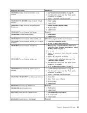
... the component that is called out is connected and/or enabled. If a component is connected and/or enabled 2. Go to -FRU Index 69 Check fans 2. Replace component under function test 1. See "Flash update procedures" on page 251 3. See "Flash update procedures" on page 41 2. System board... 185-000-XXX Asset Security Test Passed 185-XXX-XXX Asset Security failure 185-278-XXX Asset Security Chassis Intrusion 201-000-XXX System Memory Test Passed FRU/Action 1. Power supply 2. System board No action 1. Replace component under function test 1. System board 1. Make sure...
... the component that is called out is connected and/or enabled. If a component is connected and/or enabled 2. Go to -FRU Index 69 Check fans 2. Replace component under function test 1. See "Flash update procedures" on page 251 3. See "Flash update procedures" on page 41 2. System board... 185-000-XXX Asset Security Test Passed 185-XXX-XXX Asset Security failure 185-278-XXX Asset Security Chassis Intrusion 201-000-XXX System Memory Test Passed FRU/Action 1. Power supply 2. System board No action 1. Replace component under function test 1. System board 1. Make sure...
Hardware Maintenance Manual
Page 89
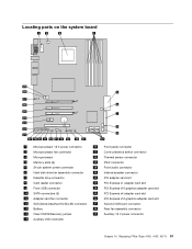
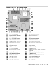
...power connector 16 Front panel connector 2 Microprocessor fan connector 17 Cover presence switch connector 3 Microprocessor 18 Thermal sensor connector 4 Memory slots (6) 19 PS/2 connector 5 24-pin system power connector 20 Front audio connector 6 Hard disk drive fan assembly connector 21 Internal speaker connector 7 Diskette...PCI Express x16 graphics adapter card slot 10 SATA connectors (5) 25 PCI Express x4 adapter card slot 11 Adapter card fan connector 26 PCI Express x16 graphics adapter card slot 12 SAS (Serial Attached SCSI) LED connector 27 Second COM port...
...power connector 16 Front panel connector 2 Microprocessor fan connector 17 Cover presence switch connector 3 Microprocessor 18 Thermal sensor connector 4 Memory slots (6) 19 PS/2 connector 5 24-pin system power connector 20 Front audio connector 6 Hard disk drive fan assembly connector 21 Internal speaker connector 7 Diskette...PCI Express x16 graphics adapter card slot 10 SATA connectors (5) 25 PCI Express x4 adapter card slot 11 Adapter card fan connector 26 PCI Express x16 graphics adapter card slot 12 SAS (Serial Attached SCSI) LED connector 27 Second COM port...

Hardware Maintenance Manual
Page 102
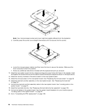
...in the figure: 94 ThinkStation Hardware Maintenance Manual Make sure you have a new retention module before opening the computer cover. Open the cover. Remove the memory modules from the failing system...sink into position and replace the 4 screws to secure the heat sink to : http://www.lenovo.com/support. See "Removing the cover" on page 86. 4. See "Replacing a PCI adapter card"... side for the microprocessor heat sink is required. Reconnect the heat sink fan cable. 11. Remove the hard disk drive fan. To replace the system board: 1. Remove the nine screws that came...
...in the figure: 94 ThinkStation Hardware Maintenance Manual Make sure you have a new retention module before opening the computer cover. Open the cover. Remove the memory modules from the failing system...sink into position and replace the 4 screws to secure the heat sink to : http://www.lenovo.com/support. See "Removing the cover" on page 86. 4. See "Replacing a PCI adapter card"... side for the microprocessor heat sink is required. Reconnect the heat sink fan cable. 11. Remove the hard disk drive fan. To replace the system board: 1. Remove the nine screws that came...
Hardware Maintenance Manual
Page 104
... any additional instructions included with those in the chassis. Install the memory modules in the figure above. 14. See "Replacing the microprocessor" on the new system board. 15. See "Replacing the hard disk drive fan assembly" on the new system board. Install the new system board...type at "Locating parts on the system board " on page 108. 96 ThinkStation Hardware Maintenance Manual e. Connect the heat sink and fan assembly cable to secure the retainer. Install the hard disk drive fan. d. Carefully press the socket cover straight downwards until it is securely locked ...
... any additional instructions included with those in the chassis. Install the memory modules in the figure above. 14. See "Replacing the microprocessor" on the new system board. 15. See "Replacing the hard disk drive fan assembly" on the new system board. Install the new system board...type at "Locating parts on the system board " on page 108. 96 ThinkStation Hardware Maintenance Manual e. Connect the heat sink and fan assembly cable to secure the retainer. Install the hard disk drive fan. d. Carefully press the socket cover straight downwards until it is securely locked ...
Hardware Maintenance Manual
Page 121
...CPU 1 memory slots (6) 2 Microprocessor and heat sink 1 3 CPU 1 fan connector 4 CPU 1 12 V power connector 5 CPU 1 memory fan connector 6 Microprocessor and heat sink 2 7 CPU 2 12 V power connector 8 24-pin power connector 9 CPU 2 fan connector 10 CPU 2 memory fan connector 11 CPU 2 memory slots ...(6) 12 Power switch/LEDs connector 13 Auxiliary LED connector 14 Hard disk drive fan connector 15 Diskette drive connector 16 Card reader connector ...
...CPU 1 memory slots (6) 2 Microprocessor and heat sink 1 3 CPU 1 fan connector 4 CPU 1 12 V power connector 5 CPU 1 memory fan connector 6 Microprocessor and heat sink 2 7 CPU 2 12 V power connector 8 24-pin power connector 9 CPU 2 fan connector 10 CPU 2 memory fan connector 11 CPU 2 memory slots ...(6) 12 Power switch/LEDs connector 13 Auxiliary LED connector 14 Hard disk drive fan connector 15 Diskette drive connector 16 Card reader connector ...
Hardware Maintenance Manual
Page 124
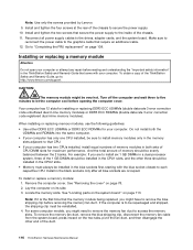
...: If it is to : http://www.lenovo.com/support. Note: Use only the screws provided by Lenovo. 9. Installing or replacing a memory module Attention Do not open your computer. Install and tighten the four screws at the rear of the ThinkStation Safety and Warranty Guide, go to be ... copy of the chassis to each respective CPU. Go to install memory modules only in the ThinkStation Safety and Warranty Guide that require an additional cable. 12. CAUTION: The memory module might need to remove the memory fan duct to remove the blue shipping clip before opening the computer cover...
...: If it is to : http://www.lenovo.com/support. Note: Use only the screws provided by Lenovo. 9. Installing or replacing a memory module Attention Do not open your computer. Install and tighten the four screws at the rear of the ThinkStation Safety and Warranty Guide, go to be ... copy of the chassis to each respective CPU. Go to install memory modules only in the ThinkStation Safety and Warranty Guide that require an additional cable. 12. CAUTION: The memory module might need to remove the memory fan duct to remove the blue shipping clip before opening the computer cover...
Hardware Maintenance Manual
Page 126
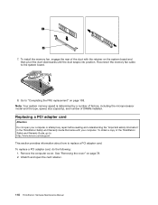
... the type, speed, size (capacity), and number of the ThinkStation Safety and Warranty Guide, go to the system board. 8. Remove the computer cover. Reconnect the memory fan cable to : http://www.lenovo.com/support. To replace a PCI adapter card, do the following: 1. To install the memory fan, engage the rear of the duct with your computer...
... the type, speed, size (capacity), and number of the ThinkStation Safety and Warranty Guide, go to the system board. 8. Remove the computer cover. Reconnect the memory fan cable to : http://www.lenovo.com/support. To replace a PCI adapter card, do the following: 1. To install the memory fan, engage the rear of the duct with your computer...
Hardware Maintenance Manual
Page 132
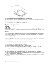
... system board to : http://www.lenovo.com/support. Reconnect the heat sink fan cable. 11. Remove the hard disk drive fan. Remove any repair before beginning this procedure. Replacing the system board CAUTION: The heat sink, microprocessor, and memory module might be very hot. Note the location of the ThinkStation Safety and Warranty Guide, go...
... system board to : http://www.lenovo.com/support. Reconnect the heat sink fan cable. 11. Remove the hard disk drive fan. Remove any repair before beginning this procedure. Replacing the system board CAUTION: The heat sink, microprocessor, and memory module might be very hot. Note the location of the ThinkStation Safety and Warranty Guide, go...

Hardware Maintenance Manual
Page 134
...with the replacement part you received. 13. See "Locating parts on the system board " on page 108. 126 ThinkStation Hardware Maintenance Manual Install the hard disk drive fan. Connect all cables to secure the retainer. Go to the new system board. Follow any additional instructions included with ...those in the figure above. 14. Install the memory modules in the same location on the new system board. Install the heat sink and fan assembly on the new system board. 15. See the system board illustration for your machine ...
...with the replacement part you received. 13. See "Locating parts on the system board " on page 108. 126 ThinkStation Hardware Maintenance Manual Install the hard disk drive fan. Connect all cables to secure the retainer. Go to the new system board. Follow any additional instructions included with ...those in the figure above. 14. Install the memory modules in the same location on the new system board. Install the heat sink and fan assembly on the new system board. 15. See the system board illustration for your machine ...

Hardware Maintenance Manual
Page 267
... connectors assembly, replacing 105, 134 H hard disk drive fan assembly, replacing 100, 130 hard disk drive, replacing 97, 127 I installing options memory 116 internal speaker, replacing 107, 137 © Copyright Lenovo 2008, 2012 L Lenovo Solution Center 35 M memory module, replacing 85 memory speed 257 O optical drive, replacing 101, 131 P ... 43 changing 41 viewing 41 Setup Utility 41 Setup Utility program, starting 41 Setup Utility, exiting 44 speed, memory 257 starting the Setup Utility program 41 startup device 43 sequence, changing 43 temporary, selecting 43 system board 259
... connectors assembly, replacing 105, 134 H hard disk drive fan assembly, replacing 100, 130 hard disk drive, replacing 97, 127 I installing options memory 116 internal speaker, replacing 107, 137 © Copyright Lenovo 2008, 2012 L Lenovo Solution Center 35 M memory module, replacing 85 memory speed 257 O optical drive, replacing 101, 131 P ... 43 changing 41 viewing 41 Setup Utility 41 Setup Utility program, starting 41 Setup Utility, exiting 44 speed, memory 257 starting the Setup Utility program 41 startup device 43 sequence, changing 43 temporary, selecting 43 system board 259

C&L 3 Belgium, Luxemburg - English, French, German, Dutch
Page 44
Self-service CRUs Diskette drive or card reader Hard disk drive Keyboard Memory module Mouse Optical drive Peripheral Component Interconnect (PCI) card Optional-service CRUs Battery Front panel connector assembly Hard disk drive fan assembly Heat sink and fan assembly Internal speaker Power supply assembly Rear system fan assembly 40 ThinkStation Safety and Warranty Guide You can find the CRU information in the ThinkStation Hardware Installation and Replacement Guide for the following machine types: 4155, 4158, and 4218.
Self-service CRUs Diskette drive or card reader Hard disk drive Keyboard Memory module Mouse Optical drive Peripheral Component Interconnect (PCI) card Optional-service CRUs Battery Front panel connector assembly Hard disk drive fan assembly Heat sink and fan assembly Internal speaker Power supply assembly Rear system fan assembly 40 ThinkStation Safety and Warranty Guide You can find the CRU information in the ThinkStation Hardware Installation and Replacement Guide for the following machine types: 4155, 4158, and 4218.
C&L 1 Pub Switzerland English-French-Greek-Italian
Page 44
Self-service CRUs Diskette drive or card reader Hard disk drive Keyboard Memory module Mouse Optical drive Peripheral Component Interconnect (PCI) card Optional-service CRUs Battery Front panel connector assembly Hard disk drive fan assembly Heat sink and fan assembly Internal speaker Power supply assembly Rear system fan assembly 40 ThinkStation Safety and Warranty Guide You can find the CRU information in the ThinkStation Hardware Installation and Replacement Guide for the following machine types: 4155, 4158, and 4218.
Self-service CRUs Diskette drive or card reader Hard disk drive Keyboard Memory module Mouse Optical drive Peripheral Component Interconnect (PCI) card Optional-service CRUs Battery Front panel connector assembly Hard disk drive fan assembly Heat sink and fan assembly Internal speaker Power supply assembly Rear system fan assembly 40 ThinkStation Safety and Warranty Guide You can find the CRU information in the ThinkStation Hardware Installation and Replacement Guide for the following machine types: 4155, 4158, and 4218.

C&L 2 Pub Nordics - English, Danish, Finnish, Norwegian, Swedish
Page 44
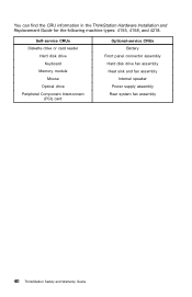
You can find the CRU information in the ThinkStation Hardware Installation and Replacement Guide for the following machine types: 4155, 4158, and 4218. Self-service CRUs Diskette drive or card reader Hard disk drive Keyboard Memory module Mouse Optical drive Peripheral Component Interconnect (PCI) card Optional-service CRUs Battery Front panel connector assembly Hard disk drive fan assembly Heat sink and fan assembly Internal speaker Power supply assembly Rear system fan assembly 40 ThinkStation Safety and Warranty Guide
You can find the CRU information in the ThinkStation Hardware Installation and Replacement Guide for the following machine types: 4155, 4158, and 4218. Self-service CRUs Diskette drive or card reader Hard disk drive Keyboard Memory module Mouse Optical drive Peripheral Component Interconnect (PCI) card Optional-service CRUs Battery Front panel connector assembly Hard disk drive fan assembly Heat sink and fan assembly Internal speaker Power supply assembly Rear system fan assembly 40 ThinkStation Safety and Warranty Guide


