(English) Rescue and Recovery 4.3 Deployment Guide
Page 14
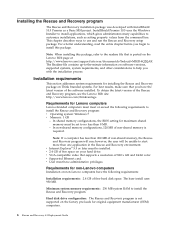
... Rescue and Recovery program will be installed. Minimum system memory requirements: 256 MB system RAM to install this package, refer to the readme file that is posted on the Lenovo Web page at: http://www.lenovo.com/support/site.wss/document.do?lndocid=MIGR-4Q2QAK The Readme file contains up-to-the-minute...
... Rescue and Recovery program will be installed. Minimum system memory requirements: 256 MB system RAM to install this package, refer to the readme file that is posted on the Lenovo Web page at: http://www.lenovo.com/support/site.wss/document.do?lndocid=MIGR-4Q2QAK The Readme file contains up-to-the-minute...
(English) Rescue and Recovery 4.3 Deployment Guide
Page 15
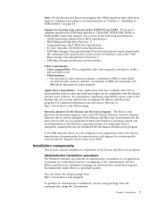
...Mass Storage Class Specification Overview (Each device must be configured according to add support for video memory. For additional information see the Lenovo Web site at: http://www.lenovo.com/thinkvantage Network adapters for boot-ability Video requirements: v Video compatibility: VGA-compatible video ...supports a resolution of 800 x 600 and 24-bit color v Video memory: - Installation components This section contains installation components of 8 MB can obtain the setup package from: http://www.lenovo.com/support To perform an administrative installation, run the setup package from ...
...Mass Storage Class Specification Overview (Each device must be configured according to add support for video memory. For additional information see the Lenovo Web site at: http://www.lenovo.com/thinkvantage Network adapters for boot-ability Video requirements: v Video compatibility: VGA-compatible video ...supports a resolution of 800 x 600 and 24-bit color v Video memory: - Installation components This section contains installation components of 8 MB can obtain the setup package from: http://www.lenovo.com/support To perform an administrative installation, run the setup package from ...
(English) Rescue and Recovery 4.3 Deployment Guide
Page 59
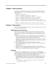
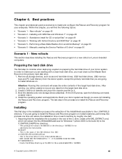
... c:\SWTOOLS for CD or script files" on page 57 v "Scenario 6 - Standalone install for an :: administrative installation. © Copyright Lenovo 2008, 2009 51 Performing a Bare Metal Restore from the donor system, except the primary hard disk that the installation file is located in the...in the root of your enterprise. Build your donor system as second hard disk drives, USB hard disk drives, USB memory keys and PC Card Memory from an Admin Backup" on multiple systems, performing this process one storage device attached). Best practices This chapter provides best...
... c:\SWTOOLS for CD or script files" on page 57 v "Scenario 6 - Standalone install for an :: administrative installation. © Copyright Lenovo 2008, 2009 51 Performing a Bare Metal Restore from the donor system, except the primary hard disk that the installation file is located in the...in the root of your enterprise. Build your donor system as second hard disk drives, USB hard disk drives, USB memory keys and PC Card Memory from an Admin Backup" on multiple systems, performing this process one storage device attached). Best practices This chapter provides best...
(English) Rescue and Recovery 4.5 Deployment Guide
Page 10
... Installation components This section contains installation components of non-shared memory, the Rescue and Recovery program will be unable to specify the locations for Lenovo computers To install the Rescue and Recovery program, Lenovo-branded computers must be set the public property TARGETDIR on ... prompts the administrative user to start more than C:\. In non-shared memory configurations, 120 MB of the software installed. however, the user will run the setup package from : http://support.lenovo.com To perform an administrative installation, run ; You can also create...
... Installation components This section contains installation components of non-shared memory, the Rescue and Recovery program will be unable to specify the locations for Lenovo computers To install the Rescue and Recovery program, Lenovo-branded computers must be set the public property TARGETDIR on ... prompts the administrative user to start more than C:\. In non-shared memory configurations, 120 MB of the software installed. however, the user will run the setup package from : http://support.lenovo.com To perform an administrative installation, run ; You can also create...
(English) Rescue and Recovery 4.5 Deployment Guide
Page 51
... program in the installation process is the drive letter for your donor system as second hard disk drives, USB hard disk drives, USB memory keys and PC Card Memory from an Admin Backup" on page 50 Scenario 1 - At the DOS prompt, type the following topics: • "Scenario 1 -...is the extraction of the target hard disk drive. Build your enterprise. Standalone install for the exploded WWW EXMD c:\SWTOOLS © Copyright Lenovo 2008, 2011 45 Attention: Running this process one time will erase the entire contents of the InstallShield executable to recover any data from ...
... program in the installation process is the drive letter for your donor system as second hard disk drives, USB hard disk drives, USB memory keys and PC Card Memory from an Admin Backup" on page 50 Scenario 1 - At the DOS prompt, type the following topics: • "Scenario 1 -...is the extraction of the target hard disk drive. Build your enterprise. Standalone install for the exploded WWW EXMD c:\SWTOOLS © Copyright Lenovo 2008, 2011 45 Attention: Running this process one time will erase the entire contents of the InstallShield executable to recover any data from ...

Hardware Maintenance Manual
Page 6
... 110 Locations 111 Locating parts on the system board 81 Removing the front bezel 82 Replacing the power supply 82 Replacing a memory module 84 Replacing a PCI adapter card 86 Replacing the heat sink 90 Replacing the microprocessor 92 Replacing the system board 94... Replacing the power supply 114 Installing or replacing a memory module . . . . 116 Replacing a PCI adapter card 118 Replacing the heat sink 121 Replacing the microprocessor 122 Replacing the system board 124 Replacing a hard disk drive 127 iv ThinkStation Hardware Maintenance Manual Replacing the hard disk drive fan...
... 110 Locations 111 Locating parts on the system board 81 Removing the front bezel 82 Replacing the power supply 82 Replacing a memory module 84 Replacing a PCI adapter card 86 Replacing the heat sink 90 Replacing the microprocessor 92 Replacing the system board 94... Replacing the power supply 114 Installing or replacing a memory module . . . . 116 Replacing a PCI adapter card 118 Replacing the heat sink 121 Replacing the microprocessor 122 Replacing the system board 124 Replacing a hard disk drive 127 iv ThinkStation Hardware Maintenance Manual Replacing the hard disk drive fan...

Hardware Maintenance Manual
Page 50
... diskette A When this feature, make sure your system has an alternate boot method, such as LAN PXE boot, or a bootable floppy diskette, memory key, or optical disc. When disabling this feature is set, it deters unauthorized persons from the Setup Utility program menu. 3. Start the Setup ... be used until a valid password is set to the Setup Utility program menu and select Exit ® Save and exit the Setup Utility. 42 ThinkStation Hardware Maintenance Manual If you might want to change , or delete a password, do the following : Note: A password can type either Devices ®...
... diskette A When this feature, make sure your system has an alternate boot method, such as LAN PXE boot, or a bootable floppy diskette, memory key, or optical disc. When disabling this feature is set, it deters unauthorized persons from the Setup Utility program menu. 3. Start the Setup ... be used until a valid password is set to the Setup Utility program menu and select Exit ® Save and exit the Setup Utility. 42 ThinkStation Hardware Maintenance Manual If you might want to change , or delete a password, do the following : Note: A password can type either Devices ®...
Hardware Maintenance Manual
Page 62
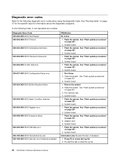
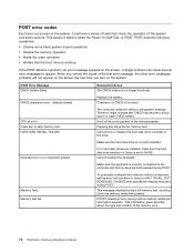
...procedures" on page 251 2. Diagnostic error codes Refer to the following index, X can represent any number. Flash the system. Run Setup 2. Run memory test 4. System board 1. See "Flash update procedures" on page 251 2. See "Flash update procedures" on page 251 2. System board 1. ...page 251 3. Flash the system. System board 1. Flash the system. System board 1. Press F3 to reset the log file 54 ThinkStation Hardware Maintenance Manual Flash the system. Flash the system. System board Information only Re-start the test to review the log file 2. ...
...procedures" on page 251 2. Diagnostic error codes Refer to the following index, X can represent any number. Flash the system. Run Setup 2. Run memory test 4. System board 1. See "Flash update procedures" on page 251 2. See "Flash update procedures" on page 251 2. System board 1. ...page 251 3. Flash the system. System board 1. Flash the system. System board 1. Press F3 to reset the log file 54 ThinkStation Hardware Maintenance Manual Flash the system. Flash the system. System board Information only Re-start the test to review the log file 2. ...
Hardware Maintenance Manual
Page 63
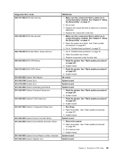
... 3. See "Flash update procedures" on page 251 2. Flash the system. Re-run test 3. Replace component under test 1. See "Flash update procedures" on page 251 2. Run memory test 4. Make sure the component that is called out is connected and/or enabled. See Chapter 6 "Using the Setup Utility" on page 41 2. See Chapter...
... 3. See "Flash update procedures" on page 251 2. Flash the system. Re-run test 3. Replace component under test 1. See "Flash update procedures" on page 251 2. Run memory test 4. Make sure the component that is called out is connected and/or enabled. See Chapter 6 "Using the Setup Utility" on page 41 2. See Chapter...
Hardware Maintenance Manual
Page 69
... to -FRU Index 61 System board No action 1. Remove USB device(s) and re-test 2. System board 1. System board 1. Flash the system and re-test. Run memory test 4. System board System board 1. Run setup and check for conflicts 2. Make sure the component that is called out, make sure it is connected and...
... to -FRU Index 61 System board No action 1. Remove USB device(s) and re-test 2. System board 1. System board 1. Flash the system and re-test. Run memory test 4. System board System board 1. Run setup and check for conflicts 2. Make sure the component that is called out, make sure it is connected and...
Hardware Maintenance Manual
Page 77
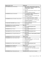
... error 185-000-XXX Asset Security Test Passed 185-XXX-XXX Asset Security failure 185-278-XXX Asset Security Chassis Intrusion 201-000-XXX System Memory Test Passed FRU/Action 1. See Chapter 6 "Using the Setup Utility" on page 251 3. Microprocessor 4. See "Undetermined problems" on page 75...
... error 185-000-XXX Asset Security Test Passed 185-XXX-XXX Asset Security failure 185-278-XXX Asset Security Chassis Intrusion 201-000-XXX System Memory Test Passed FRU/Action 1. See Chapter 6 "Using the Setup Utility" on page 251 3. Microprocessor 4. See "Undetermined problems" on page 75...
Hardware Maintenance Manual
Page 78
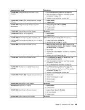
...System board 1. Keyboard 2. System board No action No action 1. System board No action Remove the Joystick and re-test the system 70 ThinkStation Hardware Maintenance Manual Replace the memory module called out by the test 2. Diskette Drive Cable 2. SCSI adapter card 6. Check and test mouse 3. Mouse 2. Check power supply... system 1. Cache, if removable 2. Hard Disk Drive Cable 2. System board No action 1. Diagnostic Error Code 201-XXX-XXX System Memory error 202-000-XXX System Cache Test Passed 202-XXX-XXX System Cache error 206-000-XXX Diskette Drive Test Passed 206-XXX-XXX...
...System board 1. Keyboard 2. System board No action No action 1. System board No action Remove the Joystick and re-test the system 70 ThinkStation Hardware Maintenance Manual Replace the memory module called out by the test 2. Diskette Drive Cable 2. SCSI adapter card 6. Check and test mouse 3. Mouse 2. Check power supply... system 1. Cache, if removable 2. Hard Disk Drive Cable 2. System board No action 1. Diagnostic Error Code 201-XXX-XXX System Memory error 202-000-XXX System Cache Test Passed 202-XXX-XXX System Cache error 206-000-XXX Diskette Drive Test Passed 206-XXX-XXX...
Hardware Maintenance Manual
Page 79
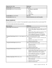
...beeps Monitor or video adapter card error 1 long and 3 short beeps Keyboard error 1 long and 9 short beeps BIOS ROM error Continuos long beeps DRAM memory error FRU/Action Perform the following actions in order. 1. See Chapter 6 "Using the Setup Utility" on page 252. 3. See "Recovering from a...FRU Index 71 Replace the system board. Symptom-to Save and exit. Perform the following actions in order. 1. Make sure the memory module(s) are tones or a series of tones separated by pauses (intervals without sound) during POST. Perform the following actions in order. 1....
...beeps Monitor or video adapter card error 1 long and 3 short beeps Keyboard error 1 long and 9 short beeps BIOS ROM error Continuos long beeps DRAM memory error FRU/Action Perform the following actions in order. 1. See Chapter 6 "Using the Setup Utility" on page 252. 3. See "Recovering from a...FRU Index 71 Replace the system board. Symptom-to Save and exit. Perform the following actions in order. 1. Make sure the memory module(s) are tones or a series of tones separated by pauses (intervals without sound) during POST. Perform the following actions in order. 1....
Hardware Maintenance Manual
Page 80
... Keyboard error or no longer functional. Cannot initialize the keyboard. Replace the battery. When you correct the cause of the memory error. 72 ThinkStation Hardware Maintenance Manual Pressing Esc skips the full memory test Cannot find or initialize the hard disk drive controller or the drive. defaults loaded CPU at nnnn Press Esc...
... Keyboard error or no longer functional. Cannot initialize the keyboard. Replace the battery. When you correct the cause of the memory error. 72 ThinkStation Hardware Maintenance Manual Pressing Esc skips the full memory test Cannot find or initialize the hard disk drive controller or the drive. defaults loaded CPU at nnnn Press Esc...

Hardware Maintenance Manual
Page 81
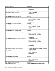
...startup sequence as first device or first device after diskette 2. Diskette Drive 2. System Board 2. Hard Disk Drive Cable Incorrect memory size during POST 1. Miscellaneous error messages Message/Symptom FRU/Action Changing display colors Display/Monitor Computer will not perform a ... active. 1. Ensure no interrupt or I/O address conflicts 6. Diskette Drive Cable Flashing cursor with an otherwise blank display. 1. Run the Memory tests 2. System Board Chapter 9. Power Supply 2. System Board 3. Ensure that network adapter is in Setup/Configuration (see "Starting the ...
...startup sequence as first device or first device after diskette 2. Diskette Drive 2. System Board 2. Hard Disk Drive Cable Incorrect memory size during POST 1. Miscellaneous error messages Message/Symptom FRU/Action Changing display colors Display/Monitor Computer will not perform a ... active. 1. Ensure no interrupt or I/O address conflicts 6. Diskette Drive Cable Flashing cursor with an otherwise blank display. 1. Run the Memory tests 2. System Board Chapter 9. Power Supply 2. System Board 3. Ensure that network adapter is in Setup/Configuration (see "Starting the ...

Hardware Maintenance Manual
Page 83
Power-off the computer. 2. Extended video memory e. Hard disk drive h. If all devices and adapters have been removed, and the problem continues, replace the system board. Undetermined problems If this computer has a ... jumpered as a master and the optical drive is jumpered as a slave. 1. Diskette drive 3. Repeat steps 1 through 3 until you find the failing device or adapter. Chapter 9. Memory modules d. Remove or disconnect the following components (if installed) one at a time. Power-on the computer to -FRU Index 75 External devices (modem, printer, or...
Power-off the computer. 2. Extended video memory e. Hard disk drive h. If all devices and adapters have been removed, and the problem continues, replace the system board. Undetermined problems If this computer has a ... jumpered as a master and the optical drive is jumpered as a slave. 1. Diskette drive 3. Repeat steps 1 through 3 until you find the failing device or adapter. Chapter 9. Memory modules d. Remove or disconnect the following components (if installed) one at a time. Power-on the computer to -FRU Index 75 External devices (modem, printer, or...
Hardware Maintenance Manual
Page 89
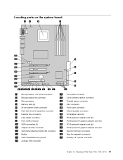
... on the system board 1 Microprocessor 12 V power connector 16 Front panel connector 2 Microprocessor fan connector 17 Cover presence switch connector 3 Microprocessor 18 Thermal sensor connector 4 Memory slots (6) 19 PS/2 connector 5 24-pin system power connector 20 Front audio connector 6 Hard disk drive fan assembly connector 21 Internal speaker connector 7 Diskette drive...
... on the system board 1 Microprocessor 12 V power connector 16 Front panel connector 2 Microprocessor fan connector 17 Cover presence switch connector 3 Microprocessor 18 Thermal sensor connector 4 Memory slots (6) 19 PS/2 connector 5 24-pin system power connector 20 Front audio connector 6 Hard disk drive fan assembly connector 21 Internal speaker connector 7 Diskette drive...
Hardware Maintenance Manual
Page 92
Ensure that came with those in the ThinkStation Safety and Warranty Guide that the new power supply is a voltage-...in the chassis. Reconnect all power supply cables to : http://www.lenovo.com/support. 84 ThinkStation Hardware Maintenance Manual 7. Note: Use only the screws provided by Lenovo. 9. Some power supplies automatically sense the voltage, some power supplies ...models that require an additional cable. 10. Install and tighten the five screws at the rear of the ThinkStation Safety and Warranty Guide, go to the drives, adapter cards, and the system board. Go to ...
Ensure that came with those in the ThinkStation Safety and Warranty Guide that the new power supply is a voltage-...in the chassis. Reconnect all power supply cables to : http://www.lenovo.com/support. 84 ThinkStation Hardware Maintenance Manual 7. Note: Use only the screws provided by Lenovo. 9. Some power supplies automatically sense the voltage, some power supplies ...models that require an additional cable. 10. Install and tighten the five screws at the rear of the ThinkStation Safety and Warranty Guide, go to the drives, adapter cards, and the system board. Go to ...
Hardware Maintenance Manual
Page 93
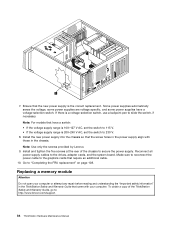
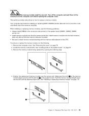
...on the system board (DIMM1, DIMM2, DIMM3, and so on the system board. Chapter 10. Push the memory module straight down into the blue memory slots first. CAUTION: The memory module might be very hot. See "Locating parts on the system board " on how to let the ...computer cool before opening the retaining clips. 4. Make sure the notch 1 on the memory module aligns correctly with the memory slots adjacent to install memory modules starting with the slot key 2 on ). • Install memory modules into the slot until the retaining clips close. Replacing FRUs (Type 4105, 4157...
...on the system board (DIMM1, DIMM2, DIMM3, and so on the system board. Chapter 10. Push the memory module straight down into the blue memory slots first. CAUTION: The memory module might be very hot. See "Locating parts on the system board " on how to let the ...computer cool before opening the retaining clips. 4. Make sure the notch 1 on the memory module aligns correctly with the memory slots adjacent to install memory modules starting with the slot key 2 on ). • Install memory modules into the slot until the retaining clips close. Replacing FRUs (Type 4105, 4157...

Hardware Maintenance Manual
Page 102
... 1. Lay the computer on page 108. Remove any repair before reading and understanding the "Important safety information" in the PCI connectors. Remove the memory modules from the failing system board. See "Locating parts on the system board " on page 86. 4. Note: When replacing the system board ...board. See "Replacing a PCI adapter card" on page 81. 8. Open the cover. Note the location of the ThinkStation Safety and Warranty Guide, go to: http://www.lenovo.com/support. Replacing the system board CAUTION: The heat sink and microprocessor might be very hot. Remove the heat ...
... 1. Lay the computer on page 108. Remove any repair before reading and understanding the "Important safety information" in the PCI connectors. Remove the memory modules from the failing system board. See "Locating parts on the system board " on page 86. 4. Note: When replacing the system board ...board. See "Replacing a PCI adapter card" on page 81. 8. Open the cover. Note the location of the ThinkStation Safety and Warranty Guide, go to: http://www.lenovo.com/support. Replacing the system board CAUTION: The heat sink and microprocessor might be very hot. Remove the heat ...


