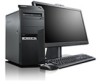
BIOS Windows Management Instrumentation Interface Deployment Guide
Page 34
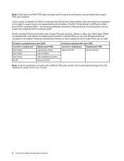
...of Microsoft Corporation in the United States, other countries, or both . Trademarks The following terms are trademarks of Lenovo in the United States, other countries, or both : Lenovo the Lenovo logo Thinkcentre ThinkVantage Microsoft, Windows, Windows Vista, and Active Directory are provided for convenience only and do not in any ...Other company, product, or service names may be trademarks or service marks of the materials for Desktop 26 Any references in this Lenovo product, and use of those Web sites is at your own risk. The materials at those Web sites are not part of others.
...of Microsoft Corporation in the United States, other countries, or both . Trademarks The following terms are trademarks of Lenovo in the United States, other countries, or both : Lenovo the Lenovo logo Thinkcentre ThinkVantage Microsoft, Windows, Windows Vista, and Active Directory are provided for convenience only and do not in any ...Other company, product, or service names may be trademarks or service marks of the materials for Desktop 26 Any references in this Lenovo product, and use of those Web sites is at your own risk. The materials at those Web sites are not part of others.
Hardware Maintenance Manual
Page 5
...Lenovo Solution Center 37 PC-Doctor for power problems 33 Problem determination tips 34 Chapter 5. Replacing FRUs 69 Locations 69 Locating connectors, controls, and indicators on the front of your computer 69 Locating connectors on the rear of your computer 70 Locating components 71 Locating parts... . . . . . 6 Chapter 3. General information . . . . 29 Lenovo Welcome 29 Lenovo ThinkVantage Tools 29 Lenovo ThinkVantage Toolbox 29 SimpleTap 29 Lenovo Solution Center 30 ThinkVantage Productivity Center 30 Additional information resources 30 Specifications 31 Chapter 4. ...
...Lenovo Solution Center 37 PC-Doctor for power problems 33 Problem determination tips 34 Chapter 5. Replacing FRUs 69 Locations 69 Locating connectors, controls, and indicators on the front of your computer 69 Locating connectors on the rear of your computer 70 Locating components 71 Locating parts... . . . . . 6 Chapter 3. General information . . . . 29 Lenovo Welcome 29 Lenovo ThinkVantage Tools 29 Lenovo ThinkVantage Toolbox 29 SimpleTap 29 Lenovo Solution Center 30 ThinkVantage Productivity Center 30 Additional information resources 30 Specifications 31 Chapter 4. ...
Hardware Maintenance Manual
Page 7
... and reference information for ThinkCentre® computer machine types listed on the front cover. Products on the market before June, 2006 are not compliant originally, replacement parts can also be compliant. © Copyright Lenovo 2011, 2012 1 If the parts are not required to ...instructions. This manual includes a complete FRU part number list for trained servicers who are also available at: http://www.lenovo.com/support Important safety information Be sure to have Internet access, the FRU part numbers are familiar with Lenovo® computer products. Lesen Sie unbedingt...
... and reference information for ThinkCentre® computer machine types listed on the front cover. Products on the market before June, 2006 are not compliant originally, replacement parts can also be compliant. © Copyright Lenovo 2011, 2012 1 If the parts are not required to ...instructions. This manual includes a complete FRU part number list for trained servicers who are also available at: http://www.lenovo.com/support Important safety information Be sure to have Internet access, the FRU part numbers are familiar with Lenovo® computer products. Lesen Sie unbedingt...
Hardware Maintenance Manual
Page 8
... shipped by the distribution center at the time of order. 2 ThinkCentre Hardware Maintenance Manual Before or after June 2006 Current or original part Replacement FRU Must be RoHS Must be ready to these products and any product Lenovo produces containing RoHS compliant parts. Lenovo plans to transition to RoHS compliance well before June 2006 Current...
... shipped by the distribution center at the time of order. 2 ThinkCentre Hardware Maintenance Manual Before or after June 2006 Current or original part Replacement FRU Must be RoHS Must be ready to these products and any product Lenovo produces containing RoHS compliant parts. Lenovo plans to transition to RoHS compliance well before June 2006 Current...
Hardware Maintenance Manual
Page 9
... up with your sleeves are : hammering, drilling soldering, cutting wire, attaching springs, using solvents, or working on electrical equipment. © Copyright Lenovo 2011, 2012 3 Never move suddenly or twist when you need to be hazardous. Lift by standing or by pushing up above your feet. 3....'s personnel are not in a hazardous position. • Place removed covers and other parts in a safe place, away from walk areas so that other conditions that might be trapped in the moving parts of the object equally between your elbows. Observe the following rules when working in your...
... up with your sleeves are : hammering, drilling soldering, cutting wire, attaching springs, using solvents, or working on electrical equipment. © Copyright Lenovo 2011, 2012 3 Never move suddenly or twist when you need to be hazardous. Lift by standing or by pushing up above your feet. 3....'s personnel are not in a hazardous position. • Place removed covers and other parts in a safe place, away from walk areas so that other conditions that might be trapped in the moving parts of the object equally between your elbows. Observe the following rules when working in your...
Hardware Maintenance Manual
Page 10
...conductive; Remember: Another person must be there to switch off the wall box that has exposed electrical circuits, observe the following parts with very high voltages; these hazards are moist floors, nongrounded power extension cables, power surges, and missing safety grounds. &#... with live electrical circuits with powered-on electrical equipment; Remember: There must be a complete circuit to get medical aid. 4 ThinkCentre Hardware Maintenance Manual The surface is near equipment that does not insulate you need to protect yourself from a circuit. do not become ...
...conductive; Remember: Another person must be there to switch off the wall box that has exposed electrical circuits, observe the following parts with very high voltages; these hazards are moist floors, nongrounded power extension cables, power surges, and missing safety grounds. &#... with live electrical circuits with powered-on electrical equipment; Remember: There must be a complete circuit to get medical aid. 4 ThinkCentre Hardware Maintenance Manual The surface is near equipment that does not insulate you need to protect yourself from a circuit. do not become ...
Hardware Maintenance Manual
Page 11
... less between the external ground pin and frame ground. Consider these products. Power-off , and the power cord disconnected. A third-wire ground connector in the parts listings. c. If your electrical outlet. Each machine, as it was originally purchased. Checklist: 1. Use a meter to assist you are located. If your local electric company...
... less between the external ground pin and frame ground. Consider these products. Power-off , and the power cord disconnected. A third-wire ground connector in the parts listings. c. If your electrical outlet. Each machine, as it was originally purchased. Checklist: 1. Use a meter to assist you are located. If your local electric company...
Hardware Maintenance Manual
Page 12
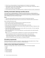
... fasteners (screws or rivets) have been certified (ISO 9000) as those listed below, to electrostatic discharge (ESD). Notes: 1. When handling ESD-sensitive parts: • Keep the parts in this section are inserted into the product. • Avoid contact with . You can be considered sensitive to provide protection that the machine, the... green-wire ground. - Most clothing is a difference in the following languages: • English • Arabic • Brazilian/Portuguese • Chinese (simplified) • Chinese (traditional) 6 ThinkCentre Hardware Maintenance Manual
... fasteners (screws or rivets) have been certified (ISO 9000) as those listed below, to electrostatic discharge (ESD). Notes: 1. When handling ESD-sensitive parts: • Keep the parts in this section are inserted into the product. • Avoid contact with . You can be considered sensitive to provide protection that the machine, the... green-wire ground. - Most clothing is a difference in the following languages: • English • Arabic • Brazilian/Portuguese • Chinese (simplified) • Chinese (traditional) 6 ThinkCentre Hardware Maintenance Manual
Hardware Maintenance Manual
Page 13
... 2. Attach signal cables to outlet. 5. Remove all cables to connect or disconnect signal cables. • Never turn on this product. • When possible, use only Part Number 45C1566 or an equivalent type battery recommended by the same manufacturer. First, attach all cables from devices. To Disconnect 1. Safety information 7 If your system...
... 2. Attach signal cables to outlet. 5. Remove all cables to connect or disconnect signal cables. • Never turn on this product. • When possible, use only Part Number 45C1566 or an equivalent type battery recommended by the same manufacturer. First, attach all cables from devices. To Disconnect 1. Safety information 7 If your system...
Hardware Maintenance Manual
Page 14
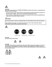
... the covers. To remove all electrical current from the device, ensure that all power cords are disconnected from the power source. 2 1 8 ThinkCentre Hardware Maintenance Manual There are no serviceable parts inside the device. • Use of controls or adjustments or performance of the laser product could result in hazardous radiation exposure. Removing...
... the covers. To remove all electrical current from the device, ensure that all power cords are disconnected from the power source. 2 1 8 ThinkCentre Hardware Maintenance Manual There are no serviceable parts inside the device. • Use of controls or adjustments or performance of the laser product could result in hazardous radiation exposure. Removing...

Hardware Maintenance Manual
Page 36
...SimpleTap program, you can find the following information: • CRU removal and installation instructions • Downloads and drivers • Parts information • Publications • Troubleshooting information • Links to troubleshoot and resolve computer problems. It combines diagnostic tests, system...resources If you to other useful sources of information 30 ThinkCentre Hardware Maintenance Manual Note: The SimpleTap program is available at: http://www.lenovo.com/support You can download it from Lenovo. • Press the blue ThinkVantage button if your ...
...SimpleTap program, you can find the following information: • CRU removal and installation instructions • Downloads and drivers • Parts information • Publications • Troubleshooting information • Links to troubleshoot and resolve computer problems. It combines diagnostic tests, system...resources If you to other useful sources of information 30 ThinkCentre Hardware Maintenance Manual Note: The SimpleTap program is available at: http://www.lenovo.com/support You can download it from Lenovo. • Press the blue ThinkVantage button if your ...
Hardware Maintenance Manual
Page 40
... are considered identical only if they: 1. Are the exact machine type and models 2. Verify that can be encountered, use - See "Locating parts on the system board" on page 72. 9. Reseat the cable from the AC/DC power adapter to the computer is properly connected. Problem ...eliminate confusion, identical systems are using a good AC power outlet. Do diagnostics indicate a failure? - Have the same address jumpers/terminators/cabling 34 ThinkCentre Hardware Maintenance Manual Check the status of the power indicator LED on the AC/DC power adapter. • If the LED is illuminated (on...
... are considered identical only if they: 1. Are the exact machine type and models 2. Verify that can be encountered, use - See "Locating parts on the system board" on page 72. 9. Reseat the cable from the AC/DC power adapter to the computer is properly connected. Problem ...eliminate confusion, identical systems are using a good AC power outlet. Do diagnostics indicate a failure? - Have the same address jumpers/terminators/cabling 34 ThinkCentre Hardware Maintenance Manual Check the status of the power indicator LED on the AC/DC power adapter. • If the LED is illuminated (on...
Hardware Maintenance Manual
Page 49
...through step 2. 8. See "Opening the computer cover" on page 98. 6. Close the computer cover and connect the power cord. See "Completing the parts replacement" on page 72. 3. Move the Clear CMOS /Recovery jumper back to the USB connector cannot be used. See "Exiting from the drives and...Clear CMOS /Recovery jumper on for approximately five seconds. 7. Turn on the computer and leave it on the system board. See "Completing the parts replacement" on page 41. 2. Enabling or disabling a device This section provides information on the device you want to enable or disable, do ...
...through step 2. 8. See "Opening the computer cover" on page 98. 6. Close the computer cover and connect the power cord. See "Completing the parts replacement" on page 72. 3. Move the Clear CMOS /Recovery jumper back to the USB connector cannot be used. See "Exiting from the drives and...Clear CMOS /Recovery jumper on for approximately five seconds. 7. Turn on the computer and leave it on the system board. See "Completing the parts replacement" on page 41. 2. Enabling or disabling a device This section provides information on the device you want to enable or disable, do ...
Hardware Maintenance Manual
Page 53
...tests" on the failing hard disk drive. 2. Always begin with the Chapter 4 "General checkout" on the start -up drive is in the first part of your operating system is corrupted. If you have the following : 1. Attempt to "Undetermined problems" on in another location. • If the... disappears before you did receive a POST error message, diagnose the POST error message first. 3. You can represent any number. © Copyright Lenovo 2011, 2012 47 If you are needed when servicing a computer. Press F1 to -FRU index lists error symptoms and possible causes. Error The...
...tests" on the failing hard disk drive. 2. Always begin with the Chapter 4 "General checkout" on the start -up drive is in the first part of your operating system is corrupted. If you have the following : 1. Attempt to "Undetermined problems" on in another location. • If the... disappears before you did receive a POST error message, diagnose the POST error message first. 3. You can represent any number. © Copyright Lenovo 2011, 2012 47 If you are needed when servicing a computer. Press F1 to -FRU index lists error symptoms and possible causes. Error The...
Hardware Maintenance Manual
Page 75
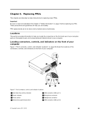
...69 shows the locations of your computer. Chapter 8. Important Be sure to help you locate the connectors on the front and rear of your computer, parts on the front of the connectors, controls, and indicators on the system board, and components and internal drives in your computer. Front connector, control,... 2 Power indicator 3 Power switch 4 Optical drive eject/close button 5 USB connector (USB port 1) 6 Microphone connector 7 Headphone connector 8 USB connector (USB port 2) © Copyright Lenovo 2011, 2012 69 These precautions and guidelines will help you work safely.
...69 shows the locations of your computer. Chapter 8. Important Be sure to help you locate the connectors on the front and rear of your computer, parts on the front of the connectors, controls, and indicators on the system board, and components and internal drives in your computer. Front connector, control,... 2 Power indicator 3 Power switch 4 Optical drive eject/close button 5 USB connector (USB port 1) 6 Microphone connector 7 Headphone connector 8 USB connector (USB port 2) © Copyright Lenovo 2011, 2012 69 These precautions and guidelines will help you work safely.
Hardware Maintenance Manual
Page 77
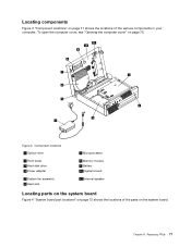
Locating components Figure 3 "Component locations" on page 71 shows the locations of the parts on the system board. Component locations 1 Optical drive 2 Front bezel 3 Hard disk drive 4 Power adapter 5 System fan assembly 6 Heat sink 7 Microprocessor 8 Memory module 9 Battery 10 System board 11 Internal speaker Locating parts on the system board Figure 4 "System board part locations" on page 72. Chapter 8. Figure 3. To open the computer cover, see "Opening the computer cover" on page 72 shows the locations of the various components in your computer. Replacing FRUs 71
Locating components Figure 3 "Component locations" on page 71 shows the locations of the parts on the system board. Component locations 1 Optical drive 2 Front bezel 3 Hard disk drive 4 Power adapter 5 System fan assembly 6 Heat sink 7 Microprocessor 8 Memory module 9 Battery 10 System board 11 Internal speaker Locating parts on the system board Figure 4 "System board part locations" on page 72. Chapter 8. Figure 3. To open the computer cover, see "Opening the computer cover" on page 72 shows the locations of the various components in your computer. Replacing FRUs 71

Hardware Maintenance Manual
Page 78
..., go to: http://www.lenovo.com/ThinkCentreUserGuides This section provides instructions on the front bezel) 15 SATA connector 1 (SATA 3.0 connector) 16 System fan connector 17 4-pin power connector 18 Microprocessor Opening the computer cover Attention: Do not open the computer cover. 72 ThinkCentre Hardware Maintenance Manual System board part locations 1 Thermal sensor connector..., and microphone and headphone connectors on how to open your computer or attempt any repair before reading and understanding the "Important safety information" in the ThinkCentre User Guide.
..., go to: http://www.lenovo.com/ThinkCentreUserGuides This section provides instructions on the front bezel) 15 SATA connector 1 (SATA 3.0 connector) 16 System fan connector 17 4-pin power connector 18 Microprocessor Opening the computer cover Attention: Do not open the computer cover. 72 ThinkCentre Hardware Maintenance Manual System board part locations 1 Thermal sensor connector..., and microphone and headphone connectors on how to open your computer or attempt any repair before reading and understanding the "Important safety information" in the ThinkCentre User Guide.
Hardware Maintenance Manual
Page 80
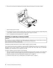
... align the plastic tabs on the bottom of the ThinkCentre User Guide, go to "Completing the parts replacement" on page 72. 3. Go to : http://www.lenovo.com/ThinkCentreUserGuides This section provides instructions on page 71. 74 ThinkCentre Hardware Maintenance Manual Installing or replacing a memory module Attention...replace a memory module. To obtain a copy of the bezel with the corresponding holes in the ThinkCentre User Guide. To install or replace a memory module, do the following: 1. See "Locating parts on the system board" on how to a maximum of 16 GB. Figure 6. When installing...
... align the plastic tabs on the bottom of the ThinkCentre User Guide, go to "Completing the parts replacement" on page 72. 3. Go to : http://www.lenovo.com/ThinkCentreUserGuides This section provides instructions on page 71. 74 ThinkCentre Hardware Maintenance Manual Installing or replacing a memory module Attention...replace a memory module. To obtain a copy of the bezel with the corresponding holes in the ThinkCentre User Guide. To install or replace a memory module, do the following: 1. See "Locating parts on the system board" on how to a maximum of 16 GB. Figure 6. When installing...
Hardware Maintenance Manual
Page 81
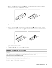
... card, do the following: Chapter 8. Replacing FRUs 75 Make sure that the memory module is secured in the ThinkCentre User Guide. Figure 8. Go to "Completing the parts replacement" on how to : http://www.lenovo.com/ThinkCentreUserGuides This section provides instructions on page 98. To obtain a copy of the new memory module into place... the memory module firmly and pivot the memory module until it snaps into the slot 1 . Open the retaining clips. Insert the notched end 2 of the ThinkCentre User Guide, go to replace a PCI card.
... card, do the following: Chapter 8. Replacing FRUs 75 Make sure that the memory module is secured in the ThinkCentre User Guide. Figure 8. Go to "Completing the parts replacement" on how to : http://www.lenovo.com/ThinkCentreUserGuides This section provides instructions on page 98. To obtain a copy of the new memory module into place... the memory module firmly and pivot the memory module until it snaps into the slot 1 . Open the retaining clips. Insert the notched end 2 of the ThinkCentre User Guide, go to replace a PCI card.
Hardware Maintenance Manual
Page 82
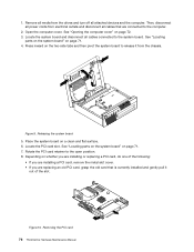
...Then, disconnect all power cords from electrical outlets and disconnect all media from the chassis. Figure 9. Releasing the system board 5. See "Locating parts on the system board" on whether you are replacing an old PCI card, grasp the old card that are installing or replacing a PCI... to the computer. 2. 1. Locate the PCI card slot. See "Locating parts on the system board" on page 72. 3. Rotate the PCI card retainer to the system board. Removing the PCI card 76 ThinkCentre Hardware Maintenance Manual See "Opening the computer cover" on page 71. 4. Locate...
...Then, disconnect all power cords from electrical outlets and disconnect all media from the chassis. Figure 9. Releasing the system board 5. See "Locating parts on the system board" on whether you are replacing an old PCI card, grasp the old card that are installing or replacing a PCI... to the computer. 2. 1. Locate the PCI card slot. See "Locating parts on the system board" on page 72. 3. Rotate the PCI card retainer to the system board. Removing the PCI card 76 ThinkCentre Hardware Maintenance Manual See "Opening the computer cover" on page 71. 4. Locate...


