Hardware Maintenance Manual
Page 1
ThinkCentre Hardware Maintenance Manual Machine Types: 4466, 4468, 4471, 4473, 4474, 4476, 4477, 4479, 4480, 4485, 4495, 4496, 4497, 4498, 4499, 4503, 4504, 4512, 4513, 4514, 4517, 4518, 4524, 4554, 7005, 7021, 7023, 7032, 7033, 7034, 7035, 7049, 7052, 7053, 7072, 7073, 7079, 7136, 7177, and 7178
ThinkCentre Hardware Maintenance Manual Machine Types: 4466, 4468, 4471, 4473, 4474, 4476, 4477, 4479, 4480, 4485, 4495, 4496, 4497, 4498, 4499, 4503, 4504, 4512, 4513, 4514, 4517, 4518, 4524, 4554, 7005, 7021, 7023, 7032, 7033, 7034, 7035, 7049, 7052, 7053, 7072, 7073, 7079, 7136, 7177, and 7178
Hardware Maintenance Manual
Page 3
ThinkCentre Hardware Maintenance Manual Machine Types: 4466, 4468, 4471, 4473, 4474, 4476, 4477, 4479, 4480, 4485, 4495, 4496, 4497, 4498, 4499, 4503, 4504, 4512, 4513, 4514, 4517, 4518, 4524, 4554, 7005, 7021, 7023, 7032, 7033, 7034, 7035, 7049, 7052, 7053, 7072, 7073, 7079, 7136, 7177, and 7178
ThinkCentre Hardware Maintenance Manual Machine Types: 4466, 4468, 4471, 4473, 4474, 4476, 4477, 4479, 4480, 4485, 4495, 4496, 4497, 4498, 4499, 4503, 4504, 4512, 4513, 4514, 4517, 4518, 4524, 4554, 7005, 7021, 7023, 7032, 7033, 7034, 7035, 7049, 7052, 7053, 7072, 7073, 7079, 7136, 7177, and 7178
Hardware Maintenance Manual
Page 5
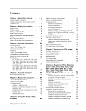
... 71 Chapter 8. General information . . . . 33 Lenovo Welcome 33 Lenovo ThinkVantage Tools 33 Lenovo Solution Center 33 SimpleTap 33 Lenovo ThinkVantage Toolbox 33 ThinkVantage Productivity Center 34 Additional information resources ...34 Specifications 34 For machine types: 4468, 4473, 4476, 4479, 4495, 4497, 4499, 4504, 4513, 4517, 4524, 7021, 7032, 7034, 7049, 7052, 7053, 7073, 7136, and 7178 34 For machine types: 4466, 4471, 4474, 4477, 4480...
... 71 Chapter 8. General information . . . . 33 Lenovo Welcome 33 Lenovo ThinkVantage Tools 33 Lenovo Solution Center 33 SimpleTap 33 Lenovo ThinkVantage Toolbox 33 ThinkVantage Productivity Center 34 Additional information resources ...34 Specifications 34 For machine types: 4468, 4473, 4476, 4479, 4495, 4497, 4499, 4504, 4513, 4517, 4524, 7021, 7032, 7034, 7049, 7052, 7053, 7073, 7136, and 7178 34 For machine types: 4466, 4471, 4474, 4477, 4480...
Hardware Maintenance Manual
Page 6
... 32 Recovery CD 296 Windows Vista Business 32 Recovery CD . . 298 Windows Vista Home Basic 32 Recovery CD 299 Overall: MT 4466, 4471, 4474, 4477, 4480, 4485, 4496, 4498, 4503, 4512, 4514, 4518, 4554, 7005, 7023, 7033, 7035, 7072, 7079, and 7177 . . . . 301 Mechanical FRUs 326 Keyboard ...Windows Vista Business 32 Recovery CD . . 471 Windows Vista Home Basic 32 Recovery CD 472 Chapter 11. Replacing FRUs (Machine Types: 4466, 4471, 4474, 4477, 4480, 4485, 4496, 4498, 4503, 4512, 4514, 4518, 4554, 7005, 7023, 7033, 7035, 7072, 7079, and 7177 115 Locations 115 Locating connectors, controls,...
... 32 Recovery CD 296 Windows Vista Business 32 Recovery CD . . 298 Windows Vista Home Basic 32 Recovery CD 299 Overall: MT 4466, 4471, 4474, 4477, 4480, 4485, 4496, 4498, 4503, 4512, 4514, 4518, 4554, 7005, 7023, 7033, 7035, 7072, 7079, and 7177 . . . . 301 Mechanical FRUs 326 Keyboard ...Windows Vista Business 32 Recovery CD . . 471 Windows Vista Home Basic 32 Recovery CD 472 Chapter 11. Replacing FRUs (Machine Types: 4466, 4471, 4474, 4477, 4480, 4485, 4496, 4498, 4503, 4512, 4514, 4518, 4554, 7005, 7023, 7033, 7035, 7072, 7079, and 7177 115 Locations 115 Locating connectors, controls,...
Hardware Maintenance Manual
Page 43
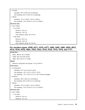
... to 10 000 ft (-15.2 to 3 048 m) Non-operating: -50 to 35 000 ft (-15.2 to 60 Hz For machine types: 4466, 4471, 4474, 4477, 4480, 4485, 4496, 4498, 4503, 4512, 4514, 4518, 4554, 7005, 7023, 7033, 7035, 7072, 7079, and 7177. Low range: Minimum: 100 V ac Maximum: 127 V ac Input...
... to 10 000 ft (-15.2 to 3 048 m) Non-operating: -50 to 35 000 ft (-15.2 to 60 Hz For machine types: 4466, 4471, 4474, 4477, 4480, 4485, 4496, 4498, 4503, 4512, 4514, 4518, 4554, 7005, 7023, 7033, 7035, 7072, 7079, and 7177. Low range: Minimum: 100 V ac Maximum: 127 V ac Input...
Hardware Maintenance Manual
Page 53
... be accessed. Move the Clear CMOS /Recovery jumper back to the maintenance position (pin 2 and pin 3). 5. For machine types: 4466, 4471, 4474, 4477, 4480, 4485, 4496, 4498, 4503, 4512, 4514, 4518, 4554, 7005, 7023, 7033, 7035, 7072, 7079, and 7177, to open the computer cover, see...Completing the parts replacement" on page 113 Enabling or disabling a device This section provides information on page 44. For machine types: 4466, 4471, 4474, 4477, 4480, 4485, 4496, 4498, 4503, 4512, 4514, 4518, 4554, 7005, 7023, 7033, 7035, 7072, 7079, and 7177, see "Completing the parts replacement...
... be accessed. Move the Clear CMOS /Recovery jumper back to the maintenance position (pin 2 and pin 3). 5. For machine types: 4466, 4471, 4474, 4477, 4480, 4485, 4496, 4498, 4503, 4512, 4514, 4518, 4554, 7005, 7023, 7033, 7035, 7072, 7079, and 7177, to open the computer cover, see...Completing the parts replacement" on page 113 Enabling or disabling a device This section provides information on page 44. For machine types: 4466, 4471, 4474, 4477, 4480, 4485, 4496, 4498, 4503, 4512, 4514, 4518, 4554, 7005, 7023, 7033, 7035, 7072, 7079, and 7177, see "Completing the parts replacement...
Hardware Maintenance Manual
Page 123
...in your computer connectors, components, parts on page 3 before you locate your computer might look slightly different from the illustrations. © Copyright Lenovo 2011, 2012 115 Chapter 9. FRU replacements are documented. Only the major FRUs are to be done only by trained service technicians. Locations ...and internal drives. This chapter does not contain the remove or replace procedure for all FRUs. Replacing FRUs (Machine Types: 4466, 4471, 4474, 4477, 4480, 4485, 4496, 4498, 4503, 4512, 4514, 4518, 4554, 7005, 7023, 7033, 7035, 7072, 7079, and 7177.) Important: Be sure to...
...in your computer connectors, components, parts on page 3 before you locate your computer might look slightly different from the illustrations. © Copyright Lenovo 2011, 2012 115 Chapter 9. FRU replacements are documented. Only the major FRUs are to be done only by trained service technicians. Locations ...and internal drives. This chapter does not contain the remove or replace procedure for all FRUs. Replacing FRUs (Machine Types: 4466, 4471, 4474, 4477, 4480, 4485, 4496, 4498, 4503, 4512, 4514, 4518, 4554, 7005, 7023, 7033, 7035, 7072, 7079, and 7177.) Important: Be sure to...
Hardware Maintenance Manual
Page 125
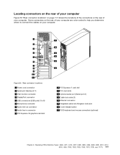
Figure 50. Replacing FRUs (Machine Types: 4466, 4471, 4474, 4477, 4480, 4485, 4496, 4498, 4503, 4512, 4514, 4518, 4554, 7005, 7023, 7033, 7035, 7072, 7079, and 7177.) 117 Rear connector locations 1 Power cord connector 2 Serial port (...
Figure 50. Replacing FRUs (Machine Types: 4466, 4471, 4474, 4477, 4480, 4485, 4496, 4498, 4503, 4512, 4514, 4518, 4554, 7005, 7023, 7033, 7035, 7072, 7079, and 7177.) 117 Rear connector locations 1 Power cord connector 2 Serial port (...
Hardware Maintenance Manual
Page 127
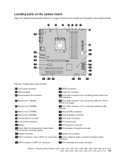
... bezel) 5 Memory slot 2 (DIMM2) 19 Front USB connector 2 (for connecting USB port 1and 2 on the system board. Replacing FRUs (Machine Types: 4466, 4471, 4474, 4477, 4480, 4485, 4496, 4498, 4503, 4512, 4514, 4518, 4554, 7005, 7023, 7033, 7035, 7072, 7079, and 7177.) 119
... bezel) 5 Memory slot 2 (DIMM2) 19 Front USB connector 2 (for connecting USB port 1and 2 on the system board. Replacing FRUs (Machine Types: 4466, 4471, 4474, 4477, 4480, 4485, 4496, 4498, 4503, 4512, 4514, 4518, 4554, 7005, 7023, 7033, 7035, 7072, 7079, and 7177.) 119

Hardware Maintenance Manual
Page 129
...from the package and your computer" on page 74 and "Locating connectors on the rear of the ThinkCentre User Guide, go to: http://www.lenovo.com/ThinkCentreUserGuides This section provides instructions on any repair before reading and understanding the "Important safety information"...the ThinkCentre User Guide. Chapter 9. Disconnect the power cords, Input/Output cables, and any locking device that are connected to do the following: 1. Handle PCI cards, memory modules, system boards, and microprocessors by Lenovo. 2. Replacing FRUs (Machine Types: 4466, 4471, 4474, 4477, 4480, ...
...from the package and your computer" on page 74 and "Locating connectors on the rear of the ThinkCentre User Guide, go to: http://www.lenovo.com/ThinkCentreUserGuides This section provides instructions on any repair before reading and understanding the "Important safety information"...the ThinkCentre User Guide. Chapter 9. Disconnect the power cords, Input/Output cables, and any locking device that are connected to do the following: 1. Handle PCI cards, memory modules, system boards, and microprocessors by Lenovo. 2. Replacing FRUs (Machine Types: 4466, 4471, 4474, 4477, 4480, ...
Hardware Maintenance Manual
Page 131
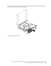
Removing the front bezel Chapter 9. Replacing FRUs (Machine Types: 4466, 4471, 4474, 4477, 4480, 4485, 4496, 4498, 4503, 4512, 4514, 4518, 4554, 7005, 7023, 7033, 7035, 7072, 7079, and 7177.) 123 Remove the front bezel by releasing the three plastic tabs on the top of the front bezel and pivoting the front bezel outward to remove it from the computer. 3. Figure 55.
Removing the front bezel Chapter 9. Replacing FRUs (Machine Types: 4466, 4471, 4474, 4477, 4480, 4485, 4496, 4498, 4503, 4512, 4514, 4518, 4554, 7005, 7023, 7033, 7035, 7072, 7079, and 7177.) 123 Remove the front bezel by releasing the three plastic tabs on the top of the front bezel and pivoting the front bezel outward to remove it from the computer. 3. Figure 55.
Hardware Maintenance Manual
Page 133
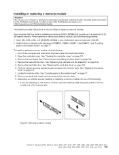
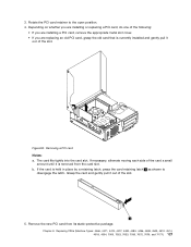
... copy of the ThinkCentre User Guide, go to install or replace a memory module. See "Opening the computer cover" on how to : http://www.lenovo.com/ThinkCentreUserGuides This section provides instructions on page 121. 3. Remove the front bezel. Replacing FRUs (Machine Types: 4466, 4471, 4474, 4477, 4480, 4485, 4496, ... module, open your computer or attempt any combination up to a maximum of 32 GB. • Install memory modules in the ThinkCentre User Guide. Your computer has four slots for installing or replacing DDR3 UDIMMs that might prevent access to the memory slots. See ...
... copy of the ThinkCentre User Guide, go to install or replace a memory module. See "Opening the computer cover" on how to : http://www.lenovo.com/ThinkCentreUserGuides This section provides instructions on page 121. 3. Remove the front bezel. Replacing FRUs (Machine Types: 4466, 4471, 4474, 4477, 4480, 4485, 4496, ... module, open your computer or attempt any combination up to a maximum of 32 GB. • Install memory modules in the ThinkCentre User Guide. Your computer has four slots for installing or replacing DDR3 UDIMMs that might prevent access to the memory slots. See ...
Hardware Maintenance Manual
Page 135
... held in place by a retaining latch, press the card retaining latch 1 as shown to the open position. 4. Replacing FRUs (Machine Types: 4466, 4471, 4474, 4477, 4480, 4485, 4496, 4498, 4503, 4512, 4514, 4518, 4554, 7005, 7023, 7033, 7035, 7072, 7079, and 7177.) 127
... held in place by a retaining latch, press the card retaining latch 1 as shown to the open position. 4. Replacing FRUs (Machine Types: 4466, 4471, 4474, 4477, 4480, 4485, 4496, 4498, 4503, 4512, 4514, 4518, 4554, 7005, 7023, 7033, 7035, 7072, 7079, and 7177.) 127
Hardware Maintenance Manual
Page 137
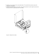
Then install the two screws to secure the card reader to align the screw hole in the bracket with the corresponding hole in the chassis. Figure 62. Then push the bracket to the left to the bracket. 6. Install the card reader bracket to the chassis. Replacing FRUs (Machine Types: 4466, 4471, 4474, 4477, 4480, 4485, 4496, 4498, 4503, 4512, 4514, 4518, 4554, 7005, 7023, 7033, 7035, 7072, 7079, and 7177.) 129 5. Install the new card reader into the card reader bracket. Installing the card reader Chapter 9.
Then install the two screws to secure the card reader to align the screw hole in the bracket with the corresponding hole in the chassis. Figure 62. Then push the bracket to the left to the bracket. 6. Install the card reader bracket to the chassis. Replacing FRUs (Machine Types: 4466, 4471, 4474, 4477, 4480, 4485, 4496, 4498, 4503, 4512, 4514, 4518, 4554, 7005, 7023, 7033, 7035, 7072, 7079, and 7177.) 129 5. Install the new card reader into the card reader bracket. Installing the card reader Chapter 9.
Hardware Maintenance Manual
Page 139
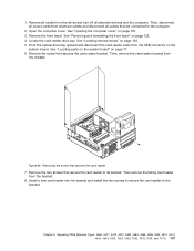
... that secure the card reader to its bracket. Then remove the failing card reader from the chassis. Replacing FRUs (Machine Types: 4466, 4471, 4474, 4477, 4480, 4485, 4496, 4498, 4503, 4512, 4514, 4518, 4554, 7005, 7023, 7033, 7035, 7072, 7079, and 7177.) 131 Then, disconnect all power cords from electrical outlets...
... that secure the card reader to its bracket. Then remove the failing card reader from the chassis. Replacing FRUs (Machine Types: 4466, 4471, 4474, 4477, 4480, 4485, 4496, 4498, 4503, 4512, 4514, 4518, 4554, 7005, 7023, 7033, 7035, 7072, 7079, and 7177.) 131 Then, disconnect all power cords from electrical outlets...
Hardware Maintenance Manual
Page 141
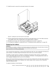
... "Important safety information" in features. The battery keeps this information active when you turn off the computer. Replacing FRUs (Machine Types: 4466, 4471, 4474, 4477, 4480, 4485, 4496, 4498, 4503, 4512, 4514, 4518, 4554, 7005, 7023, 7033, 7035, 7072, 7079, and 7177.) 133 See "Removing and reinstalling the front bezel...Figure 67. To complete the installation or replacement, go to the chassis. 10. Install the screw to secure the card reader bracket to : http://www.lenovo.com/ThinkCentreUserGuides Your computer has a special type of the ThinkCentre Safety and Warranty Guide.
... "Important safety information" in features. The battery keeps this information active when you turn off the computer. Replacing FRUs (Machine Types: 4466, 4471, 4474, 4477, 4480, 4485, 4496, 4498, 4503, 4512, 4514, 4518, 4554, 7005, 7023, 7033, 7035, 7072, 7079, and 7177.) 133 See "Removing and reinstalling the front bezel...Figure 67. To complete the installation or replacement, go to the chassis. 10. Install the screw to secure the card reader bracket to : http://www.lenovo.com/ThinkCentreUserGuides Your computer has a special type of the ThinkCentre Safety and Warranty Guide.
Hardware Maintenance Manual
Page 143
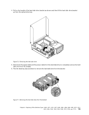
... the retaining clips as shown and then lift the hard disk drive bracket up from the chassis. 6. Replacing FRUs (Machine Types: 4466, 4471, 4474, 4477, 4480, 4485, 4496, 4498, 4503, 4512, 4514, 4518, 4554, 7005, 7023, 7033, 7035, 7072, 7079, and 7177.) 135 Pull on the handle of the hard disk...
... the retaining clips as shown and then lift the hard disk drive bracket up from the chassis. 6. Replacing FRUs (Machine Types: 4466, 4471, 4474, 4477, 4480, 4485, 4496, 4498, 4503, 4512, 4514, 4518, 4554, 7005, 7023, 7033, 7035, 7072, 7079, and 7177.) 135 Pull on the handle of the hard disk...
Hardware Maintenance Manual
Page 145
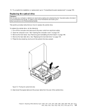
... your computer or attempt any repair before reading and understanding the "Important safety information" in the ThinkCentre User Guide. Open the computer cover. See "Removing and reinstalling the front bezel" on page ...to replace the optical drive. To complete the installation or replacement, go to: http://www.lenovo.com/ThinkCentreUserGuides This section provides instructions on how to pivot the optical drive bay upward. See ...bay 6. Replacing FRUs (Machine Types: 4466, 4471, 4474, 4477, 4480, 4485, 4496, 4498, 4503, 4512, 4514, 4518, 4554, 7005, 7023, 7033, 7035, 7072, 7079...
... your computer or attempt any repair before reading and understanding the "Important safety information" in the ThinkCentre User Guide. Open the computer cover. See "Removing and reinstalling the front bezel" on page ...to replace the optical drive. To complete the installation or replacement, go to: http://www.lenovo.com/ThinkCentreUserGuides This section provides instructions on how to pivot the optical drive bay upward. See ...bay 6. Replacing FRUs (Machine Types: 4466, 4471, 4474, 4477, 4480, 4485, 4496, 4498, 4503, 4512, 4514, 4518, 4554, 7005, 7023, 7033, 7035, 7072, 7079...

Hardware Maintenance Manual
Page 147
... three to five minutes to the computer. 2. Chapter 9. Replacing FRUs (Machine Types: 4466, 4471, 4474, 4477, 4480, 4485, 4496, 4498, 4503, 4512, 4514, 4518, 4554, 7005, 7023, 7033, 7035, 7072, 7079,... the system board. Connect the signal cable and the power cable to the rear of the ThinkCentre User Guide, go to "Completing the parts replacement" on page 160. To complete the installation...fan assembly. See "Locating parts on the system board" on how to : http://www.lenovo.com/ThinkCentreUserGuides This section provides instructions on page 77. Remove all media from electrical outlets ...
... three to five minutes to the computer. 2. Chapter 9. Replacing FRUs (Machine Types: 4466, 4471, 4474, 4477, 4480, 4485, 4496, 4498, 4503, 4512, 4514, 4518, 4554, 7005, 7023, 7033, 7035, 7072, 7079,... the system board. Connect the signal cable and the power cable to the rear of the ThinkCentre User Guide, go to "Completing the parts replacement" on page 160. To complete the installation...fan assembly. See "Locating parts on the system board" on how to : http://www.lenovo.com/ThinkCentreUserGuides This section provides instructions on page 77. Remove all media from electrical outlets ...

Hardware Maintenance Manual
Page 149
.... Connect the new heat sink and fan assembly cable to the microprocessor fan connector on page 140: a. Replacing FRUs (Machine Types: 4466, 4471, 4474, 4477, 4480, 4485, 4496, 4498, 4503, 4512, 4514, 4518, 4554, 7005, 7023, 7033, 7035, 7072, 7079, and 7177.) 141 Removing the heat sink fan duct 7. b. Chapter 9. Partially...
.... Connect the new heat sink and fan assembly cable to the microprocessor fan connector on page 140: a. Replacing FRUs (Machine Types: 4466, 4471, 4474, 4477, 4480, 4485, 4496, 4498, 4503, 4512, 4514, 4518, 4554, 7005, 7023, 7033, 7035, 7072, 7079, and 7177.) 141 Removing the heat sink fan duct 7. b. Chapter 9. Partially...