BIOS Windows Management Instrumentation Interface Deployment Guide
Page 15
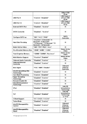
...Seconds", "12 Seconds","15 Seconds","21 Seconds","30 Seconds" "IGD","PCI","PEG","Auto" Pre-Allocated Memory Size "32MB","64MB","128MB" Total Graphics Memory "128MB","256MB","Maximum" Multi-Monitor Support Onboard Audio Controller Onboard Ethernet Controller "Disabled","Enabled" "...Enabled" "Disabled","Enabled" VT-d "Disabled","Enabled" TxT C State Support Turbo Mode Intel(R) Manageability Control Intel(R) Manageability Reset @Copyright Lenovo 2011 "Disabled","Enabled" "C1","C1C3","C1C3C6" "Disabled","Enabled" "Disabled","Enabled" "Disabled","Enabled" &Rear USB Ports USB Support ...
...Seconds", "12 Seconds","15 Seconds","21 Seconds","30 Seconds" "IGD","PCI","PEG","Auto" Pre-Allocated Memory Size "32MB","64MB","128MB" Total Graphics Memory "128MB","256MB","Maximum" Multi-Monitor Support Onboard Audio Controller Onboard Ethernet Controller "Disabled","Enabled" "...Enabled" "Disabled","Enabled" VT-d "Disabled","Enabled" TxT C State Support Turbo Mode Intel(R) Manageability Control Intel(R) Manageability Reset @Copyright Lenovo 2011 "Disabled","Enabled" "C1","C1C3","C1C3C6" "Disabled","Enabled" "Disabled","Enabled" "Disabled","Enabled" &Rear USB Ports USB Support ...
Hardware Maintenance Manual
Page 5
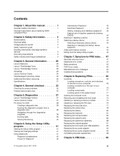
...Additional information resources 30 Specifications 31 Chapter 4. Diagnostics 37 Lenovo ThinkVantage Toolbox 37 Lenovo Solution Center 37 PC-Doctor for power problems 33 Problem determination tips 34 Chapter 5. FRU lists 99 © Copyright Lenovo 2011, 2012 iii About this manual 1 Important safety information...board . . . . 71 Opening the computer cover 72 Removing and reinstalling the front bezel . . . . 73 Installing or replacing a memory module . . . . 74 Installing or replacing the PCI card 75 Replacing the hard disk drive 77 Replacing the optical drive 78 Replacing the...
...Additional information resources 30 Specifications 31 Chapter 4. Diagnostics 37 Lenovo ThinkVantage Toolbox 37 Lenovo Solution Center 37 PC-Doctor for power problems 33 Problem determination tips 34 Chapter 5. FRU lists 99 © Copyright Lenovo 2011, 2012 iii About this manual 1 Important safety information...board . . . . 71 Opening the computer cover 72 Removing and reinstalling the front bezel . . . . 73 Installing or replacing a memory module . . . . 74 Installing or replacing the PCI card 75 Replacing the hard disk drive 77 Replacing the optical drive 78 Replacing the...

Hardware Maintenance Manual
Page 47
... and changing settings The Setup Utility program menu lists various items about the system configuration. The keys used to your computer or the memory module size has decreased, an error message will be displayed until you decide to navigate through BIOS menu choices. Make sure your computer...have to set any passwords to use either the keyboard or the mouse to set any passwords, read the following sections. © Copyright Lenovo 2011, 2012 41 Note: If a Power-On Password or an Administrator Password has been set passwords to prevent unauthorized access to view and...
... and changing settings The Setup Utility program menu lists various items about the system configuration. The keys used to your computer or the memory module size has decreased, an error message will be displayed until you decide to navigate through BIOS menu choices. Make sure your computer...have to set any passwords to use either the keyboard or the mouse to set any passwords, read the following sections. © Copyright Lenovo 2011, 2012 41 Note: If a Power-On Password or an Administrator Password has been set passwords to prevent unauthorized access to view and...
Hardware Maintenance Manual
Page 54
... a disc" on page 186. 2. See "Updating (flashing) the BIOS from a disc" on page 186. 2. See "Updating (flashing) the BIOS from a disc" on page 186. 2. Run memory test 4. Flash the system. See "Updating (flashing) the BIOS from a disc" on page 186. 2. Press F3 to reset the log file. 1. Replace the component that... test to review the log file. 2. See Chapter 6 "Using the Setup Utility program" on page 186. 2. Re-run test. 3. Replace the component under test. 48 ThinkCentre Hardware Maintenance Manual
... a disc" on page 186. 2. See "Updating (flashing) the BIOS from a disc" on page 186. 2. See "Updating (flashing) the BIOS from a disc" on page 186. 2. Run memory test 4. Flash the system. See "Updating (flashing) the BIOS from a disc" on page 186. 2. Press F3 to reset the log file. 1. Replace the component that... test to review the log file. 2. See Chapter 6 "Using the Setup Utility program" on page 186. 2. Re-run test. 3. Replace the component under test. 48 ThinkCentre Hardware Maintenance Manual
Hardware Maintenance Manual
Page 55
... page 186. 2. Symptom-to "Undetermined problems" on page 186. 2. System board Chapter 7. See "Updating (flashing) the BIOS from a disc" on page 186. 2. System board 1. Run memory test 4. Flash the system. Make sure the component that is called out is connected and/or enabled. Go to -FRU index 49 Adapter card 2. Flash...
... page 186. 2. Symptom-to "Undetermined problems" on page 186. 2. System board Chapter 7. See "Updating (flashing) the BIOS from a disc" on page 186. 2. System board 1. Run memory test 4. Flash the system. Make sure the component that is called out is connected and/or enabled. Go to -FRU index 49 Adapter card 2. Flash...
Hardware Maintenance Manual
Page 59
Replace the component under function test. 1. Go to "Undetermined problems" on page 66. 2. Flash the system and re-test. 3. System board No action 1. Run memory test 4. Remove USB device(s) and re-test. 2. System board Information only Restart the test, if necessary. Symptom-to reset the log file. 1. Diagnostic Error Code ...
Replace the component under function test. 1. Go to "Undetermined problems" on page 66. 2. Flash the system and re-test. 3. System board No action 1. Run memory test 4. Remove USB device(s) and re-test. 2. System board Information only Restart the test, if necessary. Symptom-to reset the log file. 1. Diagnostic Error Code ...
Hardware Maintenance Manual
Page 67
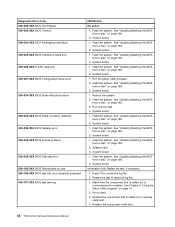
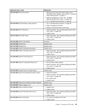
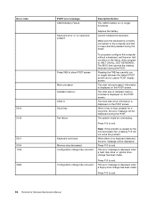
... error 185-000-XXX Asset Security Test Passed 185-XXX-XXX Asset Security failure 185-278-XXX Asset Security Chassis Intrusion 201-000-XXX System Memory Test Passed FRU/Action 1. See "Updating (flashing) the BIOS from a disc" on page 186. 3. Check AC/DC power adapter voltages. 3. Check fans 2. System board Information...
... error 185-000-XXX Asset Security Test Passed 185-XXX-XXX Asset Security failure 185-278-XXX Asset Security Chassis Intrusion 201-000-XXX System Memory Test Passed FRU/Action 1. See "Updating (flashing) the BIOS from a disc" on page 186. 3. Check AC/DC power adapter voltages. 3. Check fans 2. System board Information...
Hardware Maintenance Manual
Page 68
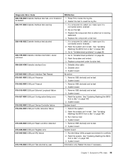
...the Hi-Capacity Cartridge Drive and re-test the system. 1. System board No action Remove the Joystick and re-test the system 62 ThinkCentre Hardware Maintenance Manual System board 3. Check AC/DC power adapter voltages 3. Hard Disk drive (IDE) 5. System board 1. Check and test... Keyboard 3. System board No action 1. Reseat the hard disk drive cable 4. System board No action 1. Replace the memory module called out by the test 2. Diskette Drive Cable 2. Mouse 2. Check AC/DC power adapter voltages 3. SCSI adapter card 6. Check and ...
...the Hi-Capacity Cartridge Drive and re-test the system. 1. System board No action Remove the Joystick and re-test the system 62 ThinkCentre Hardware Maintenance Manual System board 3. Check AC/DC power adapter voltages 3. Hard Disk drive (IDE) 5. System board 1. Check and test... Keyboard 3. System board No action 1. Reseat the hard disk drive cable 4. System board No action 1. Replace the memory module called out by the test 2. Diskette Drive Cable 2. Mouse 2. Check AC/DC power adapter voltages 3. SCSI adapter card 6. Check and ...
Hardware Maintenance Manual
Page 69
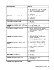
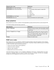
.... Beep Symptom 2 short 1 long beeps 4, 5, 6, or 7 beeps9, 10, or 11 beeps 8 beeps FRU/Action Reseat the memory modules. If the error persists, replace the memory modules one at a time until the failing adapter is determined. Cable 3. POST error codes Each time you turn on your computer, it...the operation of tests is displayed on the screen. This series of the computer components and some basic system board operations • Checks the memory operation • Starts the video operation • Verifies that the boot drive is working If the POST detects a problem, an error message...
.... Beep Symptom 2 short 1 long beeps 4, 5, 6, or 7 beeps9, 10, or 11 beeps 8 beeps FRU/Action Reseat the memory modules. If the error persists, replace the memory modules one at a time until the failing adapter is determined. Cable 3. POST error codes Each time you turn on your computer, it...the operation of tests is displayed on the screen. This series of the computer components and some basic system board operations • Checks the memory operation • Starts the video operation • Verifies that the boot drive is working If the POST detects a problem, an error message...
Hardware Maintenance Manual
Page 70
...and a custom POST display screen. Pressing the TAB key permits you to exit. Press F10 to exit. The total size of installed memory modules is displayed on the POST screen. When there is displayed when a floppy drive change has been made . Cannot initialize the keyboard....BUT KEYBOARD. To purposely configure the computer without a keyboard, set the error halt condition in the Setup Utility program to exit. 64 ThinkCentre Hardware Maintenance Manual The main microprocessor information is caused by the microprocessor fan, pressing F10 will not solve the problem. The system might...
...and a custom POST display screen. Pressing the TAB key permits you to exit. Press F10 to exit. The total size of installed memory modules is displayed on the POST screen. When there is displayed when a floppy drive change has been made . Cannot initialize the keyboard....BUT KEYBOARD. To purposely configure the computer without a keyboard, set the error halt condition in the Setup Utility program to exit. 64 ThinkCentre Hardware Maintenance Manual The main microprocessor information is caused by the microprocessor fan, pressing F10 will not solve the problem. The system might...
Hardware Maintenance Manual
Page 72
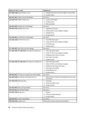
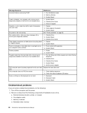
...left to right of characters and color bars 1. Keyboard 2. Remove or disconnect the following : 1. Extended video memory 66 ThinkCentre Hardware Maintenance Manual System Board Power-on indicator or hard disk drive in the first 3.5-inch diskette drive 1. Check...off the computer and the power. 2. Any adapter cards c. Display 2. Check startup sequence 2. Message/Symptom FRU/Action Incorrect memory size during POST 1. Memory Module 3. Keyboard Cable 3. System Board 2. System Board No power or fan not running See "Power problems" on page 33...
...left to right of characters and color bars 1. Keyboard 2. Remove or disconnect the following : 1. Extended video memory 66 ThinkCentre Hardware Maintenance Manual System Board Power-on indicator or hard disk drive in the first 3.5-inch diskette drive 1. Check...off the computer and the power. 2. Any adapter cards c. Display 2. Check startup sequence 2. Message/Symptom FRU/Action Incorrect memory size during POST 1. Memory Module 3. Keyboard Cable 3. System Board 2. System Board No power or fan not running See "Power problems" on page 33...
Hardware Maintenance Manual
Page 77
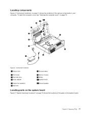
Component locations 1 Optical drive 2 Front bezel 3 Hard disk drive 4 Power adapter 5 System fan assembly 6 Heat sink 7 Microprocessor 8 Memory module 9 Battery 10 System board 11 Internal speaker Locating parts on the system board Figure 4 "System board part locations" on page 72 shows the locations of the various components in your computer. Chapter 8. Replacing FRUs 71 To open the computer cover, see "Opening the computer cover" on the system board. Locating components Figure 3 "Component locations" on page 71 shows the locations of the parts on page 72. Figure 3.
Component locations 1 Optical drive 2 Front bezel 3 Hard disk drive 4 Power adapter 5 System fan assembly 6 Heat sink 7 Microprocessor 8 Memory module 9 Battery 10 System board 11 Internal speaker Locating parts on the system board Figure 4 "System board part locations" on page 72 shows the locations of the various components in your computer. Chapter 8. Replacing FRUs 71 To open the computer cover, see "Opening the computer cover" on the system board. Locating components Figure 3 "Component locations" on page 71 shows the locations of the parts on page 72. Figure 3.

Hardware Maintenance Manual
Page 78
...to open your computer or attempt any repair before reading and understanding the "Important safety information" in the ThinkCentre User Guide. System board part locations 1 Thermal sensor connector 2 Memory slots (2) 3 Battery 4 Microprocessor fan connector 5 Clear CMOS (Complementary Metal Oxide Semiconductor) /Recovery jumper ...2 on the front bezel, LED indicators and power switch, and microphone and headphone connectors on how to : http://www.lenovo.com/ThinkCentreUserGuides This section provides instructions on the front bezel) 15 SATA connector 1 (SATA 3.0 connector) 16 System fan ...
...to open your computer or attempt any repair before reading and understanding the "Important safety information" in the ThinkCentre User Guide. System board part locations 1 Thermal sensor connector 2 Memory slots (2) 3 Battery 4 Microprocessor fan connector 5 Clear CMOS (Complementary Metal Oxide Semiconductor) /Recovery jumper ...2 on the front bezel, LED indicators and power switch, and microphone and headphone connectors on how to : http://www.lenovo.com/ThinkCentreUserGuides This section provides instructions on the front bezel) 15 SATA connector 1 (SATA 3.0 connector) 16 System fan ...
Hardware Maintenance Manual
Page 80
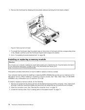
...: http://www.lenovo.com/ThinkCentreUserGuides This section provides instructions on page 98. Remove all media from electrical outlets and disconnect all attached devices and the computer. See "Opening the computer cover" on page 71. 74 ThinkCentre Hardware Maintenance Manual Locate the memory slots. To ...reinstall the front bezel, align the plastic tabs on the bottom of the ThinkCentre User Guide, go to a maximum of 16 GB system memory. Remove the front bezel by releasing the...
...: http://www.lenovo.com/ThinkCentreUserGuides This section provides instructions on page 98. Remove all media from electrical outlets and disconnect all attached devices and the computer. See "Opening the computer cover" on page 71. 74 ThinkCentre Hardware Maintenance Manual Locate the memory slots. To ...reinstall the front bezel, align the plastic tabs on the bottom of the ThinkCentre User Guide, go to a maximum of 16 GB system memory. Remove the front bezel by releasing the...
Hardware Maintenance Manual
Page 81
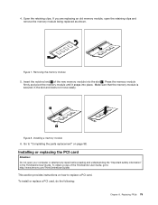
... clips. Go to "Completing the parts replacement" on how to : http://www.lenovo.com/ThinkCentreUserGuides This section provides instructions on page 98. Make sure that the memory module is secured in the ThinkCentre User Guide. Insert the notched end 2 of the ThinkCentre User Guide, go to replace a PCI card. Figure 8. Replacing FRUs 75 4. To...
... clips. Go to "Completing the parts replacement" on how to : http://www.lenovo.com/ThinkCentreUserGuides This section provides instructions on page 98. Make sure that the memory module is secured in the ThinkCentre User Guide. Insert the notched end 2 of the ThinkCentre User Guide, go to replace a PCI card. Figure 8. Replacing FRUs 75 4. To...
Hardware Maintenance Manual
Page 86
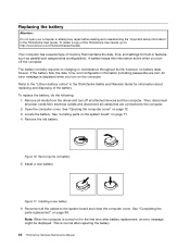
... information about replacing and disposing of the battery. Removing the old battery 5. Open the computer cover. To obtain a copy of memory that are lost. however, no charging or maintenance throughout its life; Figure 17. Then, disconnect all power cords from the drives... the battery fails, the date, time, and configuration information (including passwords) are connected to : http://www.lenovo.com/ThinkCentreUserGuides Your computer has a special type of the ThinkCentre User Guide, go to the computer. 2. Replacing the battery Attention: Do not open your computer or attempt ...
... information about replacing and disposing of the battery. Removing the old battery 5. Open the computer cover. To obtain a copy of memory that are lost. however, no charging or maintenance throughout its life; Figure 17. Then, disconnect all power cords from the drives... the battery fails, the date, time, and configuration information (including passwords) are connected to : http://www.lenovo.com/ThinkCentreUserGuides Your computer has a special type of the ThinkCentre User Guide, go to the computer. 2. Replacing the battery Attention: Do not open your computer or attempt ...
Hardware Maintenance Manual
Page 92
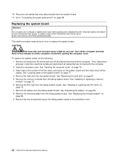
...computer and wait three to five minutes to replace the system board. Take notes of the location of the ThinkCentre User Guide, go to: http://www.lenovo.com/ThinkCentreUserGuides This section provides instructions on page 74. 6. Remove the four screws that secure the failing system... 80. 8. Open the computer cover. See "Installing or replacing a memory module" on how to let the computer cool before reading and understanding the "Important safety information" in the ThinkCentre User Guide. Remove the memory modules from the system board. 17. CAUTION: The heat sink and ...
...computer and wait three to five minutes to replace the system board. Take notes of the location of the ThinkCentre User Guide, go to: http://www.lenovo.com/ThinkCentreUserGuides This section provides instructions on page 74. 6. Remove the four screws that secure the failing system... 80. 8. Open the computer cover. See "Installing or replacing a memory module" on how to let the computer cool before reading and understanding the "Important safety information" in the ThinkCentre User Guide. Remove the memory modules from the system board. 17. CAUTION: The heat sink and ...
Hardware Maintenance Manual
Page 93
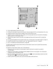
... protect the pins during shipping and handling. Release the lever securing the microprocessor retainer and open the retainer to the protective cover. 13. Install the memory modules, PCI card, battery, and microprocessor that the screw holes are aligned with the mounting studs on page 98. Install one side of the microprocessor...
... protect the pins during shipping and handling. Release the lever securing the microprocessor retainer and open the retainer to the protective cover. 13. Install the memory modules, PCI card, battery, and microprocessor that the screw holes are aligned with the mounting studs on page 98. Install one side of the microprocessor...
Hardware Maintenance Manual
Page 114
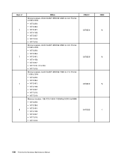
... Q-0 1c FCLGA 1.6GHz 35W • MT 0266: • MT 0384: • MT 2491: • MT 4168: • MT 5067: • MT 7516: • MT 7519: Memory module, 1GB PC3-10600 1333MHz DDR3 SoDIMM • MT 0266: • MT 0384: • MT 2491: • MT 4168: • MT 5067: • MT 7516...
... Q-0 1c FCLGA 1.6GHz 35W • MT 0266: • MT 0384: • MT 2491: • MT 4168: • MT 5067: • MT 7516: • MT 7519: Memory module, 1GB PC3-10600 1333MHz DDR3 SoDIMM • MT 0266: • MT 0384: • MT 2491: • MT 4168: • MT 5067: • MT 7516...
Hardware Maintenance Manual
Page 115
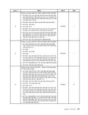
... D4A D4T D5Q D6Q D7Q D8Q D9J E1J E2U E2F E2S E3J E4J FRU # 64Y6651 89Y9225 03T8007 CRU 1 1 N Chapter 9. FRU lists 109 Item # 8 8 10 FRUs Memory module, 2GB PC3-10600 1333MHz DDR3 SoDIMM • MT 0266: A1H A1V A2H A2V A3A A3T A4A A4T B4S B4D B4Y B5S B5D B5Y C8G... C8J C9J D1J D2J D3A D3T D4A D4T D5Q D6Q D9J E1J E3J E4J • MT 7519: A1A A1T A2G A3G A7V A8V B2A B2T Memory module, 4GB PC3-10600 1333MHz DDR3 SoDIMM • MT 0266: B6M B7U B7F B7S B7M B8U B8F B8S B8M C6J C7J D1U D1F D1S D3U...
... D4A D4T D5Q D6Q D7Q D8Q D9J E1J E2U E2F E2S E3J E4J FRU # 64Y6651 89Y9225 03T8007 CRU 1 1 N Chapter 9. FRU lists 109 Item # 8 8 10 FRUs Memory module, 2GB PC3-10600 1333MHz DDR3 SoDIMM • MT 0266: A1H A1V A2H A2V A3A A3T A4A A4T B4S B4D B4Y B5S B5D B5Y C8G... C8J C9J D1J D2J D3A D3T D4A D4T D5Q D6Q D9J E1J E3J E4J • MT 7519: A1A A1T A2G A3G A7V A8V B2A B2T Memory module, 4GB PC3-10600 1333MHz DDR3 SoDIMM • MT 0266: B6M B7U B7F B7S B7M B8U B8F B8S B8M C6J C7J D1U D1F D1S D3U...


