
Hardware Maintenance Manual
Page 121
Replacing FRUs - Ultra SFF Desktop computers 115 Rear connectors The following illustration shows the location of connectors on the rear of the computer. 1 PCI adapter connector 2 Integrated cable lock-latch 3 USB connector 4 USB connector 5 VGA monitor connector 6 Parallel connector 7 Serial connector 8 Ethernet connector 9 USB connectors (2) 10 ESATA connector 11 USB connectors (2) 12 Audio-line-out connector 13 Audio-line-in connector 14 Power supply diagnostic LEDs (some models) 15 Power connector Chapter 9.
Replacing FRUs - Ultra SFF Desktop computers 115 Rear connectors The following illustration shows the location of connectors on the rear of the computer. 1 PCI adapter connector 2 Integrated cable lock-latch 3 USB connector 4 USB connector 5 VGA monitor connector 6 Parallel connector 7 Serial connector 8 Ethernet connector 9 USB connectors (2) 10 ESATA connector 11 USB connectors (2) 12 Audio-line-out connector 13 Audio-line-in connector 14 Power supply diagnostic LEDs (some models) 15 Power connector Chapter 9.
Hardware Maintenance Manual
Page 123
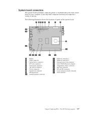
... of devices. Replacing FRUs - System board connectors The system board (sometimes called the planar or motherboard) is the main circuit board in your computer. Ultra SFF Desktop computers 117 It provides basic computer functions and supports a variety of parts on the system board. 1 Battery 2 SATA connector 3 Optical drive connector 4 PCI riser connector...
... of devices. Replacing FRUs - System board connectors The system board (sometimes called the planar or motherboard) is the main circuit board in your computer. Ultra SFF Desktop computers 117 It provides basic computer functions and supports a variety of parts on the system board. 1 Battery 2 SATA connector 3 Optical drive connector 4 PCI riser connector...

Hardware Maintenance Manual
Page 125
Remove any parts that might prevent access to the system board. 3. Pivot the drive bay assembly upward to gain access to the memory connectors. 4. Open the computer cover. See "Opening the cover" on page 118. 2. Replacing FRUs - Ultra SFF Desktop computers 119 Chapter 9. Remove the memory module being replaced by opening the retaining clips as shown. Note: Your computer has support for two memory modules. 1. Replacing a memory module This procedure describes how to remove and replace a memory module.
Remove any parts that might prevent access to the system board. 3. Pivot the drive bay assembly upward to gain access to the memory connectors. 4. Open the computer cover. See "Opening the cover" on page 118. 2. Replacing FRUs - Ultra SFF Desktop computers 119 Chapter 9. Remove the memory module being replaced by opening the retaining clips as shown. Note: Your computer has support for two memory modules. 1. Replacing a memory module This procedure describes how to remove and replace a memory module.

Hardware Maintenance Manual
Page 127
... battery fails, the date, time, and configuration information (including passwords) are lost. Locate the battery. Install the new battery. You might be displayed. Chapter 9. Ultra SFF Desktop computers 121 An error message is displayed when you turn on page 148. Note: When the computer is normal after battery replacement, an error message...
... battery fails, the date, time, and configuration information (including passwords) are lost. Locate the battery. Install the new battery. You might be displayed. Chapter 9. Ultra SFF Desktop computers 121 An error message is displayed when you turn on page 148. Note: When the computer is normal after battery replacement, an error message...
Hardware Maintenance Manual
Page 129
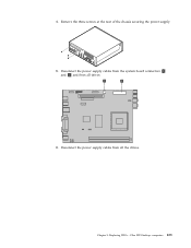
Disconnect the power supply cables from the system board connectors 1 and 2 and from all drives. 6. Disconnect the power supply cables from all the drives. 4. Chapter 9. Replacing FRUs - Remove the three screws at the rear of the chassis securing the power supply. 5. Ultra SFF Desktop computers 123
Disconnect the power supply cables from the system board connectors 1 and 2 and from all drives. 6. Disconnect the power supply cables from all the drives. 4. Chapter 9. Replacing FRUs - Remove the three screws at the rear of the chassis securing the power supply. 5. Ultra SFF Desktop computers 123
Hardware Maintenance Manual
Page 131
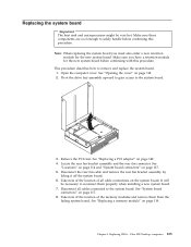
..." on page 114 and "System board connectors" on page 119. See "Replacing a memory module" on page 117. 5. Chapter 9. Replacing FRUs - Remove the PCI riser. Ultra SFF Desktop computers 125 Make sure you must also order a new retention module for the new system board before continuing this procedure. See "Replacing a PCI adapter" on...
..." on page 114 and "System board connectors" on page 119. See "Replacing a memory module" on page 117. 5. Chapter 9. Replacing FRUs - Remove the PCI riser. Ultra SFF Desktop computers 125 Make sure you must also order a new retention module for the new system board before continuing this procedure. See "Replacing a PCI adapter" on...
Hardware Maintenance Manual
Page 133
To remove the microprocessor from the system board socket by lifting it is fully open. 13. Chapter 9. Ultra SFF Desktop computers 127 12. If you must touch the microprocessor, touch only the sides. Replacing FRUs - Remove the microprocessor from the failing system board, release the lever 3 securing the microprocessor 2 then pivot the microprocessor retainer 1 until it out of the microprocessor. Important Do not touch the gold contacts on the bottom of the socket.
To remove the microprocessor from the system board socket by lifting it is fully open. 13. Chapter 9. Ultra SFF Desktop computers 127 12. If you must touch the microprocessor, touch only the sides. Replacing FRUs - Remove the microprocessor from the failing system board, release the lever 3 securing the microprocessor 2 then pivot the microprocessor retainer 1 until it out of the microprocessor. Important Do not touch the gold contacts on the bottom of the socket.
Hardware Maintenance Manual
Page 135
... 1 into position. See "Replacing a memory module" on the microprocessor retainer to the system board. 25. Reinstall the PCI riser. 24. Chapter 9. Replacing FRUs - 17. Ultra SFF Desktop computers 129 Make sure the lever is fully seated. 20.
... 1 into position. See "Replacing a memory module" on the microprocessor retainer to the system board. 25. Reinstall the PCI riser. 24. Chapter 9. Replacing FRUs - 17. Ultra SFF Desktop computers 129 Make sure the lever is fully seated. 20.

Hardware Maintenance Manual
Page 137
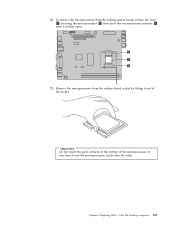
Locate the microprocessor fan connector on page 117. 4. Release the lever 3 securing the microprocessor 2 then pivot the microprocessor retainer 1 until it is fully in the up position. Replacing FRUs - See "System board connectors" on the system board. 3. Ultra SFF Desktop computers 131 Disconnect the microprocessor fan cable from the system board by pivoting the lever 2 securing the heat sink until it is fully open. Lift the heat sink off of the system board. 6. Remove the heat sink 1 from the system board. 5. Chapter 9.
Locate the microprocessor fan connector on page 117. 4. Release the lever 3 securing the microprocessor 2 then pivot the microprocessor retainer 1 until it is fully in the up position. Replacing FRUs - See "System board connectors" on the system board. 3. Ultra SFF Desktop computers 131 Disconnect the microprocessor fan cable from the system board by pivoting the lever 2 securing the heat sink until it is fully open. Lift the heat sink off of the system board. 6. Remove the heat sink 1 from the system board. 5. Chapter 9.

Hardware Maintenance Manual
Page 139
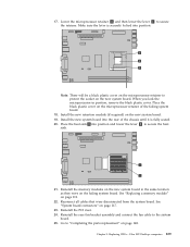
Important To avoid damaging the microprocessor contacts, do not remove it into the socket. Replacing FRUs - Place the black cover on the microprocessor are aligned with the tabs in the microprocessor socket. Position the microprocessor so that protects the gold contacts on the microprocessor 1 , but do not tilt the microprocessor when installing it . Chapter 9. Ultra SFF Desktop computers 133 Loosen the black cover 2 that the notches on the old microprocessor. 10. Pick up the new microprocessor then completely remove the black cover. 9.
Important To avoid damaging the microprocessor contacts, do not remove it into the socket. Replacing FRUs - Place the black cover on the microprocessor are aligned with the tabs in the microprocessor socket. Position the microprocessor so that protects the gold contacts on the microprocessor 1 , but do not tilt the microprocessor when installing it . Chapter 9. Ultra SFF Desktop computers 133 Loosen the black cover 2 that the notches on the old microprocessor. 10. Pick up the new microprocessor then completely remove the black cover. 9.
Hardware Maintenance Manual
Page 141
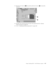
Replacing FRUs - 13. Reconnect the microprocessor fan cable to "Completing the parts replacement" on page 117. 15. Chapter 9. See "System board connectors" on page 148. Go to the system board. Place the new heat sink 1 into position and lower the lever 2 to secure the heat sink. 14. Ultra SFF Desktop computers 135
Replacing FRUs - 13. Reconnect the microprocessor fan cable to "Completing the parts replacement" on page 117. 15. Chapter 9. See "System board connectors" on page 148. Go to the system board. Place the new heat sink 1 into position and lower the lever 2 to secure the heat sink. 14. Ultra SFF Desktop computers 135
Hardware Maintenance Manual
Page 143
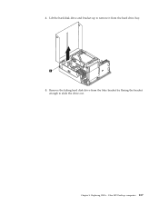
Replacing FRUs - Lift the hard disk drive and bracket up to remove it from the blue bracket by flexing the bracket enough to slide the drive out. 4. Chapter 9. Remove the failing hard disk drive from the hard drive bay. 5. Ultra SFF Desktop computers 137
Replacing FRUs - Lift the hard disk drive and bracket up to remove it from the blue bracket by flexing the bracket enough to slide the drive out. 4. Chapter 9. Remove the failing hard disk drive from the hard drive bay. 5. Ultra SFF Desktop computers 137
Hardware Maintenance Manual
Page 145
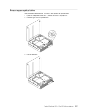
See "Opening the cover" on page 118. 2. Open the computer cover. Chapter 9. Push the optical drive eject button. 3. Pull the eject bar. Replacing FRUs - Ultra SFF Desktop computers 139 Replacing an optical drive This procedure describes how to remove and replace the optical drive. 1.
See "Opening the cover" on page 118. 2. Open the computer cover. Chapter 9. Push the optical drive eject button. 3. Pull the eject bar. Replacing FRUs - Ultra SFF Desktop computers 139 Replacing an optical drive This procedure describes how to remove and replace the optical drive. 1.
Hardware Maintenance Manual
Page 147
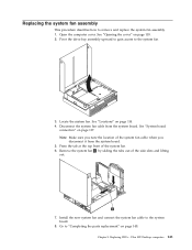
... system board. Remove the system fan 1 by sliding the tabs out of the system fan. 6. Go to remove and replace the system fan assembly. 1. Ultra SFF Desktop computers 141 See "Opening the cover" on page 148. Replacing FRUs - Locate the system fan. Disconnect the system fan cable from the system board. 5. Chapter...
... system board. Remove the system fan 1 by sliding the tabs out of the system fan. 6. Go to remove and replace the system fan assembly. 1. Ultra SFF Desktop computers 141 See "Opening the cover" on page 148. Replacing FRUs - Locate the system fan. Disconnect the system fan cable from the system board. 5. Chapter...
Hardware Maintenance Manual
Page 149
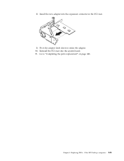
Pivot the adapter latch down to "Completing the parts replacement" on page 148. Install the new adapter into the system board. 11. Reinstall the PCI riser into the expansion connector in the PCI riser. 9. Chapter 9. Ultra SFF Desktop computers 143 8. Go to retain the adapter. 10. Replacing FRUs -
Pivot the adapter latch down to "Completing the parts replacement" on page 148. Install the new adapter into the system board. 11. Reinstall the PCI riser into the expansion connector in the PCI riser. 9. Chapter 9. Ultra SFF Desktop computers 143 8. Go to retain the adapter. 10. Replacing FRUs -
Hardware Maintenance Manual
Page 151
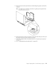
Replacing FRUs - Ultra SFF Desktop computers 145 Connect the speaker cable to "Completing the parts replacement" on page 148. 5. Position the bottom of the new speaker into position. 7. See "System board connectors" on the metal tab shown while lifting the speaker out from the metal tabs that secure it snaps into the metal tabs then pivot the top of the speaker downward until it . 6. Go to the system board. Note: You might need a flat-blade screwdriver to gently pry the speaker from the computer. Chapter 9. Push downward on page 117. 8.
Replacing FRUs - Ultra SFF Desktop computers 145 Connect the speaker cable to "Completing the parts replacement" on page 148. 5. Position the bottom of the new speaker into position. 7. See "System board connectors" on the metal tab shown while lifting the speaker out from the metal tabs that secure it snaps into the metal tabs then pivot the top of the speaker downward until it . 6. Go to the system board. Note: You might need a flat-blade screwdriver to gently pry the speaker from the computer. Chapter 9. Push downward on page 117. 8.
Hardware Maintenance Manual
Page 153
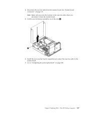
Lift the rear fan bracket assembly out of the rear fan cable when you disconnect it from the system board. Go to the system board. 7. Replacing FRUs - Ultra SFF Desktop computers 147 Chapter 9. Disconnect the rear fan cable from the system board. 5. Note: Make sure you note the location of the slots 1 . 6. 4. Install the new rear fan bracket assembly and connect the rear fan cable to "Completing the parts replacement" on page 117. See "System board connectors" on page 148.
Lift the rear fan bracket assembly out of the rear fan cable when you disconnect it from the system board. Go to the system board. 7. Replacing FRUs - Ultra SFF Desktop computers 147 Chapter 9. Disconnect the rear fan cable from the system board. 5. Note: Make sure you note the location of the slots 1 . 6. 4. Install the new rear fan bracket assembly and connect the rear fan cable to "Completing the parts replacement" on page 117. See "System board connectors" on page 148.


