Hardware Maintenance Manual
Page 5
...53 © Lenovo 2005, 2008. Replacing FRUs (Types 6062, 6065, 6071, 6076, 6089, 9011, 9014, 9071, 9089, 9162, 9182, and 9303 113 Locations 114 Front connectors 114 Rear connectors 115 Computer components 116 System board connectors 117 Opening the cover 118 Replacing a memory module 119 ...board connectors 87 Opening the cover 88 Accessing system board components and drives . . 89 Replacing an adapter card 90 Replacing a memory module 91 Replacing the battery 93 Replacing the power supply 94 Replacing the system board 97 Replacing the microprocessor 100 Replacing the hard...
...53 © Lenovo 2005, 2008. Replacing FRUs (Types 6062, 6065, 6071, 6076, 6089, 9011, 9014, 9071, 9089, 9162, 9182, and 9303 113 Locations 114 Front connectors 114 Rear connectors 115 Computer components 116 System board connectors 117 Opening the cover 118 Replacing a memory module 119 ...board connectors 87 Opening the cover 88 Accessing system board components and drives . . 89 Replacing an adapter card 90 Replacing a memory module 91 Replacing the battery 93 Replacing the power supply 94 Replacing the system board 97 Replacing the microprocessor 100 Replacing the hard...

Hardware Maintenance Manual
Page 60
... No action 1. Flash the system. Flash the system. Run Setup 2. Flash the system. Flash the system. System board 1. Flash the system. Flash the system. Run memory test 4. See "Running tests" on page 494 3. Flash the system. See "Updating (flashing) BIOS from a CD-ROM or diskette" on page 45 for the specific...
... No action 1. Flash the system. Flash the system. Run Setup 2. Flash the system. Flash the system. System board 1. Flash the system. Flash the system. Run memory test 4. See "Running tests" on page 494 3. Flash the system. See "Updating (flashing) BIOS from a CD-ROM or diskette" on page 45 for the specific...

Hardware Maintenance Manual
Page 62
... Flash the system. System board System board System board 1. Power-off /on page 494 2. System board 1. Re-start the test, if necessary 1. System board 1. Run memory test 4. Flash the system. See "Updating (flashing) BIOS from a CD-ROM or diskette" on system and re-test 2. Diagnostic Error Code 001-024-XXX System...
... Flash the system. System board System board System board 1. Power-off /on page 494 2. System board 1. Re-start the test, if necessary 1. System board 1. Run memory test 4. Flash the system. See "Updating (flashing) BIOS from a CD-ROM or diskette" on system and re-test 2. Diagnostic Error Code 001-024-XXX System...

Hardware Maintenance Manual
Page 69
...-to "Undetermined problems" on page 494 3. Flash the system and re-test. Flash the system and re-test. Flash the system and re-test. Run memory test 4. System board Information only Re-start the test, if necessary Chapter 7. Remove USB device(s) and re-test 2. System board System board 1. See "Updating (flashing...
...-to "Undetermined problems" on page 494 3. Flash the system and re-test. Flash the system and re-test. Flash the system and re-test. Run memory test 4. System board Information only Re-start the test, if necessary Chapter 7. Remove USB device(s) and re-test 2. System board System board 1. See "Updating (flashing...
Hardware Maintenance Manual
Page 79
... Test Passed 185-XXX-XXX Asset Security failure 185-278-XXX Asset Security Chassis Intrusion 201-000-XXX System Memory Test Passed 201-XXX-XXX System Memory error 202-000-XXX System Cache Test Passed 202-XXX-XXX System Cache error FRU/Action Information only Re-...Re-start the test, if necessary 1. Microprocessor 4. Assure Asset Security Enabled 2. System board 1. Replace the component under function test 1. Replace the memory module called out in warning statement 4. System board No action 1. Make sure the component that is connected and/or enabled 2.
... Test Passed 185-XXX-XXX Asset Security failure 185-278-XXX Asset Security Chassis Intrusion 201-000-XXX System Memory Test Passed 201-XXX-XXX System Memory error 202-000-XXX System Cache Test Passed 202-XXX-XXX System Cache error FRU/Action Information only Re-...Re-start the test, if necessary 1. Microprocessor 4. Assure Asset Security Enabled 2. System board 1. Replace the component under function test 1. Replace the memory module called out in warning statement 4. System board No action 1. Make sure the component that is connected and/or enabled 2.

Hardware Maintenance Manual
Page 82
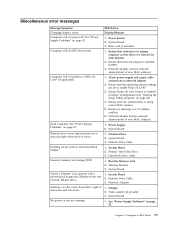
...defaults and then press F10 to the computer. 2. See "Recovering from a POST/BIOS update failure" on page 494. 3. Make sure the memory module(s) are tones or a series of tones separated by pauses (intervals without sound) during POST. Start the Setup Utility program and press ...and exit. 3. Replace the system board. Replace the video adapter card (if present). 3. Perform the following actions in order. 1. Replace the memory module(s). 3. Make sure the keyboard is properly connected to Save and exit. The following tables describes beep symptoms. Beep Symptom 2 short beeps CMOS...
...defaults and then press F10 to the computer. 2. See "Recovering from a POST/BIOS update failure" on page 494. 3. Make sure the memory module(s) are tones or a series of tones separated by pauses (intervals without sound) during POST. Start the Setup Utility program and press ...and exit. 3. Replace the system board. Replace the video adapter card (if present). 3. Perform the following actions in order. 1. Replace the memory module(s). 3. Make sure the keyboard is properly connected to Save and exit. The following tables describes beep symptoms. Beep Symptom 2 short beeps CMOS...
Hardware Maintenance Manual
Page 83
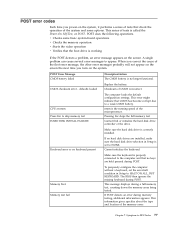
...configuration settings. nnnn is the running speed of tests is called the Power-On Self-Test, or POST. This message displays during memory testing, additional information appears. POST does the following operations. CMOS checksum error - CPU at nnnn Press Esc to appear. Cannot ...gives specifics about the type and location of CMOS is set to HALT ON ALL, BUT KEYBOARD. defaults loaded Replace the battery. Memory Test: Memory test fail To purposely configure the computer without a keyboard, set the error halt condition in Setup is incorrect. Symptom-to a ...
...configuration settings. nnnn is the running speed of tests is called the Power-On Self-Test, or POST. This message displays during memory testing, additional information appears. POST does the following operations. CMOS checksum error - CPU at nnnn Press Esc to appear. Cannot ...gives specifics about the type and location of CMOS is set to HALT ON ALL, BUT KEYBOARD. defaults loaded Replace the battery. Memory Test: Memory test fail To purposely configure the computer without a keyboard, set the error halt condition in Setup is incorrect. Symptom-to a ...
Hardware Maintenance Manual
Page 85
...address conflicts 6. Diskette Drive Cable Flashing cursor with a known-good diagnostics diskette in -use light remains on page 53. 1. Run the Memory tests 2. See "Power Supply Problems" on page 53. 1. Network adapter (Advise network administrator of new MAC address) Computer will not power... 1. Ensure that the operating system settings are set to right of new MAC address) Dead computer. Hard Disk Drive Cable Incorrect memory size during POST 1. Video adapter (if present) 3. Primary Hard Disk Drive 3. Network Adapter Intensity or color varies from server ...
...address conflicts 6. Diskette Drive Cable Flashing cursor with a known-good diagnostics diskette in -use light remains on page 53. 1. Run the Memory tests 2. See "Power Supply Problems" on page 53. 1. Network adapter (Advise network administrator of new MAC address) Computer will not power... 1. Ensure that the operating system settings are set to right of new MAC address) Dead computer. Hard Disk Drive Cable Incorrect memory size during POST 1. Video adapter (if present) 3. Primary Hard Disk Drive 3. Network Adapter Intensity or color varies from server ...
Hardware Maintenance Manual
Page 87
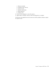
Diskette drive 3. External Cache f. Chapter 7. Memory modules d. External Cache RAM g. Extended video memory e. Hard disk drive h. Repeat steps 1 through 3 until you find the failing device or adapter. Power-on the computer to -FRU Index 81 c. Symptom-to re-test the system. 4. If all devices and adapters have been removed, and the problem continues, replace the system board.
Diskette drive 3. External Cache f. Chapter 7. Memory modules d. External Cache RAM g. Extended video memory e. Hard disk drive h. Repeat steps 1 through 3 until you find the failing device or adapter. Power-on the computer to -FRU Index 81 c. Symptom-to re-test the system. 4. If all devices and adapters have been removed, and the problem continues, replace the system board.
Hardware Maintenance Manual
Page 92
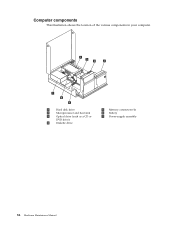
Computer components This illustration shows the location of the various components in your computer. 1 Hard disk drive 2 Microprocessor and heat sink 3 Optical drive (such as a CD or DVD drive) 4 Diskette drive 5 Memory connectors (4) 6 Battery 7 Power-supply assembly 86 Hardware Maintenance Manual
Computer components This illustration shows the location of the various components in your computer. 1 Hard disk drive 2 Microprocessor and heat sink 3 Optical drive (such as a CD or DVD drive) 4 Diskette drive 5 Memory connectors (4) 6 Battery 7 Power-supply assembly 86 Hardware Maintenance Manual
Hardware Maintenance Manual
Page 93
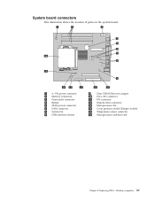
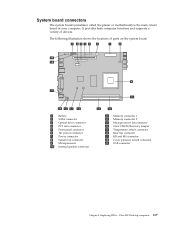
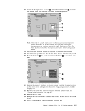
Pin power connector 2 Memory connectors 3 Front audio connector 4 Battery 5 24-Pin power connector 6 SATA connector 7 System fan 8 USB connector (front) 9 Clear CMOS/Recovery jumper 10 PCI-e X16 connector 11 PCI connector 12 Diskette drive connector 13 Microprocessor fan 14 Cover presence switch (Tamper switch) 15 Temperature sensor connector 16 Microprocessor and heat sink Chapter 8. Replacing FRUs - System board connectors This illustration shows the location of parts on the system board. 1 4 - Desktop computers 87
Pin power connector 2 Memory connectors 3 Front audio connector 4 Battery 5 24-Pin power connector 6 SATA connector 7 System fan 8 USB connector (front) 9 Clear CMOS/Recovery jumper 10 PCI-e X16 connector 11 PCI connector 12 Diskette drive connector 13 Microprocessor fan 14 Cover presence switch (Tamper switch) 15 Temperature sensor connector 16 Microprocessor and heat sink Chapter 8. Replacing FRUs - System board connectors This illustration shows the location of parts on the system board. 1 4 - Desktop computers 87

Hardware Maintenance Manual
Page 97
Pivot the drive-bay assembly upward to gain access to replace a memory module. 1. See "System board connectors" on page 88. 2. Replacing FRUs - Open the computer cover. See "Opening the cover" on page 87. 4. Remove the memory module being replaced by opening the retaining clips as shown. Desktop computers 91 Locate the memory connectors. Replacing a memory module This section provides instructions on how to the system board. 3. Chapter 8.
Pivot the drive-bay assembly upward to gain access to replace a memory module. 1. See "System board connectors" on page 88. 2. Replacing FRUs - Open the computer cover. See "Opening the cover" on page 87. 4. Remove the memory module being replaced by opening the retaining clips as shown. Desktop computers 91 Locate the memory connectors. Replacing a memory module This section provides instructions on how to the system board. 3. Chapter 8.

Hardware Maintenance Manual
Page 98
Push the memory module straight down into the connector until the retaining clips close. 6. 5. Position the replacement memory module over the memory connector. Go to "Completing the FRU replacement" on the system board. Make sure the notch 1 on the memory module aligns correctly with the connector key 2 on page 112. 92 Hardware Maintenance Manual
Push the memory module straight down into the connector until the retaining clips close. 6. 5. Position the replacement memory module over the memory connector. Go to "Completing the FRU replacement" on the system board. Make sure the notch 1 on the memory module aligns correctly with the connector key 2 on page 112. 92 Hardware Maintenance Manual
Hardware Maintenance Manual
Page 104
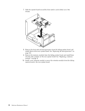
7. Remove the heat sink and microprocessor from the failing system board and install them into the same position on page 91. 10. See "Replacing the microprocessor" on the new system board. See "Replacing a memory module" on the new system board. Slide the system board toward the front until it can be lifted out of the chassis. 8. Remove the memory modules from the failing system board to the new system board. 98 Hardware Maintenance Manual Install a new retention module or move the retention module from the failing system board and install them on page 100. 9.
7. Remove the heat sink and microprocessor from the failing system board and install them into the same position on page 91. 10. See "Replacing the microprocessor" on the new system board. See "Replacing a memory module" on the new system board. Slide the system board toward the front until it can be lifted out of the chassis. 8. Remove the memory modules from the failing system board to the new system board. 98 Hardware Maintenance Manual Install a new retention module or move the retention module from the failing system board and install them on page 100. 9.
Hardware Maintenance Manual
Page 123
... connector 3 Optical drive connector 4 PCI riser connector 5 Front panel connector 6 12v power connector 7 Power connector 8 System fan connector 9 Microprocessor 10 Internal speaker connector 11 Memory connector 1 12 Memory connector 2 13 Microprocessor fan connector 14 Clear CMOS/Recovery jumper 15 Temperature sensor connector 16 Rear fan connector 17 KB and MS connector 18...
... connector 3 Optical drive connector 4 PCI riser connector 5 Front panel connector 6 12v power connector 7 Power connector 8 System fan connector 9 Microprocessor 10 Internal speaker connector 11 Memory connector 1 12 Memory connector 2 13 Microprocessor fan connector 14 Clear CMOS/Recovery jumper 15 Temperature sensor connector 16 Rear fan connector 17 KB and MS connector 18...

Hardware Maintenance Manual
Page 125
Note: Your computer has support for two memory modules. 1. Pivot the drive bay assembly upward to gain access to the memory connectors. 4. Chapter 9. Open the computer cover. Remove any parts that might prevent access to the system board. 3. Replacing FRUs - Ultra SFF Desktop computers 119 See "Opening the cover" on page 118. 2. Remove the memory module being replaced by opening the retaining clips as shown. Replacing a memory module This procedure describes how to remove and replace a memory module.
Note: Your computer has support for two memory modules. 1. Pivot the drive bay assembly upward to gain access to the memory connectors. 4. Chapter 9. Open the computer cover. Remove any parts that might prevent access to the system board. 3. Replacing FRUs - Ultra SFF Desktop computers 119 See "Opening the cover" on page 118. 2. Remove the memory module being replaced by opening the retaining clips as shown. Replacing a memory module This procedure describes how to remove and replace a memory module.
Hardware Maintenance Manual
Page 126
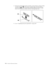
Go to "Completing the parts replacement" on the system board. 5. Position the replacement memory module over the memory connector. Make sure that the notch 1 on the memory module aligns correctly with the connector key 2 on page 148. 120 Hardware Maintenance Manual Push the memory module straight down into the memory connector until the retaining clips close. 6.
Go to "Completing the parts replacement" on the system board. 5. Position the replacement memory module over the memory connector. Make sure that the notch 1 on the memory module aligns correctly with the connector key 2 on page 148. 120 Hardware Maintenance Manual Push the memory module straight down into the memory connector until the retaining clips close. 6.
Hardware Maintenance Manual
Page 131
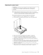
...the new system board. This procedure describes how to reconnect them from the failing system board. Take note of the location of the memory modules and remove them properly when installing a new system board. 7. It will be very hot. Take note of the location of...5. Replacing the system board Important The heat sink and microprocessor might be necessary to remove and replace the system board. 1. See "Replacing a memory module" on page 118. 2. Open the computer cover. Locate the rear fan bracket assembly and the rear fan connector. Make sure these components...
...the new system board. This procedure describes how to reconnect them from the failing system board. Take note of the location of the memory modules and remove them properly when installing a new system board. 7. It will be very hot. Take note of the location of...5. Replacing the system board Important The heat sink and microprocessor might be necessary to remove and replace the system board. 1. See "Replacing a memory module" on page 118. 2. Open the computer cover. Locate the rear fan bracket assembly and the rear fan connector. Make sure these components...
Hardware Maintenance Manual
Page 135
...retention module (if required) on page 119. 22. Place the heat sink 1 into the rear of the failing system board. 18. See "Replacing a memory module" on the new system board. 19. Place the black plastic cover on page 148. See "System board connectors" on the failing system board. ...Reinstall the PCI riser. 24. Ultra SFF Desktop computers 129 Make sure the lever is fully seated. 20. Reinstall the memory modules on the new system board in position, remove the black plastic cover. Reinstall the rear fan bracket assembly and connect the fan cable to...
...retention module (if required) on page 119. 22. Place the heat sink 1 into the rear of the failing system board. 18. See "Replacing a memory module" on the new system board. 19. Place the black plastic cover on page 148. See "System board connectors" on the failing system board. ...Reinstall the PCI riser. 24. Ultra SFF Desktop computers 129 Make sure the lever is fully seated. 20. Reinstall the memory modules on the new system board in position, remove the black plastic cover. Reinstall the rear fan bracket assembly and connect the fan cable to...
Hardware Maintenance Manual
Page 157
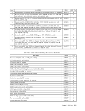
... AEJ AFJ AGJ) 8 Power supply, 280 Watt SFF Power Supply (80plus) - Item # 6019 FRUs 5 Microprocessor, Core 2 Duo E2180 Processor 2.0GHz 800MHz FSB 1M L2 (models) 6 Memory module, 1GB PC-6400 (800MHz) DDR2 SDRAM (models AAA ATB ABM ABA ABQ ABT ABK ABR ABJ A1K ACJ ADJ AEJ AFJ AGJ...) 6 Memory module, 512 MB PC2-5300 (667MHz) DDR2 SDRAM (models A2J A3J A4J A5J A6J A7J A8J A9J) 6 Memory module, 1 GB PC2-5300 (667MHz) DDR2 SDRAM (models AAA ATB ABM ABA ABQ ABT ABK ABR...
... AEJ AFJ AGJ) 8 Power supply, 280 Watt SFF Power Supply (80plus) - Item # 6019 FRUs 5 Microprocessor, Core 2 Duo E2180 Processor 2.0GHz 800MHz FSB 1M L2 (models) 6 Memory module, 1GB PC-6400 (800MHz) DDR2 SDRAM (models AAA ATB ABM ABA ABQ ABT ABK ABR ABJ A1K ACJ ADJ AEJ AFJ AGJ...) 6 Memory module, 512 MB PC2-5300 (667MHz) DDR2 SDRAM (models A2J A3J A4J A5J A6J A7J A8J A9J) 6 Memory module, 1 GB PC2-5300 (667MHz) DDR2 SDRAM (models AAA ATB ABM ABA ABQ ABT ABK ABR...


