Hardware Maintenance Manual
Page 49
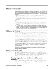
...system-controlled settings that works through the Windows operating system. Running diagnostics from http://www.lenovo.com/ support/. 2. To run PC-Doctor for Windows. To run diagnostics from the Windows desktop, select All Programs, select PC-Doctor for Windows, and click PC-Doctor for Windows..., open the Start menu from the Rescue and Recovery workspace, use the following procedure: © Lenovo 2005, 2008. Portions © IBM Corp...
...system-controlled settings that works through the Windows operating system. Running diagnostics from http://www.lenovo.com/ support/. 2. To run PC-Doctor for Windows. To run diagnostics from the Windows desktop, select All Programs, select PC-Doctor for Windows, and click PC-Doctor for Windows..., open the Start menu from the Rescue and Recovery workspace, use the following procedure: © Lenovo 2005, 2008. Portions © IBM Corp...

Hardware Maintenance Manual
Page 91
... SATA connector 11 USB connectors (4) 12 Ethernet connector 13 PCI Express x16 graphics adapter connector 14 PCI adapter connector 15 Serial connector (some models) Chapter 8. Desktop computers 85 Replacing FRUs -
... SATA connector 11 USB connectors (4) 12 Ethernet connector 13 PCI Express x16 graphics adapter connector 14 PCI adapter connector 15 Serial connector (some models) Chapter 8. Desktop computers 85 Replacing FRUs -
Hardware Maintenance Manual
Page 93
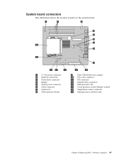
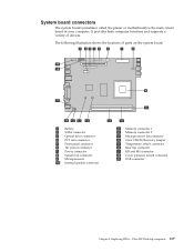
Replacing FRUs - Desktop computers 87 System board connectors This illustration shows the location of parts on the system board. 1 4 - Pin power connector 2 Memory connectors 3 Front audio connector 4 Battery 5 24-Pin power connector 6 SATA connector 7 System fan 8 USB connector (front) 9 Clear CMOS/Recovery jumper 10 PCI-e X16 connector 11 PCI connector 12 Diskette drive connector 13 Microprocessor fan 14 Cover presence switch (Tamper switch) 15 Temperature sensor connector 16 Microprocessor and heat sink Chapter 8.
Replacing FRUs - Desktop computers 87 System board connectors This illustration shows the location of parts on the system board. 1 4 - Pin power connector 2 Memory connectors 3 Front audio connector 4 Battery 5 24-Pin power connector 6 SATA connector 7 System fan 8 USB connector (front) 9 Clear CMOS/Recovery jumper 10 PCI-e X16 connector 11 PCI connector 12 Diskette drive connector 13 Microprocessor fan 14 Cover presence switch (Tamper switch) 15 Temperature sensor connector 16 Microprocessor and heat sink Chapter 8.
Hardware Maintenance Manual
Page 95
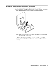
Note: Make sure you note the location of any cables that you close the cover to prevent damage to access the internal components. Open the computer cover. Accessing system board components and drives 1. On some models, you might need to pivot the drive-bay assembly upward and pivot the hard disk drive upward to the hard disk drive assembly. Replacing FRUs - See "Opening the cover" on page 88. 2. Desktop computers 89 Chapter 8. Attention: You must return the hard disk drive assembly to the latched position before you disconnect from the drives or the system board.
Note: Make sure you note the location of any cables that you close the cover to prevent damage to access the internal components. Open the computer cover. Accessing system board components and drives 1. On some models, you might need to pivot the drive-bay assembly upward and pivot the hard disk drive upward to the hard disk drive assembly. Replacing FRUs - See "Opening the cover" on page 88. 2. Desktop computers 89 Chapter 8. Attention: You must return the hard disk drive assembly to the latched position before you disconnect from the drives or the system board.

Hardware Maintenance Manual
Page 97
See "System board connectors" on page 88. 2. Chapter 8. Replacing FRUs - Remove the memory module being replaced by opening the retaining clips as shown. Desktop computers 91 Locate the memory connectors. Replacing a memory module This section provides instructions on how to the system board. 3. Open the computer cover. Pivot the drive-bay assembly upward to gain access to replace a memory module. 1. See "Opening the cover" on page 87. 4.
See "System board connectors" on page 88. 2. Chapter 8. Replacing FRUs - Remove the memory module being replaced by opening the retaining clips as shown. Desktop computers 91 Locate the memory connectors. Replacing a memory module This section provides instructions on how to the system board. 3. Open the computer cover. Pivot the drive-bay assembly upward to gain access to replace a memory module. 1. See "Opening the cover" on page 87. 4.

Hardware Maintenance Manual
Page 99
... cover, and connect the cables. Use the Setup Utility program to remove and replace the battery. See "Starting the Setup Utility program" on page 89. 4. Desktop computers 93 Locate the battery. Replacing FRUs - If the CMOS battery fails, the date, time, and configuration information (including passwords) are lost. Open the computer...
... cover, and connect the cables. Use the Setup Utility program to remove and replace the battery. See "Starting the Setup Utility program" on page 89. 4. Desktop computers 93 Locate the battery. Replacing FRUs - If the CMOS battery fails, the date, time, and configuration information (including passwords) are lost. Open the computer...
Hardware Maintenance Manual
Page 101
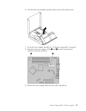
Disconnect the power supply cables 1 and 2 from the system-board connectors and from the cable clips and ties. Replacing FRUs - Desktop computers 95 6. Pivot the drive bay assembly upward to gain access to the system board. 7. Remove the power-supply cables from all drives. 9. Locate the power-supply assembly. See "Computer components" on page 86. 8. Chapter 8.
Disconnect the power supply cables 1 and 2 from the system-board connectors and from the cable clips and ties. Replacing FRUs - Desktop computers 95 6. Pivot the drive bay assembly upward to gain access to the system board. 7. Remove the power-supply cables from all drives. 9. Locate the power-supply assembly. See "Computer components" on page 86. 8. Chapter 8.

Hardware Maintenance Manual
Page 103
... card" on page 88. 2. See "System board connectors" on the blue strap at the front of the system board to release it from the chassis. Desktop computers 97 Pivot the drive-bay assembly upward to gain access to safely handle before continuing this procedure. Pull up on page 87. 6. Replacing the...
... card" on page 88. 2. See "System board connectors" on the blue strap at the front of the system board to release it from the chassis. Desktop computers 97 Pivot the drive-bay assembly upward to gain access to safely handle before continuing this procedure. Pull up on page 87. 6. Replacing the...

Hardware Maintenance Manual
Page 105
Reconnect all cables that it to "Completing the FRU replacement" on page 112. Chapter 8. Desktop computers 99 11. Go to the rear of the chassis until it is aligned with the mounting studs then slide it is fully seated. 12. Replacing FRUs - Position the new system board so that were disconnected from the system board. See "Replacing an adapter card" on page 117. 14. Reinstall any PCI adapters that were removed. See "System board connectors" on page 90. 13.
Reconnect all cables that it to "Completing the FRU replacement" on page 112. Chapter 8. Desktop computers 99 11. Go to the rear of the chassis until it is aligned with the mounting studs then slide it is fully seated. 12. Replacing FRUs - Position the new system board so that were disconnected from the system board. See "Replacing an adapter card" on page 117. 14. Reinstall any PCI adapters that were removed. See "System board connectors" on page 90. 13.

Hardware Maintenance Manual
Page 107
If you must touch the microprocessor, touch only the sides. Important Do not touch the gold contacts on the bottom of the socket. 4. Chapter 8. Replacing FRUs - Remove the microprocessor from the failing system board, release the lever 1 securing the microprocessor 2 then pivot the microprocessor retainer 3 until it out of the microprocessor. Desktop computers 101 To remove the microprocessor from the system board socket by lifting it is fully open. 5.
If you must touch the microprocessor, touch only the sides. Important Do not touch the gold contacts on the bottom of the socket. 4. Chapter 8. Replacing FRUs - Remove the microprocessor from the failing system board, release the lever 1 securing the microprocessor 2 then pivot the microprocessor retainer 3 until it out of the microprocessor. Desktop computers 101 To remove the microprocessor from the system board socket by lifting it is fully open. 5.

Hardware Maintenance Manual
Page 109
Lower the microprocessor retainer 3 and then lower the lever 1 to secure the heat sink. 11. Desktop computers 103 Place the heat sink into position. 10. Chapter 8. 9. Make sure the lever is securely locked into position and lower the lever to secure the retainer. Go to "Completing the FRU replacement" on page 112. Replacing FRUs -
Lower the microprocessor retainer 3 and then lower the lever 1 to secure the heat sink. 11. Desktop computers 103 Place the heat sink into position. 10. Chapter 8. 9. Make sure the lever is securely locked into position and lower the lever to secure the retainer. Go to "Completing the FRU replacement" on page 112. Replacing FRUs -

Hardware Maintenance Manual
Page 111
... the recesses in the hard disk drive bracket. Remove the failing hard disk drive from the rear of the hard disk drive. 7. Replacing FRUs - Chapter 8. Desktop computers 105 4. Disconnect the signal and power cables from the bracket by flexing the bracket as shown. 6.
... the recesses in the hard disk drive bracket. Remove the failing hard disk drive from the rear of the hard disk drive. 7. Replacing FRUs - Chapter 8. Desktop computers 105 4. Disconnect the signal and power cables from the bracket by flexing the bracket as shown. 6.

Hardware Maintenance Manual
Page 113
Replacing FRUs - Install the new optical drive into the bay and slide it on page 112. Connect the signal and power cables to "Completing the FRU replacement" on the new drive. 6. Chapter 8. 5. Desktop computers 107 Remove the lock bracket from the drive being replaced and install it to the locked position. 7. Go to the rear of the optical drive. 8.
Replacing FRUs - Install the new optical drive into the bay and slide it on page 112. Connect the signal and power cables to "Completing the FRU replacement" on the new drive. 6. Chapter 8. 5. Desktop computers 107 Remove the lock bracket from the drive being replaced and install it to the locked position. 7. Go to the rear of the optical drive. 8.

Hardware Maintenance Manual
Page 115
Replacing FRUs - 5. Chapter 8. Install the new diskette drive into the bay and slide it on page 112. Remove the lock bracket from the rear of the failing diskette drive. 6. Go to the locked position. 9. Disconnect the flat cable from the drive being replaced and install it to "Completing the FRU replacement" on the new drive. 8. Connect the flat cable to the new diskette drive. 7. Desktop computers 109
Replacing FRUs - 5. Chapter 8. Install the new diskette drive into the bay and slide it on page 112. Remove the lock bracket from the rear of the failing diskette drive. 6. Go to the locked position. 9. Disconnect the flat cable from the drive being replaced and install it to "Completing the FRU replacement" on the new drive. 8. Connect the flat cable to the new diskette drive. 7. Desktop computers 109

Hardware Maintenance Manual
Page 117
... "System board connectors" on page 112. Replacing FRUs - 4. New rubber mounts might come with four rubber mounts that protrude through the holes with your fingers. 9. Desktop computers 111 Go to the system board. Reinstall the fan mounting bracket into the mounting bracket. 8. The fan assembly is mounted with the new fan...
... "System board connectors" on page 112. Replacing FRUs - 4. New rubber mounts might come with four rubber mounts that protrude through the holes with your fingers. 9. Desktop computers 111 Go to the system board. Reinstall the fan mounting bracket into the mounting bracket. 8. The fan assembly is mounted with the new fan...
Hardware Maintenance Manual
Page 119
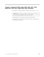
... all FRUs. Only the major FRUs are to be done by trained service technicians only. This chapter does not contain a remove and replace procedure for desktop computers of the following machine types: xxxx, xxxx. Important Before you work safely. These precautions and guidelines will help you replace any FRU, read Chapter...
... all FRUs. Only the major FRUs are to be done by trained service technicians only. This chapter does not contain a remove and replace procedure for desktop computers of the following machine types: xxxx, xxxx. Important Before you work safely. These precautions and guidelines will help you replace any FRU, read Chapter...

Hardware Maintenance Manual
Page 121
Replacing FRUs - Ultra SFF Desktop computers 115 Rear connectors The following illustration shows the location of connectors on the rear of the computer. 1 PCI adapter connector 2 Integrated cable lock-latch 3 USB connector 4 USB connector 5 VGA monitor connector 6 Parallel connector 7 Serial connector 8 Ethernet connector 9 USB connectors (2) 10 ESATA connector 11 USB connectors (2) 12 Audio-line-out connector 13 Audio-line-in connector 14 Power supply diagnostic LEDs (some models) 15 Power connector Chapter 9.
Replacing FRUs - Ultra SFF Desktop computers 115 Rear connectors The following illustration shows the location of connectors on the rear of the computer. 1 PCI adapter connector 2 Integrated cable lock-latch 3 USB connector 4 USB connector 5 VGA monitor connector 6 Parallel connector 7 Serial connector 8 Ethernet connector 9 USB connectors (2) 10 ESATA connector 11 USB connectors (2) 12 Audio-line-out connector 13 Audio-line-in connector 14 Power supply diagnostic LEDs (some models) 15 Power connector Chapter 9.
Hardware Maintenance Manual
Page 123
... KB and MS connector 18 Cover presence switch connector 19 USB connector Chapter 9. The following illustration shows the locations of devices. Replacing FRUs - Ultra SFF Desktop computers 117 System board connectors The system board (sometimes called the planar or motherboard) is the main circuit board in your computer.
... KB and MS connector 18 Cover presence switch connector 19 USB connector Chapter 9. The following illustration shows the locations of devices. Replacing FRUs - Ultra SFF Desktop computers 117 System board connectors The system board (sometimes called the planar or motherboard) is the main circuit board in your computer.

Hardware Maintenance Manual
Page 125
Pivot the drive bay assembly upward to gain access to the memory connectors. 4. Remove any parts that might prevent access to the system board. 3. Chapter 9. Open the computer cover. See "Opening the cover" on page 118. 2. Replacing FRUs - Remove the memory module being replaced by opening the retaining clips as shown. Ultra SFF Desktop computers 119 Replacing a memory module This procedure describes how to remove and replace a memory module. Note: Your computer has support for two memory modules. 1.
Pivot the drive bay assembly upward to gain access to the memory connectors. 4. Remove any parts that might prevent access to the system board. 3. Chapter 9. Open the computer cover. See "Opening the cover" on page 118. 2. Replacing FRUs - Remove the memory module being replaced by opening the retaining clips as shown. Ultra SFF Desktop computers 119 Replacing a memory module This procedure describes how to remove and replace a memory module. Note: Your computer has support for two memory modules. 1.

Hardware Maintenance Manual
Page 127
Important Refer to "Completing the parts replacement" on page 118. 2. Open the computer cover. You might be displayed. Ultra SFF Desktop computers 121 See the system board illustration for information about replacing and disposing of the battery. Remove the old battery. 5. Go to "Safety notices (multi-...
Important Refer to "Completing the parts replacement" on page 118. 2. Open the computer cover. You might be displayed. Ultra SFF Desktop computers 121 See the system board illustration for information about replacing and disposing of the battery. Remove the old battery. 5. Go to "Safety notices (multi-...


