Hardware Maintenance Manual
Page 5
...Lenovo 2005, 2008. Replacing FRUs (Types 6062, 6065, 6071, 6076, 6089, 9011, 9014, 9071, 9089, 9162, 9182, and 9303 113 Locations 114 Front connectors 114 Rear connectors 115 Computer components 116 System board connectors 117 Opening the cover 118 Replacing a memory module 119 Replacing the CMOS battery 121 Replacing the power supply... fan assembly 110 Completing the FRU replacement 112 Chapter 9. FRU lists 149 Machine Type 6019 149 iii Power Supply Problems 53 Diagnostic error codes 54 Beep symptoms 76 POST error codes 77 Miscellaneous error messages 79 Undetermined ...
...Lenovo 2005, 2008. Replacing FRUs (Types 6062, 6065, 6071, 6076, 6089, 9011, 9014, 9071, 9089, 9162, 9182, and 9303 113 Locations 114 Front connectors 114 Rear connectors 115 Computer components 116 System board connectors 117 Opening the cover 118 Replacing a memory module 119 Replacing the CMOS battery 121 Replacing the power supply... fan assembly 110 Completing the FRU replacement 112 Chapter 9. FRU lists 149 Machine Type 6019 149 iii Power Supply Problems 53 Diagnostic error codes 54 Beep symptoms 76 POST error codes 77 Miscellaneous error messages 79 Undetermined ...
Hardware Maintenance Manual
Page 10
... familiar with live electrical currents. Ensure that has hazardous voltages. Use only one hand when working with a soft material that supplies power to the machine and to switch off . 4 Hardware Maintenance Manual Stand on suitable rubber mats (obtained locally, if necessary)... procedures. To avoid personal injury or equipment damage, disconnect the attached power cords, telecommunication systems, networks, and modems before : - v Do not work alone under hazardous conditions or near power supplies - Observe the special safety precautions when you open the server/workstation ...
... familiar with live electrical currents. Ensure that has hazardous voltages. Use only one hand when working with a soft material that supplies power to the machine and to switch off . 4 Hardware Maintenance Manual Stand on suitable rubber mats (obtained locally, if necessary)... procedures. To avoid personal injury or equipment damage, disconnect the attached power cords, telecommunication systems, networks, and modems before : - v Do not work alone under hazardous conditions or near power supplies - Observe the special safety precautions when you open the server/workstation ...
Hardware Maintenance Manual
Page 11
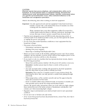
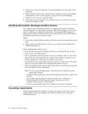
...Examples of features or options not covered by this inspection guide is conductive; such touching can continue without first correcting the problem. Power supply units - Blowers and fans - Send another person to measure third-wire ground continuity for 0.1 ohm or less between the external ...The intent of steps presented in the parts listings. Consider these conditions and the safety hazards they are moist floors, nongrounded power extension cables, power surges, and missing safety grounds. b. Insulation must determine how serious the apparent hazard could be and whether you must ...
...Examples of features or options not covered by this inspection guide is conductive; such touching can continue without first correcting the problem. Power supply units - Blowers and fans - Send another person to measure third-wire ground continuity for 0.1 ohm or less between the external ...The intent of steps presented in the parts listings. Consider these conditions and the safety hazards they are moist floors, nongrounded power extension cables, power surges, and missing safety grounds. b. Insulation must determine how serious the apparent hazard could be and whether you must ...
Hardware Maintenance Manual
Page 12
... for operator safety and correct system function. Check that the ESD protective devices you are all at the same charge. Notes: 1. Make sure that the power-supply cover fasteners (screws or rivets) have been certified (ISO 9000) as to the safety of a grounding system is desirable but not required to electrostatic discharge...
... for operator safety and correct system function. Check that the ESD protective devices you are all at the same charge. Notes: 1. Make sure that the power-supply cover fasteners (screws or rivets) have been certified (ISO 9000) as to the safety of a grounding system is desirable but not required to electrostatic discharge...
Hardware Maintenance Manual
Page 15
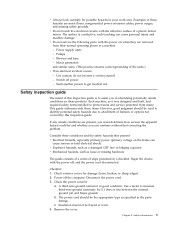
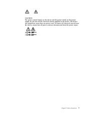
Safety information 9 To remove all electrical current from the device, ensure that all power cords are disconnected from the power source. 2 1 Chapter 2. The device also might have more than one power cord. CAUTION: The power control button on the device and the power switch on the power supply do not turn off the electrical current supplied to the device.
Safety information 9 To remove all electrical current from the device, ensure that all power cords are disconnected from the power source. 2 1 Chapter 2. The device also might have more than one power cord. CAUTION: The power control button on the device and the power switch on the power supply do not turn off the electrical current supplied to the device.
Hardware Maintenance Manual
Page 59
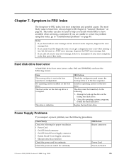
...No operating system installed on Switch © Lenovo 2005, 2008. The drive is listed first. Power Supply Problems If you did receive a POST error message, diagnose the POST error message first. FRU/Action Reseat connectors Power Cord Power-on the boot drive. Symptom-to-FRU Index...system on page 41. Attempt to have available when servicing a computer. v Power Cord v On/Off Switch connector v On/Off Switch Power Supply connector v System Board Power Supply connectors v Microprocessor(s) connection Check the power cord for a description of your error symptoms in the first part of this...
...No operating system installed on Switch © Lenovo 2005, 2008. The drive is listed first. Power Supply Problems If you did receive a POST error message, diagnose the POST error message first. FRU/Action Reseat connectors Power Cord Power-on the boot drive. Symptom-to-FRU Index...system on page 41. Attempt to have available when servicing a computer. v Power Cord v On/Off Switch connector v On/Off Switch Power Supply connector v System Board Power Supply connectors v Microprocessor(s) connection Check the power cord for a description of your error symptoms in the first part of this...
Hardware Maintenance Manual
Page 72
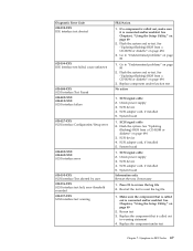
... 5. Re-run test 3. Riser card, if installed 3. Re-start the test, if necessary 1. Reseat IDE signal cable 4. Flash the system. Check power supply 3. Replace the component that is connected and/or enabled. System board Information only Re-start the test to "Undetermined problems" on page 49 2. See ...1. Go to reset the log file 1. See Chapter 6, "Using the Setup Utility," on page 80 2. Reseat IDE signal cable 4. Check power supply voltages 3. IDE signal cable 2. Press F3 to review the log file 2. Flash the system and re-test. Make sure the component that is...
... 5. Re-run test 3. Riser card, if installed 3. Re-start the test, if necessary 1. Reseat IDE signal cable 4. Flash the system. Check power supply 3. Replace the component that is connected and/or enabled. System board Information only Re-start the test to "Undetermined problems" on page 49 2. See ...1. Go to reset the log file 1. See Chapter 6, "Using the Setup Utility," on page 80 2. Reseat IDE signal cable 4. Check power supply voltages 3. IDE signal cable 2. Press F3 to review the log file 2. Flash the system and re-test. Make sure the component that is...
Hardware Maintenance Manual
Page 73
...," on page 49 2. See "Updating (flashing) BIOS from a CD-ROM or diskette" on page 80 2. SCSI device 4. Check power supply 3. If a component is called out is connected and/or enabled. SCSI device 4. Check power supply 3. See "Updating (flashing) BIOS from a CD-ROM or diskette" on page 80 1. SCSI signal cable 2. Re-start the test...
...," on page 49 2. See "Updating (flashing) BIOS from a CD-ROM or diskette" on page 80 2. SCSI device 4. Check power supply 3. If a component is called out is connected and/or enabled. SCSI device 4. Check power supply 3. See "Updating (flashing) BIOS from a CD-ROM or diskette" on page 80 1. SCSI signal cable 2. Re-start the test...
Hardware Maintenance Manual
Page 78
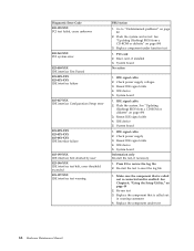
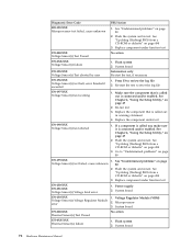
...-0XX-XXX Thermal Sensor(s) failure 1. See "Undetermined problems" on page 49 2. Press F3 to "Undetermined problems" on page 494 3. See "Undetermined problems" on page 494 3. Power supply 2. Voltage Regulator Module (VRM) 2. Replace component under test 170-198-XXX Voltage Sensor(s) test aborted 1. Re-start the test, if necessary 170-196-XXX Voltage...
...-0XX-XXX Thermal Sensor(s) failure 1. See "Undetermined problems" on page 49 2. Press F3 to "Undetermined problems" on page 494 3. See "Undetermined problems" on page 494 3. Power supply 2. Voltage Regulator Module (VRM) 2. Replace component under test 170-198-XXX Voltage Sensor(s) test aborted 1. Re-start the test, if necessary 170-196-XXX Voltage...
Hardware Maintenance Manual
Page 79
... from a CD-ROM or diskette" on page 49 2. System board 1. Microprocessor Chapter 7. Flash system 2. Assure Asset Security Enabled 2. System board 3. Replace component under test 1. Check Power supply voltages 3. System board No action 1. Symptom-to review the log file 2. See Chapter 6, "Using the Setup Utility," on page 494 3. Replace the memory module called...
... from a CD-ROM or diskette" on page 49 2. System board 1. Microprocessor Chapter 7. Flash system 2. Assure Asset Security Enabled 2. System board 3. Replace component under test 1. Check Power supply voltages 3. System board No action 1. Symptom-to review the log file 2. See Chapter 6, "Using the Setup Utility," on page 494 3. Replace the memory module called...
Hardware Maintenance Manual
Page 80
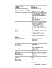
...drive 4. Reseat the hard disk drive cable 4. Hard Disk Drive Cable 2. SCSI adapter card 6. Check and test mouse 3. System board 1. Check power supply voltages 3. Hard Disk drive (SCSI) 5. System board No action No action 1. Diskette drive 4. Reseat the hard disk drive cable 4. Remove the... Hi-Capacity Cartridge Drive and re-test the system 1. Mouse 2. Check power supply voltages 3. Hard Disk drive (IDE) 5. System board No action 1. System board No action Remove the Joystick and re-test the system ...
...drive 4. Reseat the hard disk drive cable 4. Hard Disk Drive Cable 2. SCSI adapter card 6. Check and test mouse 3. System board 1. Check power supply voltages 3. Hard Disk drive (SCSI) 5. System board No action No action 1. Diskette drive 4. Reseat the hard disk drive cable 4. Remove the... Hi-Capacity Cartridge Drive and re-test the system 1. Mouse 2. Check power supply voltages 3. Hard Disk drive (IDE) 5. System board No action 1. System board No action Remove the Joystick and re-test the system ...
Hardware Maintenance Manual
Page 85
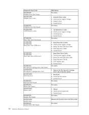
...first device after diskette 2. System Board ″Insert a Diskette″ icon appears with an otherwise blank display. 1. See "Power Supply Problems" on page 53. 1. Riser card, if installed Computer will not RPL from left to enable Wake on page 53. 1. Check... power supply and signal cable connections to -FRU Index 79 See "Power Supply Problems" on page 53. System Board 2. Memory Module 3. System Board No power or fan not running 1. System Board 2. Ensure that network adapter is enabled...
...first device after diskette 2. System Board ″Insert a Diskette″ icon appears with an otherwise blank display. 1. See "Power Supply Problems" on page 53. 1. Riser card, if installed Computer will not RPL from left to enable Wake on page 53. 1. Check... power supply and signal cable connections to -FRU Index 79 See "Power Supply Problems" on page 53. System Board 2. Memory Module 3. System Board No power or fan not running 1. System Board 2. Ensure that network adapter is enabled...
Hardware Maintenance Manual
Page 86
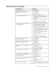
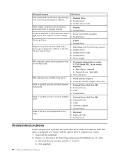
... the keyboard do not work 1. System Board Printer problems 1. System Board Program loads from its own hard disk. 1. Diskette Drive 3. Power Supply RPL computer cannot access programs from the hard disk with a known-good diagnostic diskette. 1. Check startup sequence 2. External Device Self-Test OK...1. Remove or disconnect the following components (if installed) one at a time. System Board 3. Cable 4. Keyboard Cable 3. Power-off the computer. 2. Diskette Drive Cable Other display symptoms not listed above (including blank or illegible display) 1. System Board...
... the keyboard do not work 1. System Board Printer problems 1. System Board Program loads from its own hard disk. 1. Diskette Drive 3. Power Supply RPL computer cannot access programs from the hard disk with a known-good diagnostic diskette. 1. Check startup sequence 2. External Device Self-Test OK...1. Remove or disconnect the following components (if installed) one at a time. System Board 3. Cable 4. Keyboard Cable 3. Power-off the computer. 2. Diskette Drive Cable Other display symptoms not listed above (including blank or illegible display) 1. System Board...

Hardware Maintenance Manual
Page 91
... determine where to connect the cables on the rear of connectors on your computer. Rear connectors This illustration shows the location of your computer. 1 Power cord connector 2 Power-supply-diagnostic LEDs (some models) 3 Audio-line-in connector 4 Audio-line-out connector 5 Microphone 6 Serial connector 7 Parallel connector 8 VGA-monitor connector 9 USB connectors (2) 10 External...
... determine where to connect the cables on the rear of connectors on your computer. Rear connectors This illustration shows the location of your computer. 1 Power cord connector 2 Power-supply-diagnostic LEDs (some models) 3 Audio-line-in connector 4 Audio-line-out connector 5 Microphone 6 Serial connector 7 Parallel connector 8 VGA-monitor connector 9 USB connectors (2) 10 External...
Hardware Maintenance Manual
Page 92
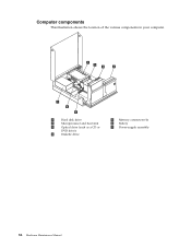
Computer components This illustration shows the location of the various components in your computer. 1 Hard disk drive 2 Microprocessor and heat sink 3 Optical drive (such as a CD or DVD drive) 4 Diskette drive 5 Memory connectors (4) 6 Battery 7 Power-supply assembly 86 Hardware Maintenance Manual
Computer components This illustration shows the location of the various components in your computer. 1 Hard disk drive 2 Microprocessor and heat sink 3 Optical drive (such as a CD or DVD drive) 4 Diskette drive 5 Memory connectors (4) 6 Battery 7 Power-supply assembly 86 Hardware Maintenance Manual
Hardware Maintenance Manual
Page 100
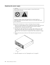
...cables, and any other cables that secure the power supply. 5. Open the computer cover. This procedure describes how to the computer. Remove any media (diskettes, CDs, or tapes) from the drives, shut down your operating system, and turn off all power cords from electrical outlets. 3. Disconnect the cables... attached to remove and replace the power supply. 1. Remove the four screws at the rear of the chassis that are connected to the computer....
...cables, and any other cables that secure the power supply. 5. Open the computer cover. This procedure describes how to the computer. Remove any media (diskettes, CDs, or tapes) from the drives, shut down your operating system, and turn off all power cords from electrical outlets. 3. Disconnect the cables... attached to remove and replace the power supply. 1. Remove the four screws at the rear of the chassis that are connected to the computer....
Hardware Maintenance Manual
Page 101
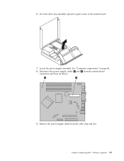
See "Computer components" on page 86. 8. 6. Disconnect the power supply cables 1 and 2 from the system-board connectors and from the cable clips and ties. Replacing FRUs - Chapter 8. Pivot the drive bay assembly upward to gain access to the system board. 7. Locate the power-supply assembly. Desktop computers 95 Remove the power-supply cables from all drives. 9.
See "Computer components" on page 86. 8. 6. Disconnect the power supply cables 1 and 2 from the system-board connectors and from the cable clips and ties. Replacing FRUs - Chapter 8. Pivot the drive bay assembly upward to gain access to the system board. 7. Locate the power-supply assembly. Desktop computers 95 Remove the power-supply cables from all drives. 9.
Hardware Maintenance Manual
Page 102
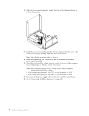
...selection switch on page 112. 96 Hardware Maintenance Manual These computers automatically control the voltage. Install the new power-supply assembly into the chassis so that the screw holes in the power-supply assembly align with those in the chassis. Install and tighten the four screws at the rear of the ... the rear of the chassis and remove it from the computer. 11. Note: Use only the screws provided by Lenovo. 12. Reconnect all the power supply cables to 230 V. 14. v If the voltage supply range is 100-127 V ac, set the switch to the drives and the system board. 15. 10. Slide...
...selection switch on page 112. 96 Hardware Maintenance Manual These computers automatically control the voltage. Install the new power-supply assembly into the chassis so that the screw holes in the power-supply assembly align with those in the chassis. Install and tighten the four screws at the rear of the ... the rear of the chassis and remove it from the computer. 11. Note: Use only the screws provided by Lenovo. 12. Reconnect all the power supply cables to 230 V. 14. v If the voltage supply range is 100-127 V ac, set the switch to the drives and the system board. 15. 10. Slide...
Hardware Maintenance Manual
Page 118
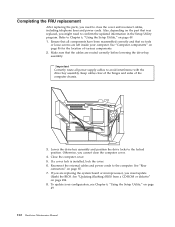
... loose screws are left inside your configuration, see Chapter 6, "Using the Setup Utility," on page 85. 7. Reconnect the external cables and power cords to Chapter 6, "Using the Setup Utility," on the part that was replaced, you cannot close the cover and reconnect cables, including...the drive-bay assembly. Completing the FRU replacement After replacing the parts, you must update (flash) the BIOS. Ensure that all power supply cables to the locked position. Important Correctly route all components have been reassembled correctly and that the cables are replacing the system ...
... loose screws are left inside your configuration, see Chapter 6, "Using the Setup Utility," on page 85. 7. Reconnect the external cables and power cords to Chapter 6, "Using the Setup Utility," on the part that was replaced, you cannot close the cover and reconnect cables, including...the drive-bay assembly. Completing the FRU replacement After replacing the parts, you must update (flash) the BIOS. Ensure that all power supply cables to the locked position. Important Correctly route all components have been reassembled correctly and that the cables are replacing the system ...

Hardware Maintenance Manual
Page 121
Rear connectors The following illustration shows the location of connectors on the rear of the computer. 1 PCI adapter connector 2 Integrated cable lock-latch 3 USB connector 4 USB connector 5 VGA monitor connector 6 Parallel connector 7 Serial connector 8 Ethernet connector 9 USB connectors (2) 10 ESATA connector 11 USB connectors (2) 12 Audio-line-out connector 13 Audio-line-in connector 14 Power supply diagnostic LEDs (some models) 15 Power connector Chapter 9. Ultra SFF Desktop computers 115 Replacing FRUs -
Rear connectors The following illustration shows the location of connectors on the rear of the computer. 1 PCI adapter connector 2 Integrated cable lock-latch 3 USB connector 4 USB connector 5 VGA monitor connector 6 Parallel connector 7 Serial connector 8 Ethernet connector 9 USB connectors (2) 10 ESATA connector 11 USB connectors (2) 12 Audio-line-out connector 13 Audio-line-in connector 14 Power supply diagnostic LEDs (some models) 15 Power connector Chapter 9. Ultra SFF Desktop computers 115 Replacing FRUs -


