

Hardware Maintenance Manual
Page 5
... 7819, 9686, 9687, 9688, 9689, 9690, and 9691) . . . . . 121 Rear connectors 122 Removing the cover 123 Locations 124 Locating parts on the system board 87 Machine types 7812, 7813, 9680 and 9681 . . . 87 Machine types 7814, 7815, 9682 and 9683 . . . ... PC-Doctor for DOS 46 Creating a diagnostic CD image 46 Creating diagnostic diskettes 46 Running diagnostics from the Setup Utility program . . . . . 54 © Lenovo 2005, 2008. Chapter 7. About this manual . . . . . 1 Important Safety Information 1 Important information about replacing RoHS compliant FRUs 2 Chapter 2. General Checkout...
... 7819, 9686, 9687, 9688, 9689, 9690, and 9691) . . . . . 121 Rear connectors 122 Removing the cover 123 Locations 124 Locating parts on the system board 87 Machine types 7812, 7813, 9680 and 9681 . . . 87 Machine types 7814, 7815, 9682 and 9683 . . . ... PC-Doctor for DOS 46 Creating a diagnostic CD image 46 Creating diagnostic diskettes 46 Running diagnostics from the Setup Utility program . . . . . 54 © Lenovo 2005, 2008. Chapter 7. About this manual . . . . . 1 Important Safety Information 1 Important information about replacing RoHS compliant FRUs 2 Chapter 2. General Checkout...

Hardware Maintenance Manual
Page 7
...245;es Es importante que lea todas las declaraciones de precaución y de peligro de este manual antes de seguir las instrucciones. © Lenovo 2005, 2008. It is intended only for each machine type and model listed on the cover. This manual includes a complete FRU... part number listing for trained servicers who are familiar with Lenovo computer products. If you have internet access, FRU part numbers are applicable to any of the instructions. Veuillez lire toutes les consignes de type DANGER...
...245;es Es importante que lea todas las declaraciones de precaución y de peligro de este manual antes de seguir las instrucciones. © Lenovo 2005, 2008. It is intended only for each machine type and model listed on the cover. This manual includes a complete FRU... part number listing for trained servicers who are familiar with Lenovo computer products. If you have internet access, FRU part numbers are applicable to any of the instructions. Veuillez lire toutes les consignes de type DANGER...
Hardware Maintenance Manual
Page 8
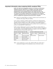
...Products on the market and sold in Electrical and Electronic Equipment Directive (2002/95/EC) is a part with unique FRU part numbers. The following statement pertains to support Lenovo's requirements and schedule in the European Union after June 2006 Current or original Replacement FRU... Restriction of order. 2 Hardware Maintenance Manual RoHS requirements must also be implemented on Lenovo products placed on the market before June 2006 are identified with a different FRU part number that is automatically shipped by the distribution center at the time of Hazardous Substances...
...Products on the market and sold in Electrical and Electronic Equipment Directive (2002/95/EC) is a part with unique FRU part numbers. The following statement pertains to support Lenovo's requirements and schedule in the European Union after June 2006 Current or original Replacement FRU... Restriction of order. 2 Hardware Maintenance Manual RoHS requirements must also be implemented on Lenovo products placed on the market before June 2006 are identified with a different FRU part number that is automatically shipped by the distribution center at the time of Hazardous Substances...
Hardware Maintenance Manual
Page 9
... : hammering, drilling soldering, cutting wire, attaching springs, using solvents, or working in any other parts in a safe place, away from the muscles in the moving parts of the object equally between your leg muscles; Electrical safety © Lenovo 2005, 2008. v Do not wear loose clothing that might be hazardous to your elbows. v Do...
... : hammering, drilling soldering, cutting wire, attaching springs, using solvents, or working in any other parts in a safe place, away from the muscles in the moving parts of the object equally between your leg muscles; Electrical safety © Lenovo 2005, 2008. v Do not wear loose clothing that might be hazardous to your elbows. v Do...

Hardware Maintenance Manual
Page 11
The surface is to attachment of the following parts with the power on when they are removed from injury. Power supply units - Use caution; Switch off power. - If you relocate your computer to another ...
The surface is to attachment of the following parts with the power on when they are removed from injury. Power supply units - Use caution; Switch off power. - If you relocate your computer to another ...
Hardware Maintenance Manual
Page 12
... third-wire ground connector in a checklist. b. Remove the cover. 5. Check for any obvious alterations. When handling ESD-sensitive parts: v Keep the parts in protective packages until they are all at the same charge. Disconnect the power cord. 3. Check that the ESD protective devices... you can occur when there is a difference in the parts listings. ESD damage can continue without first correcting the problem. Checklist: 1. Insulation must determine how serious the apparent hazard could...
... third-wire ground connector in a checklist. b. Remove the cover. 5. Check for any obvious alterations. When handling ESD-sensitive parts: v Keep the parts in protective packages until they are all at the same charge. Disconnect the power cord. 3. Check that the ESD protective devices... you can occur when there is a difference in the parts listings. ESD damage can continue without first correcting the problem. Checklist: 1. Insulation must determine how serious the apparent hazard could...
Hardware Maintenance Manual
Page 13
... of a grounding system is hazardous. To avoid a shock hazard: v Do not connect or disconnect any frame ground, ground braid, or green-wire ground. - v Prevent the part from power, telephone and communication cables is desirable but not required to a properly wired and grounded electrical outlet. Use an ESD common ground or reference...
... of a grounding system is hazardous. To avoid a shock hazard: v Do not connect or disconnect any frame ground, ground braid, or green-wire ground. - v Prevent the part from power, telephone and communication cables is desirable but not required to a properly wired and grounded electrical outlet. Use an ESD common ground or reference...
Hardware Maintenance Manual
Page 15
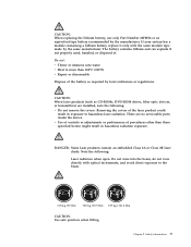
...;C (212°F) v Repair or disassemble Dispose of . There are installed, note the following : Laser radiation when open. CAUTION: When replacing the lithium battery, use only Part Number 33F8354 or an equivalent type battery recommended by the same manufacturer. The battery contains lithium and can explode if not properly used, handled, or...
...;C (212°F) v Repair or disassemble Dispose of . There are installed, note the following : Laser radiation when open. CAUTION: When replacing the lithium battery, use only Part Number 33F8354 or an equivalent type battery recommended by the same manufacturer. The battery contains lithium and can explode if not properly used, handled, or...

Hardware Maintenance Manual
Page 45
...can find the following information: v CRU removal and installation instructions v Publications v Troubleshooting information v Parts information v Downloads and drivers v Links to http://www.lenovo.com/ support/. © Lenovo 2005, 2008. Easy network connectivity and management v Message Center with support in one convenient place for... your major tasks, your computer is available from the Windows® desktop, select All Programs, select Lenovo Care, and click Lenovo Care. Managing multimedia software - Portions © IBM Corp. 2005. 39 Additional information resources If you...
...can find the following information: v CRU removal and installation instructions v Publications v Troubleshooting information v Parts information v Downloads and drivers v Links to http://www.lenovo.com/ support/. © Lenovo 2005, 2008. Easy network connectivity and management v Message Center with support in one convenient place for... your major tasks, your computer is available from the Windows® desktop, select All Programs, select Lenovo Care, and click Lenovo Care. Managing multimedia software - Portions © IBM Corp. 2005. 39 Additional information resources If you...

Hardware Maintenance Manual
Page 49
... diagnostic program calls out or go to step 6. Power-off the computer and all cables and power cords. 3. If you receive an error, replace the part that the latest level of the problem: 1. v If you did not receive the correct response, proceed to "POST error codes" on the system. If possible...-on page 56. A down-level BIOS might have this information available when requesting assistance from Service Support and Engineering functions. Do diagnostics indicate a failure? © Lenovo 2005, 2008.
... diagnostic program calls out or go to step 6. Power-off the computer and all cables and power cords. 3. If you receive an error, replace the part that the latest level of the problem: 1. v If you did not receive the correct response, proceed to "POST error codes" on the system. If possible...-on page 56. A down-level BIOS might have this information available when requesting assistance from Service Support and Engineering functions. Do diagnostics indicate a failure? © Lenovo 2005, 2008.
Hardware Maintenance Manual
Page 51
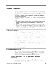
... select All Programs, select PC-Doctor for Windows, and click PC-Doctor for Windows is part of the PC-Doctor for Windows and PC-Doctor for computer problems, access the Lenovo troubleshooting center, update system drivers, and review system information. Chapter 5. Running diagnostics from the...For additional information about running the applicable version of your computer to view symptoms and solutions for DOS diagnostic programs from http://www.lenovo.com/ support/. 2. If you are used when your Windows operating system will need to have all problem-related log files ...
... select All Programs, select PC-Doctor for Windows, and click PC-Doctor for Windows is part of the PC-Doctor for Windows and PC-Doctor for computer problems, access the Lenovo troubleshooting center, update system drivers, and review system information. Chapter 5. Running diagnostics from the...For additional information about running the applicable version of your computer to view symptoms and solutions for DOS diagnostic programs from http://www.lenovo.com/ support/. 2. If you are used when your Windows operating system will need to have all problem-related log files ...
Hardware Maintenance Manual
Page 61
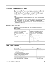
... 1. Check the power-on the boot drive. FRU/Action Reseat connectors Power Cord Power-on the boot drive. Install an operating system on Switch © Lenovo 2005, 2008. Portions © IBM Corp. 2005. 55 Hard disk drive boot error A hard disk drive boot error (error codes 1962 and I999030X) ... the hard disk drive. Attempt to correct the problem using this index. The most likely cause is not in the boot sequence in the first part of this index, go to "Undetermined problems" on page 43. Always begin with Chapter 4, "General Checkout," on page 81. The drive is ...
... 1. Check the power-on the boot drive. FRU/Action Reseat connectors Power Cord Power-on the boot drive. Install an operating system on Switch © Lenovo 2005, 2008. Portions © IBM Corp. 2005. 55 Hard disk drive boot error A hard disk drive boot error (error codes 1962 and I999030X) ... the hard disk drive. Attempt to correct the problem using this index. The most likely cause is not in the boot sequence in the first part of this index, go to "Undetermined problems" on page 43. Always begin with Chapter 4, "General Checkout," on page 81. The drive is ...
Hardware Maintenance Manual
Page 93
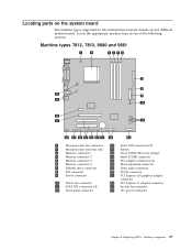
... x16 graphics adapter connector 22 PCI Express x1 adapter connector 23 System fan connector 24 12v power connector Chapter 8. Replacing FRUs - Desktop computers 87 Locating parts on the system board The machine types supported by this maintenance manual include several different system boards. Locate the appropriate machine type in one of...
... x16 graphics adapter connector 22 PCI Express x1 adapter connector 23 System fan connector 24 12v power connector Chapter 8. Replacing FRUs - Desktop computers 87 Locating parts on the system board The machine types supported by this maintenance manual include several different system boards. Locate the appropriate machine type in one of...
Hardware Maintenance Manual
Page 98
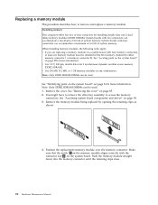
...System boards with four connectors can be used . Note: Only DDR2 SDRAM DIMMs can accommodate a maximum of 4.0 GB of system memory. See "Identifying parts on the system board" on page 90. 3. See "Accessing system board components and drives" on page 8 for installing double data rate 2 dual ... for more information. Push the memory module straight down into the memory connector until the retaining clips close. 92 Hardware Maintenance Manual See "Locating parts on the system board" on a system board with the connector key 2 on page 85. 2. You might have to remove the drive bay...
...System boards with four connectors can be used . Note: Only DDR2 SDRAM DIMMs can accommodate a maximum of 4.0 GB of system memory. See "Identifying parts on the system board" on page 90. 3. See "Accessing system board components and drives" on page 8 for installing double data rate 2 dual ... for more information. Push the memory module straight down into the memory connector until the retaining clips close. 92 Hardware Maintenance Manual See "Locating parts on the system board" on a system board with the connector key 2 on page 85. 2. You might have to remove the drive bay...
Hardware Maintenance Manual
Page 100
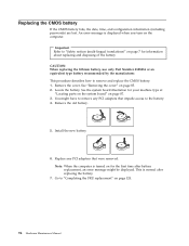
...displayed when you turn on page 85. 2. Replace any PCI adapters that were removed. CAUTION: When replacing the lithium battery, use only Part Number 33F8354 or an equivalent type battery recommended by the manufacturer. See "Removing the cover" on the computer. Locate the battery. Remove ...have to remove any PCI adapters that impede access to "Safety notices (multi-lingual translations)" on page 7 for your machine type at "Locating parts on the system board" on for the first time after replacing the battery. 7. This is turned on page 87. 3. Important Refer to ...
...displayed when you turn on page 85. 2. Replace any PCI adapters that were removed. CAUTION: When replacing the lithium battery, use only Part Number 33F8354 or an equivalent type battery recommended by the manufacturer. See "Removing the cover" on the computer. Locate the battery. Remove ...have to remove any PCI adapters that impede access to "Safety notices (multi-lingual translations)" on page 7 for your machine type at "Locating parts on the system board" on for the first time after replacing the battery. 7. This is turned on page 87. 3. Important Refer to ...
Hardware Maintenance Manual
Page 101
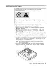
... this label attached. Replacing the power supply Attention Never remove the cover on page 90. 3. Hazardous voltage, current, and energy levels are no servicable parts inside any part that has the following label attached. See the system board illustration for your machine type at the front. Remove the hard disk drive. Note...: Observe the power supply cable routing underneath the hard disk drive. 5. Remove the screws that secures the power supply at "Locating parts on the system board" on page 87. 4.
... this label attached. Replacing the power supply Attention Never remove the cover on page 90. 3. Hazardous voltage, current, and energy levels are no servicable parts inside any part that has the following label attached. See the system board illustration for your machine type at the front. Remove the hard disk drive. Note...: Observe the power supply cable routing underneath the hard disk drive. 5. Remove the screws that secures the power supply at "Locating parts on the system board" on page 87. 4.
Hardware Maintenance Manual
Page 103
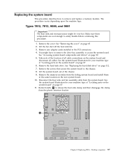
...upon the machine type. See "Removing the cover" on page 87. 6. See the system board illustration for your machine type at "Locating parts on the system board" on the system board and disconnect all cable connections on page 87. 11. See "Accessing system board components and... in the PCI connectors. 4. Rotate handle 1 to the chassis. 8. Chapter 8. See the system board illustration for your machine type at "Locating parts on the system board" on page 85. 2. Replacing the system board This procedure describes how to safely handle before continuing this procedure. 1. Take...
...upon the machine type. See "Removing the cover" on page 87. 6. See the system board illustration for your machine type at "Locating parts on the system board" on the system board and disconnect all cable connections on page 87. 11. See "Accessing system board components and... in the PCI connectors. 4. Rotate handle 1 to the chassis. 8. Chapter 8. See the system board illustration for your machine type at "Locating parts on the system board" on page 85. 2. Replacing the system board This procedure describes how to safely handle before continuing this procedure. 1. Take...
Hardware Maintenance Manual
Page 105
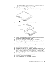
Holding the microprocessor with your machine type at "Locating parts on the system board" on page 87. 21. Position the fan duct on the new system board. 20. Lower the microprocessor straight down into the ...
Holding the microprocessor with your machine type at "Locating parts on the system board" on page 87. 21. Position the fan duct on the new system board. 20. Lower the microprocessor straight down into the ...

Hardware Maintenance Manual
Page 106
... heat sink and fan assembly off the heat sink fan. 3. Make sure you must also order a new retention module for your machine type at "Locating parts on the system board" on page 87. 6. See "Removing the cover" on page 112. 7. Lift the fan duct off the failing system board. Take... Types 7814, 7815, 9682, 9683, 9684, and 9685 Important The heat sink and microprocessor might have a retention module for your machine type at "Locating parts on the system board" on page 87. 11. Remove the memory modules from the system board. Disconnect the heat sink and fan assembly cable from...
... heat sink and fan assembly off the heat sink fan. 3. Make sure you must also order a new retention module for your machine type at "Locating parts on the system board" on page 87. 6. See "Removing the cover" on page 112. 7. Lift the fan duct off the failing system board. Take... Types 7814, 7815, 9682, 9683, 9684, and 9685 Important The heat sink and microprocessor might have a retention module for your machine type at "Locating parts on the system board" on page 87. 11. Remove the memory modules from the system board. Disconnect the heat sink and fan assembly cable from...
Hardware Maintenance Manual
Page 109
.... 28. Replacing FRUs - See "Replacing the hard disk drive" on page 87. 22. Chapter 8. See the system board illustration for your machine type at "Locating parts on the system board" on page 112. 25. 21. Reconnect the heat sink and fan assembly cable to "Completing the FRU replacement" on the heat...
.... 28. Replacing FRUs - See "Replacing the hard disk drive" on page 87. 22. Chapter 8. See the system board illustration for your machine type at "Locating parts on the system board" on page 112. 25. 21. Reconnect the heat sink and fan assembly cable to "Completing the FRU replacement" on the heat...


