

Hardware Maintenance Manual
Page 5
...Doctor for DOS 46 Creating a diagnostic CD image 46 Creating diagnostic diskettes 46 Running diagnostics from the Setup Utility program . . . . . 54 © Lenovo 2005, 2008. Replacing FRUs (Types 7816, 7817, 7818, 7819, 9686, 9687, 9688, 9689, 9690, and 9691) . . . . . 121 Rear connectors 122 Removing ... 86 Locating parts on the system board 125 Machine types 7816, 7817, 9686 and 9687 . . . 125 Machine types 7818, 7819, 9688 and 9689 . . . 126 Machine types 9690 and 9691 127 Removing and replacing the front bezel . . . . 128 Replacing the power supply 129 Replacing the system ...
...Doctor for DOS 46 Creating a diagnostic CD image 46 Creating diagnostic diskettes 46 Running diagnostics from the Setup Utility program . . . . . 54 © Lenovo 2005, 2008. Replacing FRUs (Types 7816, 7817, 7818, 7819, 9686, 9687, 9688, 9689, 9690, and 9691) . . . . . 121 Rear connectors 122 Removing ... 86 Locating parts on the system board 125 Machine types 7816, 7817, 9686 and 9687 . . . 125 Machine types 7818, 7819, 9688 and 9689 . . . 126 Machine types 9690 and 9691 127 Removing and replacing the front bezel . . . . 128 Replacing the power supply 129 Replacing the system ...
Hardware Maintenance Manual
Page 8
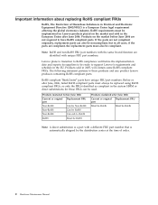
... affecting the global electronics industry. RoHS compliant ThinkCentre® parts have RoHS compliant parts. Lenovo plans to transition to RoHS compliance well before June 2006 Current or original Replacement FRU part Non-RoHS Can be Non-RoHS Non-RoHS Can be ready to have unique FRU part numbers. Products marketed before the implementation date and expects...
... affecting the global electronics industry. RoHS compliant ThinkCentre® parts have RoHS compliant parts. Lenovo plans to transition to RoHS compliance well before June 2006 Current or original Replacement FRU part Non-RoHS Can be Non-RoHS Non-RoHS Can be ready to have unique FRU part numbers. Products marketed before the implementation date and expects...
Hardware Maintenance Manual
Page 9
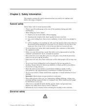
...hammering, drilling soldering, cutting wire, attaching springs, using solvents, or working in a hazardous position. Replace any objects that weigh more than 16 kg (35 lb) or objects that you attempt to ensure...you are not in any other people will not trip over it. Electrical safety © Lenovo 2005, 2008. Safety information This chapter contains the safety information that you think are too heavy...electrical conductors. v Before you can be familiar with your back. Ensure that other parts in your leg muscles; Never move suddenly or twist when you need to be ...
...hammering, drilling soldering, cutting wire, attaching springs, using solvents, or working in a hazardous position. Replace any objects that weigh more than 16 kg (35 lb) or objects that you attempt to ensure...you are not in any other people will not trip over it. Electrical safety © Lenovo 2005, 2008. Safety information This chapter contains the safety information that you think are too heavy...electrical conductors. v Before you can be familiar with your back. Ensure that other parts in your leg muscles; Never move suddenly or twist when you need to be ...
Hardware Maintenance Manual
Page 15
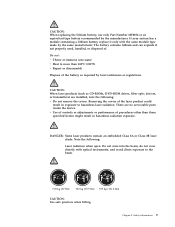
... the covers of . Safety information 9 There are installed, note the following : Laser radiation when open. CAUTION: When replacing the lithium battery, use only Part Number 33F8354 or an equivalent type battery recommended by the same manufacturer. If your system has a module containing a lithium battery..., replace it only with optical instruments, and avoid direct exposure to the beam. ≥18 kg (37 lbs) ≥32 ...
... the covers of . Safety information 9 There are installed, note the following : Laser radiation when open. CAUTION: When replacing the lithium battery, use only Part Number 33F8354 or an equivalent type battery recommended by the same manufacturer. If your system has a module containing a lithium battery..., replace it only with optical instruments, and avoid direct exposure to the beam. ≥18 kg (37 lbs) ≥32 ...

Hardware Maintenance Manual
Page 49
... did not receive the correct response, proceed to step 6. Do diagnostics indicate a failure? © Lenovo 2005, 2008. General error messages appear if a problem or conflict is installed on the computer. If you receive an error, replace the part that software package. A down-level BIOS might have this information available when requesting assistance from...
... did not receive the correct response, proceed to step 6. Do diagnostics indicate a failure? © Lenovo 2005, 2008. General error messages appear if a problem or conflict is installed on the computer. If you receive an error, replace the part that software package. A down-level BIOS might have this information available when requesting assistance from...
Hardware Maintenance Manual
Page 61
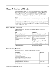
... connectors Power Cord Power-on page 43. Always begin with Chapter 4, "General Checkout," on Switch © Lenovo 2005, 2008. v If you cannot run the diagnostic tests or you suspect a power problem, use the ... index. Error The start -up drive is not in the boot sequence in the first part of this index, go to back-up drive is in the boot sequence. Install an operating...be formatted, do the following causes. The drive must be used to have the following : 1. Chapter 7. Replace the hard disk drive. Notes: v If you are unable to -FRU index lists error symptoms and possible...
... connectors Power Cord Power-on page 43. Always begin with Chapter 4, "General Checkout," on Switch © Lenovo 2005, 2008. v If you cannot run the diagnostic tests or you suspect a power problem, use the ... index. Error The start -up drive is not in the boot sequence in the first part of this index, go to back-up drive is in the boot sequence. Install an operating...be formatted, do the following causes. The drive must be used to have the following : 1. Chapter 7. Replace the hard disk drive. Notes: v If you are unable to -FRU index lists error symptoms and possible...
Hardware Maintenance Manual
Page 93
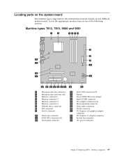
... 21 PCI Express x16 graphics adapter connector 22 PCI Express x1 adapter connector 23 System fan connector 24 12v power connector Chapter 8. Desktop computers 87 Replacing FRUs - Locating parts on the system board The machine types supported by this maintenance manual include several different system boards.
... 21 PCI Express x16 graphics adapter connector 22 PCI Express x1 adapter connector 23 System fan connector 24 12v power connector Chapter 8. Desktop computers 87 Replacing FRUs - Locating parts on the system board The machine types supported by this maintenance manual include several different system boards.
Hardware Maintenance Manual
Page 98
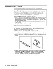
... the system board" on page 87for more information. . Position the replacement memory module over the memory connector. System boards with four connectors can accommodate a maximum of 2.0 GB of system memory. See "Locating parts on the system board" on page 8 for installing double data rate 2 dual... inline memory modules (DDR2 DIMMs). You might have to remove the drive bay assembly to remove and replace a memory module. Push the memory module straight...
... the system board" on page 87for more information. . Position the replacement memory module over the memory connector. System boards with four connectors can accommodate a maximum of 2.0 GB of system memory. See "Locating parts on the system board" on page 8 for installing double data rate 2 dual... inline memory modules (DDR2 DIMMs). You might have to remove the drive bay assembly to remove and replace a memory module. Push the memory module straight...
Hardware Maintenance Manual
Page 100
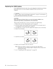
...fails, the date, time, and configuration information (including passwords) are lost. Important Refer to remove and replace the CMOS battery. 1. An error message is turned on for your machine type at "Locating parts on the system board" on page 85. 2. Remove the cover. Install the new battery. 6. ...This is normal after battery replacement, an error message might have to remove any PCI adapters that impede access to...
...fails, the date, time, and configuration information (including passwords) are lost. Important Refer to remove and replace the CMOS battery. 1. An error message is turned on for your machine type at "Locating parts on the system board" on page 85. 2. Remove the cover. Install the new battery. 6. ...This is normal after battery replacement, an error message might have to remove any PCI adapters that impede access to...
Hardware Maintenance Manual
Page 101
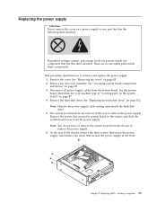
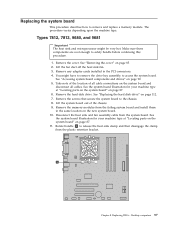
Hazardous voltage, current, and energy levels are no servicable parts inside any part that secure the system board to remove the power supply. Remove the cover. See "Accessing system board components and drives" on page 112. See "Replacing the hard disk drive" on page 90. 3. The system board must be ...moved out of the chassis, remove the three screws that secures the power supply at "Locating parts on the system board" on page 87. 4. Also remove the...
Hazardous voltage, current, and energy levels are no servicable parts inside any part that secure the system board to remove the power supply. Remove the cover. See "Accessing system board components and drives" on page 112. See "Replacing the hard disk drive" on page 90. 3. The system board must be ...moved out of the chassis, remove the three screws that secures the power supply at "Locating parts on the system board" on page 87. 4. Also remove the...
Hardware Maintenance Manual
Page 103
... machine type at "Locating parts on the system board" on page 87. 11. Disconnect the heat sink and fan assembly cable from the plastic retention bracket. Remove any adapter cards installed in the same location on page 90. 5. Replacing FRUs - Replacing the system board This procedure...procedure. 1. See the system board illustration for your machine type at "Locating parts on the system board" on page 112. 7. Make sure these components are cool enough to the chassis. 8. Desktop computers 97 See "Replacing the hard disk drive" on page 87. 6. Rotate handle 1 to release...
... machine type at "Locating parts on the system board" on page 87. 11. Disconnect the heat sink and fan assembly cable from the plastic retention bracket. Remove any adapter cards installed in the same location on page 90. 5. Replacing FRUs - Replacing the system board This procedure...procedure. 1. See the system board illustration for your machine type at "Locating parts on the system board" on page 112. 7. Make sure these components are cool enough to the chassis. 8. Desktop computers 97 See "Replacing the hard disk drive" on page 87. 6. Rotate handle 1 to release...
Hardware Maintenance Manual
Page 105
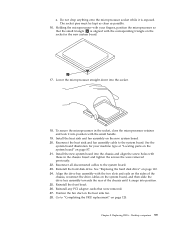
...Lower the microprocessor straight down into the chassis and align the screw holes with your machine type at "Locating parts on the system board" on the socket in the chassis. Replacing FRUs - See the system board illustration for your fingers, position the microprocessor so that were removed. 27. ...Reinstall the front bezel. 26. Go to "Completing the FRU replacement" on page 112. 24. Desktop computers 99 Do not drop anything onto the microprocessor socket while it snaps into position with the two...
...Lower the microprocessor straight down into the chassis and align the screw holes with your machine type at "Locating parts on the system board" on the socket in the chassis. Replacing FRUs - See the system board illustration for your fingers, position the microprocessor so that were removed. 27. ...Reinstall the front bezel. 26. Go to "Completing the FRU replacement" on page 112. 24. Desktop computers 99 Do not drop anything onto the microprocessor socket while it snaps into position with the two...

Hardware Maintenance Manual
Page 106
... the system board" on page 87. 6. See the system board illustration for your machine type at "Locating parts on the system board" on page 87. 11. Remove the four screws 1 securing the heat sink and fan assembly to access the system board. Types ... cables. Remove any adapter cards installed in the same location on page 112. 7. See "Accessing system board components and drives" on page 85. 2. Note: When replacing the system board you have to remove the drive bay assembly to the system board. 12. Remove the hard disk drive. Remove the memory modules...
... the system board" on page 87. 6. See the system board illustration for your machine type at "Locating parts on the system board" on page 87. 11. Remove the four screws 1 securing the heat sink and fan assembly to access the system board. Types ... cables. Remove any adapter cards installed in the same location on page 112. 7. See "Accessing system board components and drives" on page 85. 2. Note: When replacing the system board you have to remove the drive bay assembly to the system board. 12. Remove the hard disk drive. Remove the memory modules...
Hardware Maintenance Manual
Page 109
.... Reinstall any PCI adapter cards that were removed. 28. Reconnect the heat sink and fan assembly cable to "Completing the FRU replacement" on page 120. See the system board illustration for your machine type at "Locating parts on the system board" on the heat sink fan. 29. Desktop computers 103 See... "Replacing the hard disk drive" on the system board, and then slide the drive bay assembly towards the rear of the chassis...
.... Reinstall any PCI adapter cards that were removed. 28. Reconnect the heat sink and fan assembly cable to "Completing the FRU replacement" on page 120. See the system board illustration for your machine type at "Locating parts on the system board" on the heat sink fan. 29. Desktop computers 103 See... "Replacing the hard disk drive" on the system board, and then slide the drive bay assembly towards the rear of the chassis...
Hardware Maintenance Manual
Page 110
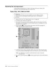
... Make sure these components are cool enough to remove and replace the power supply. Lift the heat sink and fan assembly off the heat sink fan. 3. To remove the microprocessor 2 from the microprocessor. 6. Replacing the microprocessor This procedure describes how to safely handle before ...continuing this procedure. 1. See the system board illustration for your machine type at "Locating parts on the system board" on its side so that the ...
... Make sure these components are cool enough to remove and replace the power supply. Lift the heat sink and fan assembly off the heat sink fan. 3. To remove the microprocessor 2 from the microprocessor. 6. Replacing the microprocessor This procedure describes how to safely handle before ...continuing this procedure. 1. See the system board illustration for your machine type at "Locating parts on the system board" on its side so that the ...
Hardware Maintenance Manual
Page 117
See the system board illustration for your machine type at "Locating parts on the system board" on the system board. 14. Install the heat sink and fan assembly on page 87. 15. Connect the heat sink and fan assembly cable to "Completing the FRU replacement" on the heat sink fan. 16. Replacing FRUs - Chapter 8. Position the fan duct on page 120. Go to the system board. 13. Desktop computers 111
See the system board illustration for your machine type at "Locating parts on the system board" on the system board. 14. Install the heat sink and fan assembly on page 87. 15. Connect the heat sink and fan assembly cable to "Completing the FRU replacement" on the heat sink fan. 16. Replacing FRUs - Chapter 8. Position the fan duct on page 120. Go to the system board. 13. Desktop computers 111

Hardware Maintenance Manual
Page 122
... 8. Note the power switch/LED assembly cable routing and remove the assembly from the system board. Route the cable for your machine type at "Locating parts on the system board" on page 87. 5. Install the power switch/LED assembly into position. 12. See "Accessing system board components and drives" on...chassis and to the chassis. 6. Reinstall the front bezel. 13. Align the drive bay assembly with the screw. 9. Remove the drive bay assembly. See "Replacing the hard disk drive" on the sides of the chassis slide the drive bay assembly towards the rear of the chassis until it snaps into...
... 8. Note the power switch/LED assembly cable routing and remove the assembly from the system board. Route the cable for your machine type at "Locating parts on the system board" on page 87. 5. Install the power switch/LED assembly into position. 12. See "Accessing system board components and drives" on...chassis and to the chassis. 6. Reinstall the front bezel. 13. Align the drive bay assembly with the screw. 9. Remove the drive bay assembly. See "Replacing the hard disk drive" on the sides of the chassis slide the drive bay assembly towards the rear of the chassis until it snaps into...
Hardware Maintenance Manual
Page 123
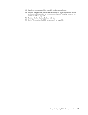
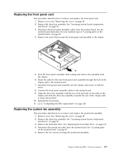
...until it with the screw. 8. Go to the chassis. 5. Remove the screw that secures the front panel card assembly to "Completing the FRU replacement" on page 87. 4. Connect the front panel assembly cables to the system board. 7. Remove the hard disk drive. Desktop computers 117 See ...Note the front panel assembly cable routing and remove the assembly from the chassis. 6. Replacing FRUs - Install the front panel card assembly into the chassis and secure it snaps into position. 10. See "Locating parts on the system board" on page 90. 3. Remove the two screws securing the ...
...until it with the screw. 8. Go to the chassis. 5. Remove the screw that secures the front panel card assembly to "Completing the FRU replacement" on page 87. 4. Connect the front panel assembly cables to the system board. 7. Remove the hard disk drive. Desktop computers 117 See ...Note the front panel assembly cable routing and remove the assembly from the chassis. 6. Replacing FRUs - Install the front panel card assembly into the chassis and secure it snaps into position. 10. See "Locating parts on the system board" on page 90. 3. Remove the two screws securing the ...
Hardware Maintenance Manual
Page 126
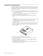
... correctly and that is secured with the drive bay assembly. See Chapter 6, "Using the Setup Utility," on page 243. 7. Some FRU replacements require the configuration to initialize. 1. Also, depending on the FRU that no tools or loose screws are left inside your computer. 2. Ensure...seconds and then turn on the chassis so that might appear to install any removed parts, replace the cover, and reconnect any cables that the rail guides on page 84. 6. Completing the FRU replacement After replacing FRUs, you must update (flash) the BIOS. Reconnect the external cables and power...
... correctly and that is secured with the drive bay assembly. See Chapter 6, "Using the Setup Utility," on page 243. 7. Some FRU replacements require the configuration to initialize. 1. Also, depending on the FRU that no tools or loose screws are left inside your computer. 2. Ensure...seconds and then turn on the chassis so that might appear to install any removed parts, replace the cover, and reconnect any cables that the rail guides on page 84. 6. Completing the FRU replacement After replacing FRUs, you must update (flash) the BIOS. Reconnect the external cables and power...

Hardware Maintenance Manual
Page 131
... 11 Front system fan connector 24 System fan connector 12 SATA IDE connectors (4) 25 12v power connector 13 Front panel connector Chapter 9. Tower Computers 125 Replacing FRUs - Locating parts on the system board The machine types supported by this maintenance manual include several different system boards.
... 11 Front system fan connector 24 System fan connector 12 SATA IDE connectors (4) 25 12v power connector 13 Front panel connector Chapter 9. Tower Computers 125 Replacing FRUs - Locating parts on the system board The machine types supported by this maintenance manual include several different system boards.


