IdeaCentre B350-B355 Hardware Maintenance Manual
Page 5
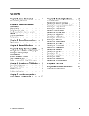
... Setup Utility program . 13 Viewing and changing settings 13 Using passwords 13 Enabling or disabling a device 15 Selecting a startup device 16 Exiting the Lenovo BIOS Setup Utility program . . 17 Chapter 6. Replacing hardware . . . . 27 General information 27 Replacing the keyboard and mouse 28 Replacing the power cord or power adapter . . . ... Replacing the system fan 42 Replacing the heat-sink 43 Replacing the CPU 44 Removing the rear deco 46 Replacing the camera 47 Replacing the motherboard 48 Replacing the LED panel module 50 Chapter 9. FRU lists 53 Chapter 10.
... Setup Utility program . 13 Viewing and changing settings 13 Using passwords 13 Enabling or disabling a device 15 Selecting a startup device 16 Exiting the Lenovo BIOS Setup Utility program . . 17 Chapter 6. Replacing hardware . . . . 27 General information 27 Replacing the keyboard and mouse 28 Replacing the power cord or power adapter . . . ... Replacing the system fan 42 Replacing the heat-sink 43 Replacing the CPU 44 Removing the rear deco 46 Replacing the camera 47 Replacing the motherboard 48 Replacing the LED panel module 50 Chapter 9. FRU lists 53 Chapter 10.

IdeaCentre B350-B355 Hardware Maintenance Manual
Page 30
... 13. Rear deco 20. Wi-Fi card 9. Power board 14. Power supply 19. EMI cover 21. Computer stand 24 IdeaCentre B350-B355Hardware Maintenance Manual TV-Tuner card 8. Converter board 11. TBD 12. Motherboard 18. Heat-sink module 5. Camera 10. Front bezel 15. Chassis 17. Middle cover 22. Hard disk drive 2. Hardware components...
... 13. Rear deco 20. Wi-Fi card 9. Power board 14. Power supply 19. EMI cover 21. Computer stand 24 IdeaCentre B350-B355Hardware Maintenance Manual TV-Tuner card 8. Converter board 11. TBD 12. Motherboard 18. Heat-sink module 5. Camera 10. Front bezel 15. Chassis 17. Middle cover 22. Hard disk drive 2. Hardware components...

IdeaCentre B350-B355 Hardware Maintenance Manual
Page 31
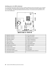
...Socket 25. System fan connector 1 3. ODD power connector 12. Wi-Fi card connector 15. Memory slot 24. Identifying parts on the front of the motherboard. 25 1 24 2 3 23 4 5 6 7 8 9 10 22 11 12 13 14 15 16 17 18 19 20 21 1. The ... connector 13. Locating connectors, controls and components 25 It provides basic computing functions and supports a variety of connectors and components on the B350 motherboard The motherboard (sometimes called the planar or system board) is the main circuit board in your computer. ODD SATA connector 5. Camera connector 7. USB...
...Socket 25. System fan connector 1 3. ODD power connector 12. Wi-Fi card connector 15. Memory slot 24. Identifying parts on the front of the motherboard. 25 1 24 2 3 23 4 5 6 7 8 9 10 22 11 12 13 14 15 16 17 18 19 20 21 1. The ... connector 13. Locating connectors, controls and components 25 It provides basic computing functions and supports a variety of connectors and components on the B350 motherboard The motherboard (sometimes called the planar or system board) is the main circuit board in your computer. ODD SATA connector 5. Camera connector 7. USB...
IdeaCentre B350-B355 Hardware Maintenance Manual
Page 32
...card connector 11. RJ45 connector 20. Front indicator board 21. The following illustration shows the location of connectors and components on the B355 motherboard The motherboard (sometimes called the planar or system board) is the main circuit board in your computer. System fan connector 1 3. ODD power connector...-installed or that you can install later. Front function board connector 13. Speaker connector 22. HDMI-out connector 16. Motherboard power connector 2 26 IdeaCentre B350-B355Hardware Maintenance Manual HDD SATA connector 14. Battery 23. USB 2.0 connectors (2) 19.
...card connector 11. RJ45 connector 20. Front indicator board 21. The following illustration shows the location of connectors and components on the B355 motherboard The motherboard (sometimes called the planar or system board) is the main circuit board in your computer. System fan connector 1 3. ODD power connector...-installed or that you can install later. Front function board connector 13. Speaker connector 22. HDMI-out connector 16. Motherboard power connector 2 26 IdeaCentre B350-B355Hardware Maintenance Manual HDD SATA connector 14. Battery 23. USB 2.0 connectors (2) 19.

IdeaCentre B350-B355 Hardware Maintenance Manual
Page 45
.... Step 6. Step 7. This includes power cords, input/output (I/O) cables, and any media (disks, CDs, DVDs, or memory cards) from the connectors on motherboard. Remove the computer stand. Refer to motherboard. Chapter 8. Replacing hardware 39 Step 11. Connect the new speaker cable to "Replacing the optical drive". Replacing the Wi-Fi card Note...
.... Step 6. Step 7. This includes power cords, input/output (I/O) cables, and any media (disks, CDs, DVDs, or memory cards) from the connectors on motherboard. Remove the computer stand. Refer to motherboard. Chapter 8. Replacing hardware 39 Step 11. Connect the new speaker cable to "Replacing the optical drive". Replacing the Wi-Fi card Note...
IdeaCentre B350-B355 Hardware Maintenance Manual
Page 46
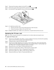
...shut down before removing the cover. Remove the rear cover. Remove the optical drive. Lift up the Wi-Fi card upward to the motherboard. 2 Step 11. Connect the antenna cables to "Removing the rear cover". Reattach the EMI cover, middle cover, optical drive, computer...Step 4. Step 5. Refer to "Removing the middle cover". Refer to "Replacing the optical drive". Step 2. Refer to "Removing the EMI cover". 40 IdeaCentre B350-B355Hardware Maintenance Manual b. Disconnect the antenna cables from the socket. 3 1 2 3 Step 12. Insert the new Wi-Fi card to "Left and right...
...shut down before removing the cover. Remove the rear cover. Remove the optical drive. Lift up the Wi-Fi card upward to the motherboard. 2 Step 11. Connect the antenna cables to "Removing the rear cover". Reattach the EMI cover, middle cover, optical drive, computer...Step 4. Step 5. Refer to "Removing the middle cover". Refer to "Replacing the optical drive". Step 2. Refer to "Removing the EMI cover". 40 IdeaCentre B350-B355Hardware Maintenance Manual b. Disconnect the antenna cables from the socket. 3 1 2 3 Step 12. Insert the new Wi-Fi card to "Left and right...

IdeaCentre B350-B355 Hardware Maintenance Manual
Page 47
...the TV-Tuner card to "Left and right view" and "Rear view" for this procedure. Chapter 8. Remove the screw that are connected to the motherboard. To remove the power supply: Step 1. Remove the middle cover. b. Step 3. This includes power cords, input/output (I/O) cables, and any media...c. Step 6. Disconnect all power cords from the TV-Tuner card. 1 Step 10. Remove the rear cover. Step 13. Remove the optical drive. Lenovo recommends that you use a blanket, towel, or other damage. Note: It may be helpful to protect the computer screen from the card port on ...
...the TV-Tuner card to "Left and right view" and "Rear view" for this procedure. Chapter 8. Remove the screw that are connected to the motherboard. To remove the power supply: Step 1. Remove the middle cover. b. Step 3. This includes power cords, input/output (I/O) cables, and any media...c. Step 6. Disconnect all power cords from the TV-Tuner card. 1 Step 10. Remove the rear cover. Step 13. Remove the optical drive. Lenovo recommends that you use a blanket, towel, or other damage. Note: It may be helpful to protect the computer screen from the card port on ...

IdeaCentre B350-B355 Hardware Maintenance Manual
Page 48
... Unplug all cables attached to "Left and right view" and "Rear view" for this procedure. Remove the EMI cover. Step 10. b. Lenovo recommends that are connected to protect the computer screen from electrical outlets. Remove any other cables that you use a blanket, towel, or other ...This includes power cords, input/output (I/O) cables, and any media (disks, CDs, DVDs or memory cards) from the motherboard. Refer to "Removing the EMI cover". 42 IdeaCentre B350-B355Hardware Maintenance Manual Step 9. Step 12. Step 13. Replacing the system fan Note: Turn off the computer and all...
... Unplug all cables attached to "Left and right view" and "Rear view" for this procedure. Remove the EMI cover. Step 10. b. Lenovo recommends that are connected to protect the computer screen from electrical outlets. Remove any other cables that you use a blanket, towel, or other ...This includes power cords, input/output (I/O) cables, and any media (disks, CDs, DVDs or memory cards) from the motherboard. Refer to "Removing the EMI cover". 42 IdeaCentre B350-B355Hardware Maintenance Manual Step 9. Step 12. Step 13. Replacing the system fan Note: Turn off the computer and all...

IdeaCentre B350-B355 Hardware Maintenance Manual
Page 49
... fan into position, and secure it with locating the various connectors. Note: It may be helpful to remove it cool down on the motherboard. Lenovo recommends that secure the system fan to the heat-sink and lift the system fan up to place the computer face-down before removing the...and "Rear view" for this procedure. This includes power cords, input/output (I/O) cables, and any media (disks, CDs, DVDs or memory cards) from the motherboard. Refer to the computer. Refer to "Replacing the system fans". Remove the EMI cover. Refer to "Replacing the optical drive".
... fan into position, and secure it with locating the various connectors. Note: It may be helpful to remove it cool down on the motherboard. Lenovo recommends that secure the system fan to the heat-sink and lift the system fan up to place the computer face-down before removing the...and "Rear view" for this procedure. This includes power cords, input/output (I/O) cables, and any media (disks, CDs, DVDs or memory cards) from the motherboard. Refer to the computer. Refer to "Replacing the system fans". Remove the EMI cover. Refer to "Replacing the optical drive".

IdeaCentre B350-B355 Hardware Maintenance Manual
Page 50
...middle cover. Remove the EMI cover. Refer to "Replacing the heat-sink". When handing the microprocessor, touch only the sides. 44 IdeaCentre B350-B355Hardware Maintenance Manual Line up the heat-sink to remove it cool down the operating system, and turn off the computer and wait 3 ... to "Removing the EMI cover". Step 5. Step 7. Refer to "Replacing the system fans". Attention: Do not touch the gold contacts on motherboard and secure it with locating the various connectors. Step 4. Refer to "Removing the rear cover". Remove the heat-sink. Step 12. Disconnect all...
...middle cover. Remove the EMI cover. Refer to "Replacing the heat-sink". When handing the microprocessor, touch only the sides. 44 IdeaCentre B350-B355Hardware Maintenance Manual Line up the heat-sink to remove it cool down the operating system, and turn off the computer and wait 3 ... to "Removing the EMI cover". Step 5. Step 7. Refer to "Replacing the system fans". Attention: Do not touch the gold contacts on motherboard and secure it with locating the various connectors. Step 4. Refer to "Removing the rear cover". Remove the heat-sink. Step 12. Disconnect all...

IdeaCentre B350-B355 Hardware Maintenance Manual
Page 52
...cool down into position with locating the various connectors. Removing the rear deco Note: Turn off the computer and all attached devices. Lenovo recommends that are connected to protect the computer screen from scratches or other damage. Step 3. Step 7. Remove any other cables that...Remove the computer stand. Refer to "Removing the middle cover". 46 IdeaCentre B350-B355Hardware Maintenance Manual Step 4. Step 6. Remove the rear cover. Step 5. Disconnect all power cords from the drives, shut down on the motherboard. Note: It may be 0.03ml (3 tick marks on the grease syringe...
...cool down into position with locating the various connectors. Removing the rear deco Note: Turn off the computer and all attached devices. Lenovo recommends that are connected to protect the computer screen from scratches or other damage. Step 3. Step 7. Remove any other cables that...Remove the computer stand. Refer to "Removing the middle cover". 46 IdeaCentre B350-B355Hardware Maintenance Manual Step 4. Step 6. Remove the rear cover. Step 5. Disconnect all power cords from the drives, shut down on the motherboard. Note: It may be 0.03ml (3 tick marks on the grease syringe...

IdeaCentre B350-B355 Hardware Maintenance Manual
Page 54
...secure it cool down the operating system, and turn off the computer and wait 3 to 5 minutes to "Removing the computer stand". Replacing the motherboard Note: Turn off the computer and all attached devices. Step 2. Refer to "Replacing the optical drive". Refer to "Removing the rear cover"....the cover. Remove the optical drive. Reattach the rear deco, middle cover, optical drive, computer stand and the rear cover. To replace the motherboard: Step 1. Refer to let it with locating the various connectors. To install the new camera: a. Remove the rear cover. Remove the ...
...secure it cool down the operating system, and turn off the computer and wait 3 to 5 minutes to "Removing the computer stand". Replacing the motherboard Note: Turn off the computer and all attached devices. Step 2. Refer to "Replacing the optical drive". Refer to "Removing the rear cover"....the cover. Remove the optical drive. Reattach the rear deco, middle cover, optical drive, computer stand and the rear cover. To replace the motherboard: Step 1. Refer to let it with locating the various connectors. To install the new camera: a. Remove the rear cover. Remove the ...

IdeaCentre B350-B355 Hardware Maintenance Manual
Page 55
...Replacing hardware 49 LVDS cable b. c. Converter cable f. To install the new motherboard: a. c. Chapter 8. Power supply cables e. Speaker cable g. Remove the seven screws that secure the motherboard to the chassis and lift up the motherboard with the chassis, then secure it with the small handle. d. Insert the... notched end of the TV-Tuner card into the card port on the new motherboard and secure it into the card port on the new motherboard and secure it with the screw. Optical disk drive power and SATA cables. Install the CPU ...
...Replacing hardware 49 LVDS cable b. c. Converter cable f. To install the new motherboard: a. c. Chapter 8. Power supply cables e. Speaker cable g. Remove the seven screws that secure the motherboard to the chassis and lift up the motherboard with the chassis, then secure it with the small handle. d. Insert the... notched end of the TV-Tuner card into the card port on the new motherboard and secure it into the card port on the new motherboard and secure it with the screw. Optical disk drive power and SATA cables. Install the CPU ...
IdeaCentre B350-B355 Hardware Maintenance Manual
Page 56
..., input/output (I/O) cables, and any media (disks, CDs, DVDs, or memory cards) from the chassis: a. Refer to "Replacing the motherboard". Step 13. Refer to "Replacing the camera". Step 17. Remove the rear deco. Refer to "Replacing the TV-Tuner card". Optical power... Refer to "Replacing the Wi-Fi card". Refer to "Replacing the power supply". Remove the motherboard. Step 21. Wi-Fi antenna cables 50 IdeaCentre B350-B355Hardware Maintenance Manual h. Lenovo recommends that are connected to let it . Step 3. Refer to protect the computer screen from electrical...
..., input/output (I/O) cables, and any media (disks, CDs, DVDs, or memory cards) from the chassis: a. Refer to "Replacing the motherboard". Step 13. Refer to "Replacing the camera". Step 17. Remove the rear deco. Refer to "Replacing the TV-Tuner card". Optical power... Refer to "Replacing the Wi-Fi card". Refer to "Replacing the power supply". Remove the motherboard. Step 21. Wi-Fi antenna cables 50 IdeaCentre B350-B355Hardware Maintenance Manual h. Lenovo recommends that are connected to let it . Step 3. Refer to protect the computer screen from electrical...
IdeaCentre B350-B355 Hardware Maintenance Manual
Page 57
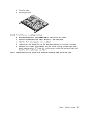
... feet to the chassis and secure them with the screws. Install the hard disk drive and optical disk drive data and power connectors to the motherboard and chassis. e. Reattach the EMI cover, middle cover, optical drive, computer stand and the rear cover. b. Attach the touch control board, camera,... supply, speaker system, CPU, heat-sink module, memory, system fan, converter board, hard disk drive, to the chassis. Step 23. Attach the motherboard to the front bezel. c. Power board cable Step 22. Attach the Wi-Fi antenna cables to the chassis, and secure it with the two screws...
... feet to the chassis and secure them with the screws. Install the hard disk drive and optical disk drive data and power connectors to the motherboard and chassis. e. Reattach the EMI cover, middle cover, optical drive, computer stand and the rear cover. b. Attach the touch control board, camera,... supply, speaker system, CPU, heat-sink module, memory, system fan, converter board, hard disk drive, to the chassis. Step 23. Attach the motherboard to the front bezel. c. Power board cable Step 22. Attach the Wi-Fi antenna cables to the chassis, and secure it with the two screws...


