User Manual
Page 5
... and using rescue media 42 Creating and using a Recovery Repair diskette . . 43 Recovering or installing device drivers . . . . . 44 Setting a rescue device in bay 1 or bay 2 . . . . . 30 Connecting drives 32 Connecting the first optical drive 32 Connecting an additional optical drive, or parallel ATA hard disk drive 32 Connecting a serial ATA hard disk drive. . . . 33 Installing security features 33 Integrated cable lock 34 Padlock 35 Password protection 35 Changing the battery 35 Erasing a lost or forgotten password (clearing CMOS 36 Replacing the cover and connecting the cables...
... and using rescue media 42 Creating and using a Recovery Repair diskette . . 43 Recovering or installing device drivers . . . . . 44 Setting a rescue device in bay 1 or bay 2 . . . . . 30 Connecting drives 32 Connecting the first optical drive 32 Connecting an additional optical drive, or parallel ATA hard disk drive 32 Connecting a serial ATA hard disk drive. . . . 33 Installing security features 33 Integrated cable lock 34 Padlock 35 Password protection 35 Changing the battery 35 Erasing a lost or forgotten password (clearing CMOS 36 Replacing the cover and connecting the cables...

User Manual
Page 9
... let the computer cool before opening the cover. When you unpack an option or CRU, do not open the static-protective package containing the part until the instructions direct you handle options or CRUs, or perform any CRUs, turn off the computer and wait three... seconds. Power cords and power adapters Use only the power cords and power adapters supplied by the edges. v Prevent others from the static-protective packaging and install the part without setting it . When you to a metal expansion-slot cover or other body parts away. v When you install a static-sensitive option or CRU...
... let the computer cool before opening the cover. When you unpack an option or CRU, do not open the static-protective package containing the part until the instructions direct you handle options or CRUs, or perform any CRUs, turn off the computer and wait three... seconds. Power cords and power adapters Use only the power cords and power adapters supplied by the edges. v Prevent others from the static-protective packaging and install the part without setting it . When you to a metal expansion-slot cover or other body parts away. v When you install a static-sensitive option or CRU...
User Manual
Page 15
... attached. Danger Laser radiation when open. There are present inside the CD or DVD drive. Important safety information xiii Removing the covers of the International Electrotechnical Commission (IEC) 60825-1 and CENELEC EN 60 825-1 for Class 1 laser products. Power supply statement Never remove the cover on a power supply or any component that users/installers follow . Elsewhere, these components. Products with optical instruments, and avoid direct exposure...
... attached. Danger Laser radiation when open. There are present inside the CD or DVD drive. Important safety information xiii Removing the covers of the International Electrotechnical Commission (IEC) 60825-1 and CENELEC EN 60 825-1 for Class 1 laser products. Power supply statement Never remove the cover on a power supply or any component that users/installers follow . Elsewhere, these components. Products with optical instruments, and avoid direct exposure...

User Manual
Page 16
...wire 6 3 Antenna discharge unit (NEC 7 Section 810-20) 4 Grounding conductors (NEC Section 810-21 Figure 1. Example of antenna grounding 1 Ground clamp 5 2 Antenna lead-in particular, specifies that the cable ground shall be connected...cable entry as practical. Note to CATV system installer This reminder is provided to call the CATV system installer's attention to the point of the National Electrical Code (NEC) that provides guidelines for the cable Power service grounding electrode system (NEC Article 250, Part H) Ground clamps Electronic service equipment xiv User Guide...
...wire 6 3 Antenna discharge unit (NEC 7 Section 810-20) 4 Grounding conductors (NEC Section 810-21 Figure 1. Example of antenna grounding 1 Ground clamp 5 2 Antenna lead-in particular, specifies that the cable ground shall be connected...cable entry as practical. Note to CATV system installer This reminder is provided to call the CATV system installer's attention to the point of the National Electrical Code (NEC) that provides guidelines for the cable Power service grounding electrode system (NEC Article 250, Part H) Ground clamps Electronic service equipment xiv User Guide...
User Manual
Page 29
... to turn off your computer, always follow the instructions that is provided with your hard disk with antivirus software you time and trouble later: v Create a diagnostic CD image, diagnostic diskettes, or rescue media. Chapter 2. If you need service or technical support, you will save you can cause hardware failures. Updating your computer and report operating-system-controlled settings that you will be asked for Windows PE" on how to open the Start menu from...
... to turn off your computer, always follow the instructions that is provided with your hard disk with antivirus software you time and trouble later: v Create a diagnostic CD image, diagnostic diskettes, or rescue media. Chapter 2. If you need service or technical support, you will save you can cause hardware failures. Updating your computer and report operating-system-controlled settings that you will be asked for Windows PE" on how to open the Start menu from...
User Manual
Page 31
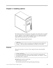
.... System information The following information covers a variety of the computer features and preinstalled software. Installing options This chapter provides an introduction to the Setup Utility program. Chapter 3. You can expand the capabilities of your specific model, refer to the features and options that come with HyperThreading Technology © Lenovo 2006, 2007. Note: Use only parts provided by adding memory, adapters, or drives. Features This section provides...
.... System information The following information covers a variety of the computer features and preinstalled software. Installing options This chapter provides an introduction to the Setup Utility program. Chapter 3. You can expand the capabilities of your specific model, refer to the features and options that come with HyperThreading Technology © Lenovo 2006, 2007. Note: Use only parts provided by adding memory, adapters, or drives. Features This section provides...

User Manual
Page 32
... drive v Serial Advanced Technology Attachment (SATA) internal hard disk drive v Optical drive (some models) Video subsystem PCI Express x16 graphics adapter connector on the system board Audio subsystem v High-definition ADI 1986 Audio Codec v Microphone and headphone connectors on the front panel v Line in, line out, and microphone in connectors on the rear panel v Mono internal speaker (some models) Connectivity v 10/100 Mbps integrated Ethernet controller that support for the Wake on LAN® feature (some models) v 10/100/1000 Mbps integrated Ethernet controller (some models) v PCI...
... drive v Serial Advanced Technology Attachment (SATA) internal hard disk drive v Optical drive (some models) Video subsystem PCI Express x16 graphics adapter connector on the system board Audio subsystem v High-definition ADI 1986 Audio Codec v Microphone and headphone connectors on the front panel v Line in, line out, and microphone in connectors on the rear panel v Mono internal speaker (some models) Connectivity v 10/100 Mbps integrated Ethernet controller that support for the Wake on LAN® feature (some models) v 10/100/1000 Mbps integrated Ethernet controller (some models) v PCI...

User Manual
Page 33
... software. Installing options 13 If it does, an operating system, device drivers to change. Corrections and additions to this publication goes to secure the cover v Startup sequence control v Startup without diskette drive, keyboard, or mouse v Unattended start mode v Diskette and hard disk I/O control v Serial and parallel port I/O control v Security profile by device Preinstalled software Your computer might be identified by model type) Note: Not all countries or regions will have these operating systems. v Microsoft Windows XP Home v Microsoft Windows...
... software. Installing options 13 If it does, an operating system, device drivers to change. Corrections and additions to this publication goes to secure the cover v Startup sequence control v Startup without diskette drive, keyboard, or mouse v Unattended start mode v Diskette and hard disk I/O control v Serial and parallel port I/O control v Security profile by device Preinstalled software Your computer might be identified by model type) Note: Not all countries or regions will have these operating systems. v Microsoft Windows XP Home v Microsoft Windows...
User Manual
Page 50
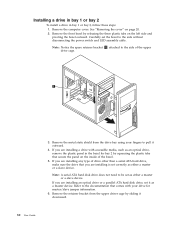
... power switch and LED assembly cable. Note: A serial ATA hard disk drive does not need to pull it downward. 30 User Guide If you are installing any type of drive other than a serial ATA hard drive, make sure the drive that you are installing is set the bezel to the side of the bezel. 5. Refer to the documentation that secure the panel on the inside of the upper drive cage. 3. Carefully set correctly as an optical drive, remove...
... power switch and LED assembly cable. Note: A serial ATA hard disk drive does not need to pull it downward. 30 User Guide If you are installing any type of drive other than a serial ATA hard drive, make sure the drive that you are installing is set the bezel to the side of the bezel. 5. Refer to the documentation that secure the panel on the inside of the upper drive cage. 3. Carefully set correctly as an optical drive, remove...

User Manual
Page 56
.... See "Removing the cover" on page 37. See "Replacing the cover and connecting the cables" on page 20. 3. This is turned on page 22. 4. Erasing a lost or forgotten passwords, see the ThinkVantage Productivity Center program on page 37. 6. Move the jumper from the standard position (pins 1 and 2) to the maintenance or configure position (pins 2 and 3). 5. To change the battery: 1. Install the new battery. 6. Locate the Clear CMOS/Recovery jumper on page 36. 36 User Guide Repeat...
.... See "Removing the cover" on page 37. See "Replacing the cover and connecting the cables" on page 20. 3. This is turned on page 22. 4. Erasing a lost or forgotten passwords, see the ThinkVantage Productivity Center program on page 37. 6. Move the jumper from the standard position (pins 1 and 2) to the maintenance or configure position (pins 2 and 3). 5. To change the battery: 1. Install the new battery. 6. Locate the Clear CMOS/Recovery jumper on page 36. 36 User Guide Repeat...

User Manual
Page 62
... on the primary hard disk partition (usually drive C) will be started in the recovery process. If possible, make copies of the Rescue and Recovery workspace, click Help. When you restore the hard disk from the rescue media. 42 User Guide then, follow the instructions on the screen. Notes: 1. The rescue disc can perform using rescue media Rescue media such as a CD or USB hard disk drive enables you to recover from gaining access to the Rescue...
... on the primary hard disk partition (usually drive C) will be started in the recovery process. If possible, make copies of the Rescue and Recovery workspace, click Help. When you restore the hard disk from the rescue media. 42 User Guide then, follow the instructions on the screen. Notes: 1. The rescue disc can perform using rescue media Rescue media such as a CD or USB hard disk drive enables you to recover from gaining access to the Rescue...
User Manual
Page 68
... v Setup Utility program and hard disk drive passwords are set , the user is set to the diskette. 48 User Guide After you set to Enable, all devices connected to the IDE controller (such as if they are responsible for more information. 1. Start the Setup Utility program (see Chapter 5, "Using the Setup Utility," on the right side of the following devices: IDE controller Diskette Drive Access Diskette Write Protect When this feature is prompted to type a valid password each...
... v Setup Utility program and hard disk drive passwords are set , the user is set to the diskette. 48 User Guide After you set to Enable, all devices connected to the IDE controller (such as if they are responsible for more information. 1. Start the Setup Utility program (see Chapter 5, "Using the Setup Utility," on the right side of the following devices: IDE controller Diskette Drive Access Diskette Write Protect When this feature is prompted to type a valid password each...

User Manual
Page 73
... monitor is connected to the rear of the system board. v The monitor is provided with your computer problem. v No keys are set correctly. If you cannot correct the problem, have the computer serviced. Verify that your computer for a list of the computer and into a working electrical outlet. Action Verify that is turned on the computer. v The monitor power cord is plugged into the rear of service and support telephone numbers...
... monitor is connected to the rear of the system board. v The monitor is provided with your computer problem. v No keys are set correctly. If you cannot correct the problem, have the computer serviced. Verify that your computer for a list of the computer and into a working electrical outlet. Action Verify that is turned on the computer. v The monitor power cord is plugged into the rear of service and support telephone numbers...

User Manual
Page 74
... your machine type and model, PC-Doctor for DOS or PC-Doctor for Windows (used to the mouse. v The keyboard is turned on . Verify that: v The computer is securely connected to your computer and report operating-system-controlled settings that no diskette in the diskette drive. Usually, the operating system is clean. Diagnostic programs Diagnostic programs are specific to a USB connector on the hard disk. If you cannot correct the problem, have...
... your machine type and model, PC-Doctor for DOS or PC-Doctor for Windows (used to the mouse. v The keyboard is turned on . Verify that: v The computer is securely connected to your computer and report operating-system-controlled settings that no diskette in the diskette drive. Usually, the operating system is clean. Diagnostic programs Diagnostic programs are specific to a USB connector on the hard disk. If you cannot correct the problem, have...
User Manual
Page 79
... guided through the Adobe Acrobat Reader installation. 2. To view a publication, open the Start menu from Lenovo to use your computing needs. Chapter 8. The Hardware Replacement Guide provides step-by the customer. Double-click on the Lenovo Support Web site at http://www.adobe.com and download the version you want more secure while helping to make computing simpler and more information about your computer and easy access...
... guided through the Adobe Acrobat Reader installation. 2. To view a publication, open the Start menu from Lenovo to use your computing needs. Chapter 8. The Hardware Replacement Guide provides step-by the customer. Double-click on the Lenovo Support Web site at http://www.adobe.com and download the version you want more secure while helping to make computing simpler and more information about your computer and easy access...
User Manual
Page 82
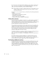
... following information available: v Machine type and model v Serial numbers of your hardware products v Description of the problem v Exact wording of any error messages v Hardware and software configuration information Using other services If you can purchase additional services, such as depot, carry-in, or on the screen. network setup and configuration; Service will be eligible for International Warranty Service, which automatically entitles you can contact the Customer Support Center. Purchasing additional services During and after...
... following information available: v Machine type and model v Serial numbers of your hardware products v Description of the problem v Exact wording of any error messages v Hardware and software configuration information Using other services If you can purchase additional services, such as depot, carry-in, or on the screen. network setup and configuration; Service will be eligible for International Warranty Service, which automatically entitles you can contact the Customer Support Center. Purchasing additional services During and after...
User Manual
Page 86
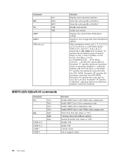
...Disable V.44 Enable V.44 Current values List of supported Select Modulation options Select modulation where: a=0, 1, 2, 3, 9, 10, 11, 12, 56, 64, 69; Parameter "b" specifies automode operations where: 0=automode disabled, 1= automode enabled with fallback options Normal data link only (same as Profile 1 Disable auto-retrain Enable auto-retrain Displays the current Select Modulation settings Displays a list of support values 66 User Guide A, b, c, d, e, f default...,V.34......, 64=Bell 103, and 69=Bell 212. Parameter "e" specifies the codec type (0= Law, and 1=A-Law). e=0-1; b=0-1;
...Disable V.44 Enable V.44 Current values List of supported Select Modulation options Select modulation where: a=0, 1, 2, 3, 9, 10, 11, 12, 56, 64, 69; Parameter "b" specifies automode operations where: 0=automode disabled, 1= automode enabled with fallback options Normal data link only (same as Profile 1 Disable auto-retrain Enable auto-retrain Displays the current Select Modulation settings Displays a list of support values 66 User Guide A, b, c, d, e, f default...,V.34......, 64=Bell 103, and 69=Bell 212. Parameter "e" specifies the codec type (0= Law, and 1=A-Law). e=0-1; b=0-1;
User Manual
Page 93
... connector 19 audio, subsystem 12 B battery location 22 BIOS, updating (flashing) 51 C cables, connecting 37 changing startup device sequence 49 changing the battery 35 CMOS, clearing 36 components locating 21 computer connecting 3 shutting down 9 turning on computer 8 connecting drives 32 connector description 19 connectors front 17 rear 18 cover removing 20 replacing 37 Customer Replacement Units (CRUs) 60 Customer Support Center 61 D device drivers 19 device, drivers 19 diagnostic CD image 9, 55, 56 diskettes 9, 55, 56, 57 PC-Doctor for DOS 54, 55 PC-Doctor for Windows...
... connector 19 audio, subsystem 12 B battery location 22 BIOS, updating (flashing) 51 C cables, connecting 37 changing startup device sequence 49 changing the battery 35 CMOS, clearing 36 components locating 21 computer connecting 3 shutting down 9 turning on computer 8 connecting drives 32 connector description 19 connectors front 17 rear 18 cover removing 20 replacing 37 Customer Replacement Units (CRUs) 60 Customer Support Center 61 D device drivers 19 device, drivers 19 diagnostic CD image 9, 55, 56 diskettes 9, 55, 56, 57 PC-Doctor for DOS 54, 55 PC-Doctor for Windows...

User Manual
Page 94
... 36 setting, changing, deleting 48 user 48 passwords considerations 47 physical specifications 14 power Advanced Configuration and Power Interface (ACPI) support 13 turning off computer 9 turning on 8 power-on self-test (POST) 51 R removing the cover 20 replacing battery 35 replacing the cover 37 Rescue and Recovery 39 S security cable lock 34 features 13, 33 integrated cable lock 35 padlock loop 35 74 User Guide selecting startup device 49 temporary startup device 49 serial connector 19 Setup Utility 47 software installing 8 specifications physical 14 system board connectors...
... 36 setting, changing, deleting 48 user 48 passwords considerations 47 physical specifications 14 power Advanced Configuration and Power Interface (ACPI) support 13 turning off computer 9 turning on 8 power-on self-test (POST) 51 R removing the cover 20 replacing battery 35 replacing the cover 37 Rescue and Recovery 39 S security cable lock 34 features 13, 33 integrated cable lock 35 padlock loop 35 74 User Guide selecting startup device 49 temporary startup device 49 serial connector 19 Setup Utility 47 software installing 8 specifications physical 14 system board connectors...

Brochure
Page 3
...)/4GB Hard disk drive5 80GB, 160GB, or 250GB or 500GB (7200rpm) Serial ATA Optical drive (full-size) CD-ROM, DVD-ROM, DVD/CD-RW Combo or DVD Recordable Audio (integrated) AD 1986 A Rear audio: line in, line out Front audio: mic in, headphone out Internal speaker Security features Client Security Solution (Software) Connectivity (integrated) Broadcom Gigabit Ethernet Expansion 2 slots (low profile) x 3 bays Dimensions 88x310x358mm (3.4x12.2x14.1") Ports 6 USB 2.0 (2 front-access), 2 serial (one optional), 1 parallel, PS/2 mouse/keyboard, VGA Keyboard Preferred...
...)/4GB Hard disk drive5 80GB, 160GB, or 250GB or 500GB (7200rpm) Serial ATA Optical drive (full-size) CD-ROM, DVD-ROM, DVD/CD-RW Combo or DVD Recordable Audio (integrated) AD 1986 A Rear audio: line in, line out Front audio: mic in, headphone out Internal speaker Security features Client Security Solution (Software) Connectivity (integrated) Broadcom Gigabit Ethernet Expansion 2 slots (low profile) x 3 bays Dimensions 88x310x358mm (3.4x12.2x14.1") Ports 6 USB 2.0 (2 front-access), 2 serial (one optional), 1 parallel, PS/2 mouse/keyboard, VGA Keyboard Preferred...


