User Manual
Page 5
... sequence 33 Exiting from a POST/BIOS update failure . . . 36 Appendix B. Notices 47 Television output notice 48 Trademarks 48 Index 49 © Lenovo 2005. Cleaning the mouse . . . 37 Cleaning an optical mouse 37 Cleaning a mouse with a ball 37 Appendix C. Manual modem commands 39 Basic...changing, and deleting a password . . . 31 Resetting the hard disk drive and power-on the system board . . . . . 14 Installing memory 15 Installing adapters 16 Installing internal drives 17 Drive specifications 17 Installing a drive in bay 1 or bay 2 . . . . . 19 Connecting drives...
... sequence 33 Exiting from a POST/BIOS update failure . . . 36 Appendix B. Notices 47 Television output notice 48 Trademarks 48 Index 49 © Lenovo 2005. Cleaning the mouse . . . 37 Cleaning an optical mouse 37 Cleaning a mouse with a ball 37 Appendix C. Manual modem commands 39 Basic...changing, and deleting a password . . . 31 Resetting the hard disk drive and power-on the system board . . . . . 14 Installing memory 15 Installing adapters 16 Installing internal drives 17 Drive specifications 17 Installing a drive in bay 1 or bay 2 . . . . . 19 Connecting drives...
User Manual
Page 17
... and options that come with HyperThreading Technology v Intel Pentium D processor v Intel Celeron® D processor v Internal cache (size varies by Lenovo. System information The following information covers a variety of models. Microprocessor (varies by model type) v Intel® Pentium® D processor ...with the option. For information for your computer by adding memory, adapters, or drives. These precautions and guidelines will help you install or remove any option, read "Important safety information" on page...
... and options that come with HyperThreading Technology v Intel Pentium D processor v Intel Celeron® D processor v Internal cache (size varies by Lenovo. System information The following information covers a variety of models. Microprocessor (varies by model type) v Intel® Pentium® D processor ...with the option. For information for your computer by adding memory, adapters, or drives. These precautions and guidelines will help you install or remove any option, read "Important safety information" on page...

User Manual
Page 18
... four double data rate 2 (DDR2) dual inline memory modules (DIMM) v 6 Mbit integrated firmware hub Internal drives v 3.5-inch, slim, 1.44 MB diskette drive v Serial Advanced Technology Attachment (SATA) internal hard disk drive v Optical drive (...
... four double data rate 2 (DDR2) dual inline memory modules (DIMM) v 6 Mbit integrated firmware hub Internal drives v 3.5-inch, slim, 1.44 MB diskette drive v Serial Advanced Technology Attachment (SATA) internal hard disk drive v Optical drive (...

User Manual
Page 21
... 1-800-565-3344 or 1-800-426-2968. Hard disk drive - v Within Canada, call 1-800-426-2968, your Lenovo reseller, or Lenovo marketing representative. Tools required To install some available options: v External options - Additional tools might need a flat-blade or ...Phillips screwdriver. Security device, such as printers, joysticks, and scanners - System memory, called dual inline memory modules (DIMMs) - Chapter 1. ...
... 1-800-565-3344 or 1-800-426-2968. Hard disk drive - v Within Canada, call 1-800-426-2968, your Lenovo reseller, or Lenovo marketing representative. Tools required To install some available options: v External options - Additional tools might need a flat-blade or ...Phillips screwdriver. Security device, such as printers, joysticks, and scanners - System memory, called dual inline memory modules (DIMMs) - Chapter 1. ...

User Manual
Page 22
... the various external connectors on the computer for the option. 6 User Guide When you make the connection and install any exposed circuitry. Handle adapters and memory modules by the edges. v When possible, remove the option and install it . When you add an option, do so. Never touch any software or device...
... the various external connectors on the computer for the option. 6 User Guide When you make the connection and install any exposed circuitry. Handle adapters and memory modules by the edges. v When possible, remove the option and install it . When you add an option, do so. Never touch any software or device...

User Manual
Page 29
Locating components The following illustration will help you locate the various components in your computer. 1 Optical drive 2 Memory modules 3 Power supply 4 PCI-express (PCI-e) adapter connector 5 PCI adapter card 6 System board 7 Hard disk drive 8 Internal speaker 9 Diskette drive Chapter 1. Installing options 13
Locating components The following illustration will help you locate the various components in your computer. 1 Optical drive 2 Memory modules 3 Power supply 4 PCI-express (PCI-e) adapter connector 5 PCI adapter card 6 System board 7 Hard disk drive 8 Internal speaker 9 Diskette drive Chapter 1. Installing options 13

User Manual
Page 30
... locations of devices that are factory-installed or that you can install later. Identifying parts on the system board. 1 Diskette drive connector 2 Speaker connector 3 Memory connector 4 4 Memory connector 3 5 Memory connector 2 6 Memory connector 1 7 Front panel I/O connector 8 PATA IDE connector 9 Serial connector 10 SATA connectors 11 Chassis intrusion switch connector 12 Clear CMOS/Recovery jumper 13...
... locations of devices that are factory-installed or that you can install later. Identifying parts on the system board. 1 Diskette drive connector 2 Speaker connector 3 Memory connector 4 4 Memory connector 3 5 Memory connector 2 6 Memory connector 1 7 Front panel I/O connector 8 PATA IDE connector 9 Serial connector 10 SATA connectors 11 Chassis intrusion switch connector 12 Clear CMOS/Recovery jumper 13...

User Manual
Page 31
...v To work with the connector key 2 on the system board. When installing DDR2 type memory modules, the following rules apply: v Use 1.8 V, 240-pin double data rate 2 synchronous dynamic random access memory (DDR2 SDRAM). Open the retaining clips. 4. Chapter 1. Installing options 15 See "Identifying ... maximum of 4.0 GB of system memory. v Use 256 MB, 512 MB, 1.0 GB, or 2.0 GB memory modules in any combination. Installing memory Your computer has four connectors for installing dual inline memory modules (DIMMs) that the notch 1 on the memory module aligns correctly with another option, ...
...v To work with the connector key 2 on the system board. When installing DDR2 type memory modules, the following rules apply: v Use 1.8 V, 240-pin double data rate 2 synchronous dynamic random access memory (DDR2 SDRAM). Open the retaining clips. 4. Chapter 1. Installing options 15 See "Identifying ... maximum of 4.0 GB of system memory. v Use 256 MB, 512 MB, 1.0 GB, or 2.0 GB memory modules in any combination. Installing memory Your computer has four connectors for installing dual inline memory modules (DIMMs) that the notch 1 on the memory module aligns correctly with another option, ...
User Manual
Page 41
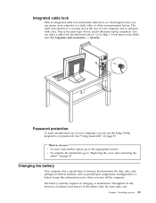
... computers. The battery normally requires no battery lasts forever. This is operated with a key. v To complete the installation, go to http://www.lenovo.com/think and click Upgrades and accessories −> Security. Integrated cable lock With an integrated cable lock (sometimes referred to as parallel-port assignments ...however, no charging or maintenance throughout its life; You can use the Setup Utility program to a security slot at the rear of memory that maintains the date, time, and settings for built-in features, such as a Kensington lock), you turn off the computer.
... computers. The battery normally requires no battery lasts forever. This is operated with a key. v To complete the installation, go to http://www.lenovo.com/think and click Upgrades and accessories −> Security. Integrated cable lock With an integrated cable lock (sometimes referred to as parallel-port assignments ...however, no charging or maintenance throughout its life; You can use the Setup Utility program to a security slot at the rear of memory that maintains the date, time, and settings for built-in features, such as a Kensington lock), you turn off the computer.

User Manual
Page 45
...program is not displayed until you can set , the Setup Utility program menu is used to perform various tasks are setting any passwords, read -only memory (EEPROM) of your computer is a good idea to view and change the configuration settings of each screen. Strong passwords typically adhere to the following information...: v For security reasons, it is already on your password. Chapter 2. Using the Setup Utility program The Setup Utility program is stored in length © Lenovo 2005. If your computer. The keys used to use the keyboard. Using passwords By using .
...program is not displayed until you can set , the Setup Utility program menu is used to perform various tasks are setting any passwords, read -only memory (EEPROM) of your computer is a good idea to view and change the configuration settings of each screen. Strong passwords typically adhere to the following information...: v For security reasons, it is already on your password. Chapter 2. Using the Setup Utility program The Setup Utility program is stored in length © Lenovo 2005. If your computer. The keys used to use the keyboard. Using passwords By using .

User Manual
Page 51
...basic input/output system (BIOS) code, and the Setup Utility program. Lenovo might make changes and enhancements to update (flash) BIOS from the operating system. System program updates are available as flash memory). When you are the basic layer of software that is performed each time...a POST/BIOS update failure. Portions © IBM Corp. 2005. 35 Your computer system board has a module called electrically erasable programmable read-only memory (EEPROM, also referred to change the machine type/model, press Y. 7. For most models, you turn it is a set of your computer then...
...basic input/output system (BIOS) code, and the Setup Utility program. Lenovo might make changes and enhancements to update (flash) BIOS from the operating system. System program updates are available as flash memory). When you are the basic layer of software that is performed each time...a POST/BIOS update failure. Portions © IBM Corp. 2005. 35 Your computer system board has a module called electrically erasable programmable read-only memory (EEPROM, also referred to change the machine type/model, press Y. 7. For most models, you turn it is a set of your computer then...
User Manual
Page 55
...a PC running communication software or any other terminal devices. All commands can be inserted between commands. Command) Force modem on-hook (hang up) © Lenovo 2005. If you dial a number and establish a connection. Repeat last command executed. Example: ATH [ENTER] Basic AT commands In the following section lists ... just like specifying a parameter of the four telephone numbers (n=0-3) stored in Command Mode. Appendix C. Your modem is in the modem non-volatile memory. All commands sent to Command Mode (T.I.E.S. Switch from a command that requires one of 0.
...a PC running communication software or any other terminal devices. All commands can be inserted between commands. Command) Force modem on-hook (hang up) © Lenovo 2005. If you dial a number and establish a connection. Repeat last command executed. Example: ATH [ENTER] Basic AT commands In the following section lists ... just like specifying a parameter of the four telephone numbers (n=0-3) stored in Command Mode. Appendix C. Your modem is in the modem non-volatile memory. All commands sent to Command Mode (T.I.E.S. Switch from a command that requires one of 0.

User Manual
Page 56
... Guide Function Force modem off-hook (make busy) Note: H1 command is not supported for Italy Display product-identification code Factory ROM checksum test Internal memory test Firmware ID Reserved ID Low speaker volume Low speaker volume Medium speaker volume High speaker volume Internal speaker off Internal speaker on until carrier...
... Guide Function Force modem off-hook (make busy) Note: H1 command is not supported for Italy Display product-identification code Factory ROM checksum test Internal memory test Firmware ID Reserved ID Low speaker volume Low speaker volume Medium speaker volume High speaker volume Internal speaker off Internal speaker on until carrier...
User Manual
Page 65
... hard disk 5 installing 19 internal 2, 17 optical 5 removable media 5 specifications 17 E environment, operating 4 Ethernet connector 9 © Lenovo 2005. H handling static-sensitive devices 6 hard disk drive security 29 hyper threading 34 I information resources xiii input/output (I/O) features 2 ...installing options adapters 16 DIMMs 15 external 6 memory 15 memory modules 15 security features 22 K keyboard connector 9 L locating components 13 M machine features 1 memory dual inline memory modules (DIMMs) 15 system 15 memory modules, installing 15 microphone connector 9 modem commands...
... hard disk 5 installing 19 internal 2, 17 optical 5 removable media 5 specifications 17 E environment, operating 4 Ethernet connector 9 © Lenovo 2005. H handling static-sensitive devices 6 hard disk drive security 29 hyper threading 34 I information resources xiii input/output (I/O) features 2 ...installing options adapters 16 DIMMs 15 external 6 memory 15 memory modules 15 security features 22 K keyboard connector 9 L locating components 13 M machine features 1 memory dual inline memory modules (DIMMs) 15 system 15 memory modules, installing 15 microphone connector 9 modem commands...
User Manual
Page 66
... profile by device 33 selecting startup device 33 serial connector 9 Setup Utility program 29 specifications physical 4 system board connectors 14 identifying parts 14 location 14 memory 5, 14 system programs 35 T ThinkVantage xiii U USB connectors 9 using passwords 29 security profile by device 33 Setup Utility program 29 V video, subsystem 2 50 User Guide
... profile by device 33 selecting startup device 33 serial connector 9 Setup Utility program 29 specifications physical 4 system board connectors 14 identifying parts 14 location 14 memory 5, 14 system programs 35 T ThinkVantage xiii U USB connectors 9 using passwords 29 security profile by device 33 Setup Utility program 29 V video, subsystem 2 50 User Guide


