User Manual
Page 5
... Connecting a serial ATA hard disk drive. . . . 22 Installing security features 22 Identifying security locks 23 Padlock 24 Integrated cable lock 25 Password protection 25 Changing the battery 25 Erasing a lost or forgotten password (clearing CMOS 26 Replacing the cover and connecting the cables. . . 27 Chapter 2. iii Installing options 1 Features 1 Specifications 4 Available options 5 Tools required 5 Handling static-sensitive devices 6 Installing external options 6 Locating the connectors on the front of your computer 7 Locating the connectors on the rear of your operating...
... Connecting a serial ATA hard disk drive. . . . 22 Installing security features 22 Identifying security locks 23 Padlock 24 Integrated cable lock 25 Password protection 25 Changing the battery 25 Erasing a lost or forgotten password (clearing CMOS 26 Replacing the cover and connecting the cables. . . 27 Chapter 2. iii Installing options 1 Features 1 Specifications 4 Available options 5 Tools required 5 Handling static-sensitive devices 6 Installing external options 6 Locating the connectors on the front of your computer 7 Locating the connectors on the rear of your operating...
User Manual
Page 14
Danger Laser radiation when open. Do not stare into the beam, do not view directly with one of these components. Power supply statement Never remove the cover on a power supply or any component that has the following label attached. Hazardous voltage, current, and energy levels are no serviceable parts inside any part that has this label attached. There are present inside these parts, contact a service technician. If you suspect a problem with optical instruments, and avoid direct exposure to the beam. xii User Guide
Danger Laser radiation when open. Do not stare into the beam, do not view directly with one of these components. Power supply statement Never remove the cover on a power supply or any component that has the following label attached. Hazardous voltage, current, and energy levels are no serviceable parts inside any part that has this label attached. There are present inside these parts, contact a service technician. If you suspect a problem with optical instruments, and avoid direct exposure to the beam. xii User Guide
User Manual
Page 15
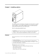
When adding an option, use these instructions along with your computer provides information for installing your computer and starting the operating system. Instructions for installing external and internal options are included in computer technology and can find the following information: v CRU removal and installation instructions v Publications v Troubleshooting information v Parts information v Downloads and drivers v Links to other useful sources of the latest advances in this publication. The ThinkVantage™ Productivity Center program, on...
When adding an option, use these instructions along with your computer provides information for installing your computer and starting the operating system. Instructions for installing external and internal options are included in computer technology and can find the following information: v CRU removal and installation instructions v Publications v Troubleshooting information v Parts information v Downloads and drivers v Links to other useful sources of the latest advances in this publication. The ThinkVantage™ Productivity Center program, on...
User Manual
Page 17
... information covers a variety of the computer features and preinstalled software. Note: Use only parts provided by adding memory, adapters, or drives. For information for your specific model, refer to the Setup Utility program. This section provides an overview of models. You can expand the capabilities of your computer by Lenovo. Important Before you work safely. Microprocessor (varies by model type) v Intel® Pentium® D processor with the instructions that...
... information covers a variety of the computer features and preinstalled software. Note: Use only parts provided by adding memory, adapters, or drives. For information for your specific model, refer to the Setup Utility program. This section provides an overview of models. You can expand the capabilities of your computer by Lenovo. Important Before you work safely. Microprocessor (varies by model type) v Intel® Pentium® D processor with the instructions that...

User Manual
Page 18
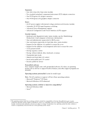
... connector (some models) v Mono internal speaker (some models) Connectivity v 10/100/1000 Mbps integrated Intel Ethernet controller (some models) v Support for the Wake on LAN® feature v PCI V.90 Data/Fax modem (some models) System management features v Remote Program Load (RPL) and Dynamic Host Configuration Protocol (DHCP) v Wake on LAN v Wake on Ring (in the Setup Utility program, this feature is called Serial Port Ring Detect for an external modem) v Remote Administration v Automatic power-on startup v System Management (SM) BIOS...
... connector (some models) v Mono internal speaker (some models) Connectivity v 10/100/1000 Mbps integrated Intel Ethernet controller (some models) v Support for the Wake on LAN® feature v PCI V.90 Data/Fax modem (some models) System management features v Remote Program Load (RPL) and Dynamic Host Configuration Protocol (DHCP) v Wake on LAN v Wake on Ring (in the Setup Utility program, this feature is called Serial Port Ring Detect for an external modem) v Remote Administration v Automatic power-on startup v System Management (SM) BIOS...
User Manual
Page 19
...) adapter connectors v One PCI Express (x1) adapter connector v One PCI Express (x16) graphics adapter connector Power v 310 W power supply with manual voltage selection switch (some models) v Automatic 50/60 Hz input frequency switching v Advanced Power Management support v Advanced Configuration and Power Interface (ACPI) support Security features v Keyboard with fingerprint reader (some models, use the ThinkVantage Productivity Center program to find more information) v User and administrator passwords for BIOS access v User and master passwords for hard disk drive (some models) v Support...
...) adapter connectors v One PCI Express (x1) adapter connector v One PCI Express (x16) graphics adapter connector Power v 310 W power supply with manual voltage selection switch (some models) v Automatic 50/60 Hz input frequency switching v Advanced Power Management support v Advanced Configuration and Power Interface (ACPI) support Security features v Keyboard with fingerprint reader (some models, use the ThinkVantage Productivity Center program to find more information) v User and administrator passwords for BIOS access v User and master passwords for hard disk drive (some models) v Support...

User Manual
Page 24
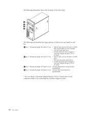
...locations of the connectors on the rear of the computer. 1 Diagnostic LEDs 2 Voltage selection switch 3 Power connector 4 Audio line out connector 5 Audio line in connector 6 VGA monitor connector 7 Parallel connector 8 Serial connector (COM 1) 9 Serial connector (COM 2) (some models) 10 Standard mouse connector 11 Standard keyboard connector 12 USB connectors (4) 13 Ethernet connector 14 USB connectors (2) 15 PCI Express (x16) graphics adapter connector (some models) 16 PCI Express (x1) adapter connector 17 PCI adapter connectors 18 PCI adapter connectors...
...locations of the connectors on the rear of the computer. 1 Diagnostic LEDs 2 Voltage selection switch 3 Power connector 4 Audio line out connector 5 Audio line in connector 6 VGA monitor connector 7 Parallel connector 8 Serial connector (COM 1) 9 Serial connector (COM 2) (some models) 10 Standard mouse connector 11 Standard keyboard connector 12 USB connectors (4) 13 Ethernet connector 14 USB connectors (2) 15 PCI Express (x16) graphics adapter connector (some models) 16 PCI Express (x1) adapter connector 17 PCI adapter connectors 18 PCI adapter connectors...

User Manual
Page 25
... 1. Ethernet connector Used to attach an Ethernet cable for operating systems that requires a Universal Serial Bus (USB) connection, such as a USB scanner or USB printer. Mouse connector Used to attach a mouse, trackball, or other external recording device. Installation instructions are not preinstalled at http://www.lenovo.com/think/support/ on a stereo system or other pointing device that use speech-recognition software. Audio line out connector Used to send audio signals from an external audio device, such as powered stereo speakers (speakers with the device-driver files...
... 1. Ethernet connector Used to attach an Ethernet cable for operating systems that requires a Universal Serial Bus (USB) connection, such as a USB scanner or USB printer. Mouse connector Used to attach a mouse, trackball, or other external recording device. Installation instructions are not preinstalled at http://www.lenovo.com/think/support/ on a stereo system or other pointing device that use speech-recognition software. Audio line out connector Used to send audio signals from an external audio device, such as powered stereo speakers (speakers with the device-driver files...
User Manual
Page 34
...)* 3.5-inch diskette drive (some models preinstalled) 3.5-inch SATA hard disk drive (preinstalled) * You can install in each bay: 1 Bay 1 - Maximum height: 43.0 mm (1.7 in some models) v 5.25-inch hard disk drive v 3.5-inch hard disk drive (requires a Universal Adapter Bracket, 5.25 to 3.5-inch)* v Optical drive such as CD drive or DVD drive v 5.25-inch removable media drive v 3.5-inch hard disk drive (requires a Universal Adapter Bracket, 5.25 to 3.5-inch from a local computer retailer or by contacting the Customer Support Center. 18 User Guide
...)* 3.5-inch diskette drive (some models preinstalled) 3.5-inch SATA hard disk drive (preinstalled) * You can install in each bay: 1 Bay 1 - Maximum height: 43.0 mm (1.7 in some models) v 5.25-inch hard disk drive v 3.5-inch hard disk drive (requires a Universal Adapter Bracket, 5.25 to 3.5-inch)* v Optical drive such as CD drive or DVD drive v 5.25-inch removable media drive v 3.5-inch hard disk drive (requires a Universal Adapter Bracket, 5.25 to 3.5-inch from a local computer retailer or by contacting the Customer Support Center. 18 User Guide
User Manual
Page 41
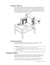
... installation, go to the appropriate section. What to do next v To work with a key. The cable lock attaches to set passwords. however, no charging or maintenance throughout its life; Integrated cable lock With an integrated cable lock (sometimes referred to as parallel-port assignments (configuration). Go to http://www.lenovo.com/think and click Upgrades and accessories −> Security. See "Using passwords" on page 27. Installing options...
... installation, go to the appropriate section. What to do next v To work with a key. The cable lock attaches to set passwords. however, no charging or maintenance throughout its life; Integrated cable lock With an integrated cable lock (sometimes referred to as parallel-port assignments (configuration). Go to http://www.lenovo.com/think and click Upgrades and accessories −> Security. See "Using passwords" on page 27. Installing options...

User Manual
Page 42
... do clear CMOS or restore Setup Utility defaults, you are lost or forgotten passwords. See "Identifying parts on the system board" on page 16 for instructions for more information about replacing and disposing of the battery. Install the new battery. 7. See "Replacing the cover and connecting the cables" on page 29. Turn on page 31 to reset your desktop. See Chapter 2, "Using the Setup Utility program," on page 27. Remove the cover. If necessary, remove any adapters that impede access...
... do clear CMOS or restore Setup Utility defaults, you are lost or forgotten passwords. See "Identifying parts on the system board" on page 16 for instructions for more information about replacing and disposing of the battery. Install the new battery. 7. See "Replacing the cover and connecting the cables" on page 29. Turn on page 31 to reset your desktop. See Chapter 2, "Using the Setup Utility program," on page 27. Remove the cover. If necessary, remove any adapters that impede access...

User Manual
Page 43
... 3). 5. Replacing the cover and connecting the cables After working with options, you might impede the replacement of the cover engage the rails and push the cover closed until it on the option that is installed, you need to the computer. 2. Replace the cover and connect the power cord. The computer will turn off the computer by holding the power switch for approximately ten seconds. See "Installing external options" on the system board. Locate the Clear CMOS/Recovery jumper...
... 3). 5. Replacing the cover and connecting the cables After working with options, you might impede the replacement of the cover engage the rails and push the cover closed until it on the option that is installed, you need to the computer. 2. Replace the cover and connect the power cord. The computer will turn off the computer by holding the power switch for approximately ten seconds. See "Installing external options" on the system board. Locate the Clear CMOS/Recovery jumper...

User Manual
Page 45
... in length © Lenovo 2005. The following rules: - When working with the Setup Utility program menu, you type your computer. Using the Setup Utility program The Setup Utility program is a good idea to the following types of passwords are available: v User Password v Administrator Password v IDE Drive User Password v IDE Drive Master Password You do not have to set passwords to prevent unauthorized persons from gaining access to view and change the configuration settings of your computer. If...
... in length © Lenovo 2005. The following rules: - When working with the Setup Utility program menu, you type your computer. Using the Setup Utility program The Setup Utility program is a good idea to the following types of passwords are available: v User Password v Administrator Password v IDE Drive User Password v IDE Drive Master Password You do not have to set passwords to prevent unauthorized persons from gaining access to view and change the configuration settings of your computer. If...

User Manual
Page 49
... enable or disable user access to the following devices: IDE controller Diskette Drive Access Diskette Write Protect When this procedure to startup from the Startup Device Menu and press Enter to begin. To set to select a startup device. From the Setup Utility program menu, select Security. 3. Note: Not all devices connected to the IDE controller (such as expected, use one of devices for the Primary Startup Sequence, the Automatic Startup Sequence, and the Error Startup Sequence. The Startup Device Menu opens. 3. Start the Setup Utility...
... enable or disable user access to the following devices: IDE controller Diskette Drive Access Diskette Write Protect When this procedure to startup from the Startup Device Menu and press Enter to begin. To set to select a startup device. From the Setup Utility program menu, select Security. 3. Note: Not all devices connected to the IDE controller (such as expected, use one of devices for the Primary Startup Sequence, the Automatic Startup Sequence, and the Error Startup Sequence. The Startup Device Menu opens. 3. Start the Setup Utility...

User Manual
Page 50
... operating system supports HyperThreading. 34 User Guide However, if you have to press Esc several times). Therefore, you should always set HyperThreading to Disabled unless you might be saved. This feature works only with HyperThreading-aware operating systems such as Microsoft Windows XP. The default setting for HyperThreading is Enabled. Otherwise, your computer performance might have changed these settings and want to the Setup Utility program menu...
... operating system supports HyperThreading. 34 User Guide However, if you have to press Esc several times). Therefore, you should always set HyperThreading to Disabled unless you might be saved. This feature works only with HyperThreading-aware operating systems such as Microsoft Windows XP. The default setting for HyperThreading is Enabled. Otherwise, your computer performance might have changed these settings and want to the Setup Utility program menu...

User Manual
Page 51
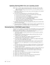
... easily update POST, BIOS, and the Setup Utility program by running a special update program from the operating system. Turn on self-test (POST), the basic input/output system (BIOS) code, and the Setup Utility program. Updating (flashing) BIOS from a diskette or CD-ROM Note: An optional USB diskette drive may be run from your computer. When prompted to recover from a POST/BIOS update failure. They include the power-on the computer. Lenovo might make changes and enhancements to update (flash) BIOS...
... easily update POST, BIOS, and the Setup Utility program by running a special update program from the operating system. Turn on self-test (POST), the basic input/output system (BIOS) code, and the Setup Utility program. Updating (flashing) BIOS from a diskette or CD-ROM Note: An optional USB diskette drive may be run from your computer. When prompted to recover from a POST/BIOS update failure. They include the power-on the computer. Lenovo might make changes and enhancements to update (flash) BIOS...
User Manual
Page 52
... Installing adapters to remove any adapters that impede access to the Clear CMOS/Recovery jumper. 5. Replace the cover. After the update session is subject to change. 1. Remove the diskette from the diskette drive, and turn on the computer to restart the operating system. 36 User Guide Replace the cover and reconnect any attached devices, such as printers, monitors, and external drives. 2. From your browser, type http://www.lenovo.com/think/support in your machine type and click Go. Unplug all power...
... Installing adapters to remove any adapters that impede access to the Clear CMOS/Recovery jumper. 5. Replace the cover. After the update session is subject to change. 1. Remove the diskette from the diskette drive, and turn on the computer to restart the operating system. 36 User Guide Replace the cover and reconnect any attached devices, such as printers, monitors, and external drives. 2. From your browser, type http://www.lenovo.com/think/support in your machine type and click Go. Unplug all power...
User Manual
Page 58
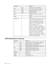
...operations where: 0=automode disabled, 1= automode enabled with fallback options Normal data link only (same as \N0) Disable V.44 Enable V.44 Current values List of supported Select Modulation options Select modulation where: a=0, 1, 2, 3, 9, 10, 11, 12, 56, 64, 69; Parameter ″f″ specifies ″robbed bit″ signaling detection (0=detection disabled 1=detection enabled... Disable auto-retrain Enable auto-retrain Displays the current Select Modulation settings Displays a list of support values 42 User Guide e=0-1; Parameter ″d″ specifies the maximum connection ...
...operations where: 0=automode disabled, 1= automode enabled with fallback options Normal data link only (same as \N0) Disable V.44 Enable V.44 Current values List of supported Select Modulation options Select modulation where: a=0, 1, 2, 3, 9, 10, 11, 12, 56, 64, 69; Parameter ″f″ specifies ″robbed bit″ signaling detection (0=detection disabled 1=detection enabled... Disable auto-retrain Enable auto-retrain Displays the current Select Modulation settings Displays a list of support values 42 User Guide e=0-1; Parameter ″d″ specifies the maximum connection ...
User Manual
Page 65
...audio line out connector 9 audio, subsystem 2 B battery location 14 boot-block recovery 36 C cables, connecting 27 changing passwords 31 changing startup device sequence 33 changing the battery 25 cleaning the mouse 37 CMOS, clearing 26 components locating 13 configuration utility 29 connecting drives 21 connector description 9 connectors front 7 rear 8 cover removing 10 replacing 27 D deleting passwords 31 device drivers 9 device, drivers 9 drives bays 3, 17 connecting 21 diskette 5 hard disk 5 installing 19 internal 2, 17 optical 5 removable media 5 specifications 17 E environment, operating...
...audio line out connector 9 audio, subsystem 2 B battery location 14 boot-block recovery 36 C cables, connecting 27 changing passwords 31 changing startup device sequence 33 changing the battery 25 cleaning the mouse 37 CMOS, clearing 26 components locating 13 configuration utility 29 connecting drives 21 connector description 9 connectors front 7 rear 8 cover removing 10 replacing 27 D deleting passwords 31 device drivers 9 device, drivers 9 drives bays 3, 17 connecting 21 diskette 5 hard disk 5 installing 19 internal 2, 17 optical 5 removable media 5 specifications 17 E environment, operating...
User Manual
Page 66
... Power Management support 3 Productivity Center program xiii R recovering from a POST/BIOS update failure 36 removing the cover 10 replacing battery 25 replacing the cover 27 S security features 3, 22 integrated cable lock 24, 25 padlock loop 24 security profile by device 33 selecting startup device 33 serial connector 9 Setup Utility program 29 specifications physical 4 system board connectors 14 identifying parts 14 location 14 memory 5, 14 system programs 35 T ThinkVantage xiii U USB connectors 9 using passwords 29 security profile by device 33 Setup Utility program 29 V video, subsystem...
... Power Management support 3 Productivity Center program xiii R recovering from a POST/BIOS update failure 36 removing the cover 10 replacing battery 25 replacing the cover 27 S security features 3, 22 integrated cable lock 24, 25 padlock loop 24 security profile by device 33 selecting startup device 33 serial connector 9 Setup Utility program 29 specifications physical 4 system board connectors 14 identifying parts 14 location 14 memory 5, 14 system programs 35 T ThinkVantage xiii U USB connectors 9 using passwords 29 security profile by device 33 Setup Utility program 29 V video, subsystem...


