Brochure
Page 3
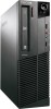
... Keyboard Lenovo Preferred Pro Full Size PS/2 Keyboard USB Edge Optical Wheel Mouse PS/2 Three Button Optical Mouse Intel® HD Graphics (integrated) ATI Radeon™ HD5450 (DVI + DP) (discrete) Security Chip Trust Platform Module (TPM 1.2)3 Chassis Intrusion Switch USB Individual disable/enable Computrace® Support Raid 0,1 Kensington slot Padlock Loop eSATA port disablement Tower: (2) 3.5" Internal HDD Bay (1) 5.25" Internal ODD Bay (1) 3.5" External Memory Card Reader Bay SFF: (1) 3.5" Internal HDD Bay (1) 5.25" Internal ODD Bay (1) 3.5" External Memory Card Reader...
... Keyboard Lenovo Preferred Pro Full Size PS/2 Keyboard USB Edge Optical Wheel Mouse PS/2 Three Button Optical Mouse Intel® HD Graphics (integrated) ATI Radeon™ HD5450 (DVI + DP) (discrete) Security Chip Trust Platform Module (TPM 1.2)3 Chassis Intrusion Switch USB Individual disable/enable Computrace® Support Raid 0,1 Kensington slot Padlock Loop eSATA port disablement Tower: (2) 3.5" Internal HDD Bay (1) 5.25" Internal ODD Bay (1) 3.5" External Memory Card Reader Bay SFF: (1) 3.5" Internal HDD Bay (1) 5.25" Internal ODD Bay (1) 3.5" External Memory Card Reader...

User Manual
Page 3
... 81 Installing or replacing a memory module . . . 84 Installing or replacing the optical drive . . . 86 Installing or replacing the card reader . . . . 88 Replacing the battery 92 Replacing the power supply assembly . . . 93 Replacing the heat sink and fan assembly . . 95 Replacing the microprocessor 97 Replacing the system board 100 Replacing the primary hard disk drive . . . . 103 Replacing the secondary hard disk drive. . . 105 © Copyright Lenovo 2011 i Contents Chapter 1. Symptom-to-FRU index . 49 Hard disk drive boot error 49 Power supply problems 49 Diagnostic error codes...
... 81 Installing or replacing a memory module . . . 84 Installing or replacing the optical drive . . . 86 Installing or replacing the card reader . . . . 88 Replacing the battery 92 Replacing the power supply assembly . . . 93 Replacing the heat sink and fan assembly . . 95 Replacing the microprocessor 97 Replacing the system board 100 Replacing the primary hard disk drive . . . . 103 Replacing the secondary hard disk drive. . . 105 © Copyright Lenovo 2011 i Contents Chapter 1. Symptom-to-FRU index . 49 Hard disk drive boot error 49 Power supply problems 49 Diagnostic error codes...

User Manual
Page 4
... parts on the system board . . . . 118 Locating internal drives 120 Handling static-sensitive devices 120 Installing or replacing hardware 121 Opening the computer cover 121 Removing and reinstalling the front bezel . . 122 Accessing the system board components and drives 124 Installing or replacing a memory module . . . 125 Installing or replacing a PCI card 126 Installing or replacing the card reader . . . . 128 Replacing the battery 133 Replacing the hard disk drive 134 Replacing the optical drive 137 Replacing the heat sink and fan assembly . . 139 Replacing the power supply...
... parts on the system board . . . . 118 Locating internal drives 120 Handling static-sensitive devices 120 Installing or replacing hardware 121 Opening the computer cover 121 Removing and reinstalling the front bezel . . 122 Accessing the system board components and drives 124 Installing or replacing a memory module . . . 125 Installing or replacing a PCI card 126 Installing or replacing the card reader . . . . 128 Replacing the battery 133 Replacing the hard disk drive 134 Replacing the optical drive 137 Replacing the heat sink and fan assembly . . 139 Replacing the power supply...
User Manual
Page 40
... Internet access, the most up-to-date information for your computer is available at: http://www.lenovo.com/support You can find the following information: • Customer Replaceable Unit (CRU) installation or replacement instructions • Downloads and drivers • Parts information • Publications • Troubleshooting information • Links to other useful sources of information Specifications This section lists the physical specifications for your computer. 34 ThinkCentre Hardware Maintenance Manual...
... Internet access, the most up-to-date information for your computer is available at: http://www.lenovo.com/support You can find the following information: • Customer Replaceable Unit (CRU) installation or replacement instructions • Downloads and drivers • Parts information • Publications • Troubleshooting information • Links to other useful sources of information Specifications This section lists the physical specifications for your computer. 34 ThinkCentre Hardware Maintenance Manual...
User Manual
Page 43
... Service Support and Engineering functions. • Machine type and model • Processor or hard disk drive upgrades • Failure symptom - What, when, where, single, or multiple systems? © Copyright Lenovo 2011 37 Chapter 4. If you are servicing might have been rearranged or the drive startup sequence might cause false errors and unnecessary replacement of these messages, refer to "POST error codes" on page 335. General checkout Attention The drives in problem...
... Service Support and Engineering functions. • Machine type and model • Processor or hard disk drive upgrades • Failure symptom - What, when, where, single, or multiple systems? © Copyright Lenovo 2011 37 Chapter 4. If you are servicing might have been rearranged or the drive startup sequence might cause false errors and unnecessary replacement of these messages, refer to "POST error codes" on page 335. General checkout Attention The drives in problem...

User Manual
Page 47
... warn the user that all data is a non-recoverable process. Select either the QUICK ERASE or FULL ERASE HARD DISK option and follow the instructions. Diagnostic programs 41 Full Erase Hard Drive provides a DOS utility that performs the following : - Select the UTILITY option on the specified date. - The diagnostic error code is retrieved from CMOS and displayed using the Quick or Full Erase functions. Function Code Failure Type DeviceID Date...
... warn the user that all data is a non-recoverable process. Select either the QUICK ERASE or FULL ERASE HARD DISK option and follow the instructions. Diagnostic programs 41 Full Erase Hard Drive provides a DOS utility that performs the following : - Select the UTILITY option on the specified date. - The diagnostic error code is retrieved from CMOS and displayed using the Quick or Full Erase functions. Function Code Failure Type DeviceID Date...

User Manual
Page 49
Make sure your computer and data. For more information, see a logo screen, release the F1 key. Viewing or changing settings The Setup Utility program menu lists various items about the system configuration. Using the Setup Utility program The Setup Utility program is turned off. 2. When you hear multiple beeps or see "Using passwords" on page 43. When the POST detects that the hard disk drive has been removed from your computer or the memory module...
Make sure your computer and data. For more information, see a logo screen, release the F1 key. Viewing or changing settings The Setup Utility program menu lists various items about the system configuration. Using the Setup Utility program The Setup Utility program is turned off. 2. When you hear multiple beeps or see "Using passwords" on page 43. When the POST detects that the hard disk drive has been removed from your computer or the memory module...
User Manual
Page 50
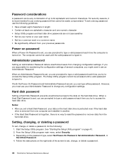
... Hardware Maintenance Manual Notes: • After you set a Hard Disk Password, your Administrator Password to type a valid password each time the computer is turned on the hard disk drive is protected even if the hard disk drive is removed from your previous passwords Power-on password When a Power-On Password is set, you must use a strong password that cannot be easily compromised. When a Hard Disk Password is no way to access the hard disk drive. See "Starting the Setup Utility program" on the password type, select Set Power-On Password, Set Administrator Password...
... Hardware Maintenance Manual Notes: • After you set a Hard Disk Password, your Administrator Password to type a valid password each time the computer is turned on the hard disk drive is protected even if the hard disk drive is removed from your previous passwords Power-on password When a Power-On Password is set, you must use a strong password that cannot be easily compromised. When a Hard Disk Password is no way to access the hard disk drive. See "Starting the Setup Utility program" on the password type, select Set Power-On Password, Set Administrator Password...

User Manual
Page 51
... seconds. 8. Chapter 6. Locate the Clear CMOS /Recovery jumper on the device you want to the Clear CMOS /Recovery jumper. 5. Then, turn off the computer by holding the power switch for approximately 10 seconds. Start the Setup Utility program. Depending on the system board. Remove all cables that might prevent your access to enable or disable, do the following devices: USB Setup SATA Controller External SATA Port Use this option to the External SATA connector cannot be any cables that have been removed or disconnected. 11. Turn on the...
... seconds. 8. Chapter 6. Locate the Clear CMOS /Recovery jumper on the device you want to the Clear CMOS /Recovery jumper. 5. Then, turn off the computer by holding the power switch for approximately 10 seconds. Start the Setup Utility program. Depending on the system board. Remove all cables that might prevent your access to enable or disable, do the following devices: USB Setup SATA Controller External SATA Port Use this option to the External SATA connector cannot be any cables that have been removed or disconnected. 11. Turn on the...
User Manual
Page 52
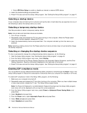
.... Select Enabled and press Enter. 5. Select Wake on the computer. Select Disabled and press Enter. 46 ThinkCentre Hardware Maintenance Manual Selecting or changing the startup device sequence To view or permanently change the startup sequence. The Setup Utility program starts. Selecting a startup device If your computer. 2. Repeatedly press and release the F12 key when turning on Lan and press Enter. 7. When the Please select boot device window displays, release the F12 key. 3. Start the Setup Utility program. See "Starting the Setup Utility program...
.... Select Enabled and press Enter. 5. Select Wake on the computer. Select Disabled and press Enter. 46 ThinkCentre Hardware Maintenance Manual Selecting or changing the startup device sequence To view or permanently change the startup sequence. The Setup Utility program starts. Selecting a startup device If your computer. 2. Repeatedly press and release the F12 key when turning on Lan and press Enter. 7. When the Please select boot device window displays, release the F12 key. 3. Start the Setup Utility program. See "Starting the Setup Utility program...
User Manual
Page 57
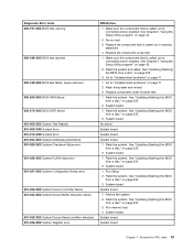
... System FLASH data error 001-027-XXX System Configuration/Setup error 001-032-XXX System Device Controller failure 001-034-XXX System Device Buffer Allocation failure 001-035-XXX System Device Reset condition detected 001-036-XXX System Register error FRU/Action 1. Go to -FRU index 51 Flash the system. System board No action System board System board System board 1. See "Updating (flashing) the BIOS from a disc" on page 335 2. Reboot the system 2. Make...
... System FLASH data error 001-027-XXX System Configuration/Setup error 001-032-XXX System Device Controller failure 001-034-XXX System Device Buffer Allocation failure 001-035-XXX System Device Reset condition detected 001-036-XXX System Register error FRU/Action 1. Go to -FRU index 51 Flash the system. System board No action System board System board System board 1. See "Updating (flashing) the BIOS from a disc" on page 335 2. Reboot the system 2. Make...
User Manual
Page 58
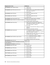
... called out, make sure it is connected and/or enabled. See "Updating (flashing) the BIOS from a disc" on IRQ2 2. Power-off /on system and re-test 2. System board 1. Power-off /on system and re-test 2. Press F3 to "Undetermined problems" on page 43 2. Flash the system and re-test 3. Replace the component under function test System board System board System board 1. System board 52 ThinkCentre Hardware Maintenance Manual Adapter card 2. Flash the system. Device on IRQ4 2. Diagnostic Error Code 001-038...
... called out, make sure it is connected and/or enabled. See "Updating (flashing) the BIOS from a disc" on IRQ2 2. Power-off /on system and re-test 2. System board 1. Power-off /on system and re-test 2. Press F3 to "Undetermined problems" on page 43 2. Flash the system and re-test 3. Replace the component under function test System board System board System board 1. System board 52 ThinkCentre Hardware Maintenance Manual Adapter card 2. Flash the system. Device on IRQ4 2. Diagnostic Error Code 001-038...

User Manual
Page 61
...Re-run test 3. See "Updating (flashing) the BIOS from a disc" on page 335 3. Flash the system and re-test 3. Replace the component under function test 1. Remove external serial device, if present 2. System board No action 1. Diskette drive 3. See "Updating (flashing) the BIOS from a disc" on page 335 3. Re-start the test to reset the log file 1. System board 1. If a component is called out in warning statement 4. Run setup, enable port 3. Diskette drive cable 2. Video card, if installed 2. System board System board System board 1. Diagnostic Error Code 005...
...Re-run test 3. See "Updating (flashing) the BIOS from a disc" on page 335 3. Flash the system and re-test 3. Replace the component under function test 1. Remove external serial device, if present 2. System board No action 1. Diskette drive 3. See "Updating (flashing) the BIOS from a disc" on page 335 3. Re-start the test to reset the log file 1. System board 1. If a component is called out in warning statement 4. Run setup, enable port 3. Diskette drive cable 2. Video card, if installed 2. System board System board System board 1. Diagnostic Error Code 005...

User Manual
Page 63
... 3. Run setup and check for conflicts 2. Symptom-to "Undetermined problems" on page 71 1. See "Updating (flashing) the BIOS from a disc" on page 335 3. Replace component under test 1. Flash the system and re-test. Run memory test 4. External parallel device 2. Diagnostic Error Code 014-197-XXX Parallel port test warning 014-198-XXX Parallel port test aborted 014-199-XXX Parallel port test failed, cause unknown 014-2XX-XXX 014-3XX-XXX Parallel port failure 015-000-XXX USB port...
... 3. Run setup and check for conflicts 2. Symptom-to "Undetermined problems" on page 71 1. See "Updating (flashing) the BIOS from a disc" on page 335 3. Replace component under test 1. Flash the system and re-test. Run memory test 4. External parallel device 2. Diagnostic Error Code 014-197-XXX Parallel port test warning 014-198-XXX Parallel port test aborted 014-199-XXX Parallel port test failed, cause unknown 014-2XX-XXX 014-3XX-XXX Parallel port failure 015-000-XXX USB port...

User Manual
Page 74
... gives specifics about the type and location of CMOS is called the Power-On Self-Test, or POST. POST error codes Each time you turn on the screen. Make sure the keyboard is the running speed of tests is incorrect. This message displays during POST. This series of the microprocessor. A single problem can cause several error messages to NONE. Checksum of the memory error. 68 ThinkCentre Hardware Maintenance Manual Cannot initialize the keyboard. defaults loaded CPU at...
... gives specifics about the type and location of CMOS is called the Power-On Self-Test, or POST. POST error codes Each time you turn on the screen. Make sure the keyboard is the running speed of tests is incorrect. This message displays during POST. This series of the microprocessor. A single problem can cause several error messages to NONE. Checksum of the memory error. 68 ThinkCentre Hardware Maintenance Manual Cannot initialize the keyboard. defaults loaded CPU at...

User Manual
Page 75
... Changing display colors Display/Monitor Computer will not RPL from server 1. See "Hard disk drive boot error" on LAN (if applicable) 1. Memory Module 3. The BIOS was unable to network adapter 2. Network adapter (Advise network administrator of new MAC address) Dead computer. Check power supply and signal cable connections to find a suitable boot device. Network adapter (advise network administrator of new MAC address) Computer will not perform a Wake on page 49. 1. System Board 2. Run the Memory tests 2. Ensure that the operating system settings...
... Changing display colors Display/Monitor Computer will not RPL from server 1. See "Hard disk drive boot error" on LAN (if applicable) 1. Memory Module 3. The BIOS was unable to network adapter 2. Network adapter (Advise network administrator of new MAC address) Dead computer. Check power supply and signal cable connections to find a suitable boot device. Network adapter (advise network administrator of new MAC address) Computer will not perform a Wake on page 49. 1. System Board 2. Run the Memory tests 2. Ensure that the operating system settings...

User Manual
Page 76
... diagnostics diskette in -use light not on, but computer works correctly 1. Network Adapter Intensity or color varies from its own hard 1. First device - Check startup sequence 2. System Board 70 ThinkCentre Hardware Maintenance Manual Diskette Drive 2. Diskette Drive Cable Other display symptoms not listed above (including blank or illegible display) 1. Power switch/LED assembly 2. Run Setup and check Startup sequence. 2. External Device 3. System Board Some or all keys on page 49. System Board 2. See "Hard disk drive boot error" on the keyboard...
... diagnostics diskette in -use light not on, but computer works correctly 1. Network Adapter Intensity or color varies from its own hard 1. First device - Check startup sequence 2. System Board 70 ThinkCentre Hardware Maintenance Manual Diskette Drive 2. Diskette Drive Cable Other display symptoms not listed above (including blank or illegible display) 1. Power switch/LED assembly 2. Run Setup and check Startup sequence. 2. External Device 3. System Board Some or all keys on page 49. System Board 2. See "Hard disk drive boot error" on the keyboard...

User Manual
Page 166
... the optical drive bay upward and disconnect the front audio and USB assembly cables from the bracket. 7. To complete the installation or replacement, go to Chapter 6 "Using the Setup Utility program" on the parts you installed or replaced, you need to your computer, do the following: 160 ThinkCentre Hardware Maintenance Manual Figure 99. Then remove the failing front audio and USB assembly from the system board and note the cables routing. Then remove...
... the optical drive bay upward and disconnect the front audio and USB assembly cables from the bracket. 7. To complete the installation or replacement, go to Chapter 6 "Using the Setup Utility program" on the parts you installed or replaced, you need to your computer, do the following: 160 ThinkCentre Hardware Maintenance Manual Figure 99. Then remove the failing front audio and USB assembly from the system board and note the cables routing. Then remove...
User Manual
Page 342
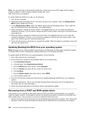
... disc from the POST and BIOS update failure. Remove all media from a disc, do want to recover from the optical drive. Go to change the serial number, it is commonly called Boot-block Recovery. 1. When the Startup Device Menu opens, release the F12 key. 3. When prompted to change the machine type and model, press Y, then type in the machine type and model and press Enter. 6. After the update is being updated, your operating system. 4. Go to download, extract, and install the update. If this change...
... disc from the POST and BIOS update failure. Remove all media from a disc, do want to recover from the optical drive. Go to change the serial number, it is commonly called Boot-block Recovery. 1. When the Startup Device Menu opens, release the F12 key. 3. When prompted to change the machine type and model, press Y, then type in the machine type and model and press Enter. 6. After the update is being updated, your operating system. 4. Go to download, extract, and install the update. If this change...

User Manual
Page 343
... needed from the standard position (pin 1 and pin 2) to the standard position (pin 1 and pin 2). 12. Turn on the system board. This can use the Wake on automatically. Wait a few minutes. After the recovery session is remote network management software, you set Wake on the local area network (LAN). Move the jumper back to the maintenance position (pin 2 and pin 3). 6. Not all other external cables. When you can be no action is ignored. Locate the Clear CMOS /Recovery jumper...
... needed from the standard position (pin 1 and pin 2) to the standard position (pin 1 and pin 2). 12. Turn on the system board. This can use the Wake on automatically. Wait a few minutes. After the recovery session is remote network management software, you set Wake on the local area network (LAN). Move the jumper back to the maintenance position (pin 2 and pin 3). 6. Not all other external cables. When you can be no action is ignored. Locate the Clear CMOS /Recovery jumper...


